1
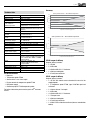
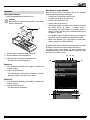
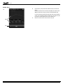
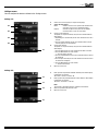
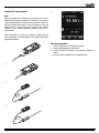
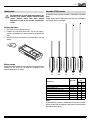
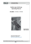
User Manual XP100 / XP101 X(pert) P(rofessional) Series · a passion for precision · passion pour la précision · pasión por la precisión · passione per la precisione · a p www.lufft.com 11_2014 Legal notice Table of contents Notes regarding the operating manual .................................... 01 Information about the device................................................... 02 Technical data ........................................................................ 03 Safety ..................................................................................... 04 Transport and storage............................................................. 04 Operation................................................................................ 05 PC software ............................................................................ 14 Errors and faults ..................................................................... 14 Maintenance ........................................................................... 15 Disposal.................................................................................. 16 Declaration of conformity ........................................................ 16 Notes regarding the operating manual Preface The operating manual only describes the temperature measuring device and its intended use. Detailed descriptions of the sensors and optional accessories as well as tips for proper and practical use of the temperature measuring device are not included in this operating manual. The current version of the operating manual and the general catalogue can be found at: www.lufft.de Symbols Hazardous electric current! Warns about hazards from electric current which can lead to injuries or even death. Danger! Warns of a hazard which can lead to personal injury. Caution! Warns of a hazard which can lead to damage to property. Definitions Concept Meaning SmartGraph3 PC software for analysis and visualisation of measured values EN This release replaces all previous versions. No part of this publication may be reproduced without written permission from Lufft®. The same applies for electronically processing, duplicating or spreading the publication. Subject to technical changes. All rights reserved. Trademarks are used without guarantee that they may be used freely and primarily following the spelling of the manufacturer. Product names are registered. Changes to construction in the interests of constant improvements to the product, as well as changes to the shape and colour are reserved. The scope of delivery may vary from product images. This document was created with all due care. Lufft® accepts no liability whatsoever for possible mistakes or omissions. The only party responsible for determining measured results to be valid, drawing conclusions and deriving actions is the user! Lufft® accepts no claims of warranty for correctness of detected measured values or measured results. Further, Lufft® accepts no liability whatsoever for possible mistakes or damage which have been caused by utilising the detected measured results. © Lufft® Warranty The warranty is for 12 months. Damages caused by incorrect use by untrained people or start-up by unauthorised people are excluded from the warranty. The device complies with the fundamental health and safety requirements of the applicable EU regulations and was tested at the factory for perfect functionality multiple times. However, if faults in the functionality occur and cannot be remedied with the measures in the chapter Errors and faults, please get in touch with your dealer or distributor. When making a warranty claim, supply the device number (see the rear of the device). The invoice acts as warranty certificate. When manufacturer's instructions or legal regulations have not been followed, or after unauthorised changes to the device are made, the manufacturer is not responsible for the resulting damages. Changes to the device or unauthorised replacement of individual parts can drastically impact the electrical safety of this product and leads to the forfeit of the warranty. Liability does not extend to damages to people or property caused by the device being used other than as described in the instructions in this operating manual. Subject to changes to technical design and model changes as part of constant development and product improvement without prior notice. No liability is accepted for damages resulting from improper use. In such cases, entitlements to a warranty are then also forfeited. Operating manual – temperature measuring device XP100 / XP101 1 11_2014 Device depiction Information about the device Description of the device The temperature measuring device XP100 / XP101 is used for carrying out accurate measured value detection. To do so, you can connect different temperature probes of type PT1000 to the device interface. The operating elements are found on the front and sides of the robust housing. A scratch-proof colour display with touch function (1) allows entering and selecting values and functions and also displaying detected results. You can also navigate the device software by using the cross control (3) and the OK button (5) and select measuring functions. By pressing the Back key (2) you return to the previous screen of the device software. Pressing the Menu key (6) directly opens the main menu. Pressing the Illumination key (4) either switches the background illumination for the colour display and the keys on or dims them. Located above the colour display (1) is the connection for the digital sensors (7). Here you can connect the sensor. The measured results of the connected sensor are shown in the device's colour display (1). The On/Off key (9) and a USB connection (10) are found on the sides of the device. 1 2 3 6 4 5 7 You can connect the device to a computer by using the supplied USB connection cable. Then you can extract and analyse your measured results with the SmartGraph3 software. 8 10 2 9 No. Operating element 1 2 3 4 5 6 7 8 9 10 Scratch-proof colour display with touch function Back key Cross control with Up, Down, Left, Right keys Illumination key OK button Menu key Connection for PT100 sensors (4-pin) Battery compartment with battery cover On/Off key Micro USB connection Operating manual – temperature measuring device XP100 / XP101 EN 11_2014 Accuracy Technical data electr. precision at 10°C ... 30°C ambient temperature 0,06 Temperature probe Measuring range Resolution Electrical accuracy at 10 °C to 30 °C ambient temperature System accuracy (XP101) PT100 according to DIN EN 60751 -200 °C to +850 °C 0.001 K 0.01 K at temperatures ≤ 0 °C at the sensor 0.01 K + 0.00005 * temperature in °C at temperatures > 0 °C at the sensor 5 mK at 0 °C; 20 mK (-40 °C...+200 °C) (individual determination of the sensor characteristic) 4-wire 1 mA DC with duty factor 50 % = 0.50 mA 1.85 measurements /s 1 mA DC with duty factor 33 % = 0.33 mA 1.25 measurements /s Measuring circuit Measuring current normal operation Measuring current root 2 function Elimination of thermoelectric voltage Operating temperature Storage temperature Battery type Power consumption (with illumination) Dimensions (length x width x height) Weight Memory Display Power input active Battery lifespan passive Battery lifespan active Resolution yes, automatically 0 °C to +50 °C (with < 90 % RH) -20 °C to +60 °C (with < 95 % RH) 4 x Alkaline LR6 AA, 1.5 V batteries approx. 40 mA 127 x 83 x 42 mm 290 g for approx. 200 measuring projects consisting of up to 3 x 3600 (=10,800) measuring points, that is a total of 200 x 10800 = 2160000 measuring points touchscreen, capacitive, TFT, resolution 240x320, 65535 colours, sunlight-readable approx. 400 mW approx. 1 year at least 24 hours to 3 decimal places Bag/case Temperature probe PT100 Sensor cable: 2 m or 10 m length Plug to connect the temperature probe PT100 USB power supply Connector plug for PT100 temperature probe For further information please contact your Lufft® customer service. EN 0,02 0 -0,02 -0,04 -0,06 -200 0 10 20 30 40 50 100 200 300 400 500 600 700 800 900 temperature of the measuring object in °C electr. precision at 50 ... 90°F ambient temperature 0,15 0,1 0,05 0 -0,05 XP100 accessories • • • • • • 0,04 precision in °C Value precision in °F Parameter -0,1 -0,15 -330 32 50 70 90 110 130 210 400 600 800 1000 1200 1400 1600 Temperature of the measured object in °F XP100 scope of delivery Scope of delivery includes: • 1 x XP100 • 1 x USB cable • 4 x Alkaline LR6 AA, 1.5 V batteries • 1 x Getting started guide • 1 x Factory test certificate XP101 scope of delivery Scope of delivery includes: • 1 x XP101 with stored sensor characteristic curve for the supplied probe • 1 x Temperature probe PT100, type 3120.700, aged and calibrated • 1 x Sensor cable of 2 m length • 1 x USB cable • 4 x Alkaline LR6 AA, 1.5 V batteries • 1 x Transport case • 1 x Getting started guide • 1 x Factory test certificate • 1 x DAkks / DKD calibration certificate (German accreditation bodies) Operating manual – temperature measuring device XP100 / XP101 3 11_2014 Residual risks Safety Danger! Do not leave the packaging lying around. Children may use it as a dangerous toy. Carefully read the operating manual before using the device and keep it within reach! • Do not use the device in atmospheres containing oil, sulphur, chlorine or salt. • Never use the device for measurements at live parts. • Ensure that all connection cables are protected from damages (e.g. from kinks or crushing). • Protect the device from permanent direct sunlight. • Observe the storage and operating conditions (see chapter Transport and storage). Danger! The device is not a toy and does not belong in the hands of children. Danger! Dangers can occur at the device when it is used by untrained people in an unprofessional or improper way. Observe the personnel qualifications. Caution! To prevent damages to the device, do not expose it to extreme temperatures, extreme humidity or moisture. Intended use Only use the thermometer XP100 / XP101 for temperature measurements in dry surroundings. In doing so, observe the technical data. To use the device for its intended use, only connect and use accessories and spare parts which have been approved by Lufft®. Improper use Do not use the device in potentially explosive areas. Lufft® accepts no liability for damages resulting from improper use. In such a case, entitlements to a warranty are forfeited. Any unauthorised modifications, alterations or structural changes to the device are forbidden. Caution! Do not use abrasive cleaners or solvents to clean the device. Transport and storage Transport Use a suitable bag to transport the device safely. The XP101 is delivered with a transport case. Personnel qualifications Storage People who use this device must: • have read and understood the operating manual, especially the Safety chapter. When the device is not being used, observe the following storage conditions: • dry, • protected from dust and direct sunlight, • with a plastic cover to protect it from invasive dust, if necessary. • The storage temperature is the same as the range given in the chapter . • When storing the device for a long time, remove the batteries. For maintenance or repair work which requires the housing to be opened, contact Lufft® customer service. Devices which have been opened unlawfully are void of any warranty and warranty claims. 4 Operating manual – temperature measuring device XP100 / XP101 EN 11_2014 Description of screen elements Operation Inserting the batteries • Insert the supplied batteries before first use. Caution! Make certain that the surface of the device is dry and the device is switched off. 8 1. Open the cover of the battery compartment (8). 2. Insert the batteries with correct polarity. 3. Close the cover of the battery compartment (8). – The device can now be switched on. When using the device, take special note of the following important operating elements and displays: • The Back key (2) opens the previous menu. • The Menu key (6) opens the main menu. • Name of the current screen (15). • Display of the current time (11). • The padlock symbol (12) appears when you press and hold the On/Off key (9) for approx. 1 second during a measurement. The touch function of the colour display is locked. To release the lock, press and hold the On/Off key (9) for approx. 1 second. • The lightbulb symbol (13) appears when you have used the Illumination key (4) to switch on background illumination. • Battery level indicator (14); a plug symbol is shown when power is supplied via a USB connection. All options which can be selected via touch function can also be selected by using the cross control and the OK button (5). For safety reasons, some options can only be selected and configured by using the cross control and the OK button (e.g. date and time in the Settings screen). 11 12 13 15 14 6 2 Switch-on 1. Press and hold the On/Off key (9) for approx. 3 seconds until a beep is emitted. 2. Let go of the On/Off key (9). – The colour display is switched on. The device is ready for operation as soon as the main menu is shown. Switch-off 1. Press and hold the On/Off key (9) for approx. 3 seconds until a beep is emitted. 2. Let go of the On/Off key (9). – The device will be switched off. EN Operating manual – temperature measuring device XP100 / XP101 5 11_2014 Set language Main menu 1. Press the Menu key (6) to open the main menu. You can open the following menus from the main menu: 6 2 2. Press the Settings button in the main menu. 3. Press the language selection button (16) in the Settings screen. 16 Measuring mode: Archive: Settings: Perform measurements with the connected sensor. Open archived measured values. Make any device settings. 4. Press the button with the desired language from the following screen. – The selected screen language is activated immediately. 5. Press the Back key (2) to return to the desired measuring mode. Alternatively press the Menu key (6) and then the Measuring mode button. 6 Operating manual – temperature measuring device XP100 / XP101 EN 11_2014 Archive screen In the Archive screen, you can view archived measuring projects or open them for further processing: Archive, fig. A.: A. 20 20 21 22 21 22 Shows the measuring projects which are saved in the archive. The currently selected archive entry is highlighted. Navigate in the archive as follows: 1. Press the Down key on the cross control until the desired archive entry is selected. 2. You may need to turn the page by pressing the Left or Right keys on the cross control. 3. Press the OK button on the cross control to confirm the selected archive entry. You can also press OK (21) on the screen. Fig. B. opens. Selects the currently selected archive entry. => Fig. B. opens. Deletes all entries from the archive. A safety prompt opens. Confirm it by pressing the OK button if you want to delete all entries. Otherwise, touch the Cancel button. The icons beside the saved measuring projects show each measuring mode (see examples in fig. A.). The meaning is as follows: Spot measurement Time measurement Archive, fig. B.: 23 24 B. 25 Opens the selected archive entry (see fig. C.). Deletes the selected archive entry. A safety prompt opens. Confirm it by pressing the OK button if you want to delete the entry. Otherwise, touch the Cancel button. Closes fig. B. and returns to fig. A. 23 24 25 EN Operating manual – temperature measuring device XP100 / XP101 7 11_2014 Archive, fig. C.: 26 C. 27 Charts (top of fig.°C.) and tabulates (bottom of fig.°C.) the measured values. Displayed in the table are the minimum value (MIN), the maximum value (MAX), the arithmetic average (∅) and the standard deviation (SD). In case the data does not fit onto one table page after a longer recording session, you can browse through the timeline ([s], on the right in fig. C.) by using the Left and Right keys on the cross control unit. Closes the selected archive entry and returns to fig. A. 26 27 8 Operating manual – temperature measuring device XP100 / XP101 EN 11_2014 Settings screen You can configure the device as follows in the Settings screen: Settings 1/3: 16 28 16 28 29 29 30 30 31 31 Selects the screen language (see chapter Set language). Selects the unit system: Metric: Activates the metric unit system for all available measured values (e.g. for use in continental Europe). Imperial: Activates the imperial unit system for all available measured values (e.g. for use in the USA). Sets the screen brightness. This option can only be selected by using the cross control below the colour display. 1. Repeatedly press the Down key on the cross control until the scale is selected. 2. Press the Left or Right keys on the cross control to reduce (left) or increase (right) the screen brightness. Sets the date and time. This option can only be selected by using the cross control below the colour display. 1. Press the Down key on the cross control until the date is selected. 2. Press the OK button on the cross control. The entire row is selected. 3. Press the Left or Right keys on the cross control to select the value to be configured. 4. Press the Up or Down keys on the cross control to increase or reduce the value to be configured. 5. Press the OK button on the cross control. The row is deselected. Opens the next screen. Settings 2/3: 32 32 33 33 34 34 35 Either specifies the period for automatic dimming of the colour display or deactivates the function: 30 seconds, 1 minute, 5 minutes, off Either specifies the period for automatic switch-off of the colour display or deactivates the function: 10 minutes, 30 minutes, 1 hour, off Note! This function is deactivated during an automatic measurement. Switches signal tones/key tones on or off. Opens the next screen. 35 EN Operating manual – temperature measuring device XP100 / XP101 9 11_2014 Settings 3/3: 36 A. 36 37 38 37 39 B. 38 Configures the duty factor at the sensor: normal duty factor 50 % sqrt(2) duty factor 33 % Changing the duty factor enables the determination of the sensor's self-heating. This measuring method can be used for high-precision measurements at fixed points, such as the water triple point, and in suitable media ensuring a high temperature stability. The selected setting is displayed on the screen if it differs from the setting Normal. Here, the linearisation function can be selected. The following options are available: IEC 60751 default setting for PT100 ITS-90 for spectrally pure platinum resistance thermometers Only available for the XP101. Contains stored characteristic XP101 curve for the supplied sensor Note! Before using the measuring device, make sure that you are aware of the device's intended purpose and the respective standard in effect as well as the contents of this standard. Here, different coefficients can be selected and entered by hand. Once you changed the coefficient, *U is displayed behind the selected linearisation function in the measuring mode. The coefficient selection options depend on the selected linearisation function. Indicated below are the editable coefficients with their default values: R0 = 100 Ω IEC 60751 ITS-90 XP101 Note! Incorrect coefficients can lead to large measurement deviations! C. 39 D. 10 A = +3.9083*10-3 °C-1 B = -5.7750*10-7 °C-2 C = -4.1830*10-12 °C-3 For explanations regarding ITS-90 see below. The coefficients for this function cannot be edited. Change the value for a coefficient as follows: 1. Click on the Coefficients button. 2. Press the button with the desired coefficient (see fig. B. for IEC 60751 or fig. C. for ITS-90). 3. Enter the desired value by use of the buttons (example fig. D.) 4. Confirm the entry by pressing OK. 5. To reset a default value, press the recycle bin icon. Note! This function is not available if XP101 was selected as linearisation function. Offset Offset value range: -10 °C to +10 °C Once you changed the offset, *U is displayed behind the selected linearisation function in the measuring mode. The offset value is added to the measured temperature value. Note! This function is not available if XP101 was selected as linearisation function. Operating manual – temperature measuring device XP100 / XP101 EN 11_2014 Explanations regarding ITS-90: Calculation of the deviation to the reference function ΔW: W corresponds to the sensor's current resistance divided by the sensor's resistance at the water triple point (0.01°C). a1) If W < 1 and cL1 = 0 (for the range from -190°C to 0.01°C): In that event the parameter cL1 is bracketed in the selection: (cL1) ΔW = aL[W - 1] + bL[W - 1] ln W Default setting: aL = 0; bL = 0; cL1 = 0 a2) If W < 1 and cL1 ≠ 0 (for the range from -219°C to 0.01°C): In that event the parameter cL1 is displayed as usual in the selection: cL1 ΔW = aL[W - 1] + bL[W - 1]2+ cL1[ln W ]2 b) If W >= 1 ΔW = aH[W - 1] + bH[W - 1]2 + cH[W - 1]3 + dH[W - W Al)]2 Default setting: aH = 0; aH = 0; cH = 0; dH = 0; W-Al = 3.3760086 Measuring mode screen A. 40 41 42 40 43 41 44 45 42 43 44 45 46 47 B. 46 47 EN Indicates the current temperature value. Displays information on the current measuring mode and the characteristic curve. This symbol indicates, that the displayed measured values under 43 are calculated (e.g. minimum/maximum measured value). Indicates the calculated measured values according to the selection (e.g. minimum/maximum measured value). Sets the measured values displayed under 43 and the duration back to zero. Specifies how the measured values under 43 are shown (see fig. B.): Minimum: Always shows the smallest detected measured value from a measuring period. Maximum: Always shows the largest detected measured value from a measuring period. Average: Shows the average value of all measured values which have been detected so far from a measuring period. Hold: Pauses the current detected measured value and shows it continually (when this option is selected). Off: Switches the display (42) off. Carries out an automatic measurement for the duration of an already specified recording interval. The recording interval can be specified in the following screen (see fig. C. and fig. D.). Saves the currently displayed measured value as single measurement in the archive with date and time stamp. Operating manual – temperature measuring device XP100 / XP101 11 11_2014 Measuring mode – Automatic measurement screen C. 48 49 50 51 Shows the measured temperature value. Shows the remaining time until the automatic measurement finishes. Opens a screen for selecting the recording duration (see fig. D.). Starts recording. The key turns red once recording has started. 48 52 49 53 50 51 52 Note! During an active recording it is not possible to switch off the measuring device with the On/Off key. Automatic switch-off is also deactivated. First stop the recording by pressing key 52 and then turn off the device. Stops the current recording. The detected values are automatically saved to the current measuring project. Pauses the current recording. Key 51 continues to be illuminated in red. Press key 53 again to resume recording. 53 D. 12 Operating manual – temperature measuring device XP100 / XP101 EN 11_2014 Carrying out a measurement E. Note: Note that moving from a cold area to a warm area can lead to condensation forming on the device's circuit board. This physical and unavoidable effect can falsify the measurement. In this case, the colour display shows either no measured values or they are incorrect. Wait a few minutes until the device has become adjusted to the changed conditions before carrying out a measurement. Upon connection of a sensor the devices changes into the measuring mode. The corresponding screen is displayed and the measurement begins. A. Shut down procedure 1. Use the On/Off key (9) to switch the device off. 2. Detach connecting cables and sensors. 3. Clean the device according to the chapter Cleaning the device. 4. Store the device according to the chapter Storage. B. C. D. EN Operating manual – temperature measuring device XP100 / XP101 13 11_2014 PC software Starting the PC software Use the SmartGraph3 PC software to carry out a detailed analysis and visualisation of your measured results. Only by employing this PC software can all options of the measuring device for visualization and functioning be utilized (e.g. data export into an Excel/PDF file or data output in form of a printout). 1. Start the SmartGraph3 software. 2. Switch the device on, if required. 3. Connect the device to your PC via the USB connection cable provided in the scope of delivery. After a few seconds (up to one minute) the device is automatically detected and added to the device list in the SmartGraph3 software. Installation conditions Ensure that the following minimum requirements for installing the SmartGraph3 PC software are fulfilled: • Supported operating systems (32 or 64 bit version): – Windows Vista – Windows 7 – Windows 8 • Software requirements: – Microsoft .NET Framework (is automatically installed during the software installation, where applicable) • Hardware requirements: – Processor speed: min. 1.6 GHz – USB connection – 2 GB RAM, minimum – 1 GB hard disk space, minimum Installing the PC software 1. Download the current PC software from the Internet. To do so, visit the website www.smartgraph3.de/download. 2. Double-click the downloaded file. 3. Follow the instructions of the installation wizard. 14 Information about using the PC software is provided in the online help. Errors and faults The accurate functionality of the device was tested during production a number of times. However, if functionality faults do occur, then check the device according to the following list. The device does not switch on: • Check the charging status of the batteries. Change the batteries when the message Batt lo is displayed upon switch-on. • Check that the batteries are properly positioned. Check the polarity is correct. • Never carry out an electrical check yourself; instead, contact your Lufft® customer service. Operating manual – temperature measuring device XP100 / XP101 EN 11_2014 Maintenance Available PT100 sensors For maintenance or repair work which requires the housing to be opened, contact Lufft® customer service. Devices which have been opened unlawfully are void of any warranty and warranty claims. An overview of the currently available PT100 sensors is provided below. Further details about PT100 sensors and their use is provided in the separate general catalogue. Cleaning the device 1. Use a soft, lint-free cloth for cleaning. 2. Dampen the cloth with clean water. Do not use sprays, solvents, alcohol-based or abrasive cleaners to dampen the cloth. 3. Remove dirt from the housing, the connections and the display. Battery change Change the batteries when the message Batt lo is displayed upon switch-on or the device can no longer be switched on. See Inserting the batteries on page 5. 3120. 530 3120. 540 PT100 sensor Article number Immersion probe, short Immersion probe, long Immersion/penetration probe, long Stainless steel food penetration probe Immersion probe for XP100 Surface probe Precision ceramic probe for XP101 3120.520 3120.530 3120.540 3120.550 3120.560 3120.600 3120.700 3120. 700 Compatible with XP101 3120. 600 XP100 3120. 520 X X X X X X X X X X X X Note! Lufft® continually improves and broadens the range of available sensors. Information on additional, new sensors can be found on the website www.lufft.de. EN Operating manual – temperature measuring device XP100 / XP101 15 11_2014 Connecting third-party sensors Disposal When connecting third-party sensors to the device, only use the original plug-in connector (article number: 3120.50). The maximally permissible connection cross-section is 0.75 mm². Please observe the following connection diagram: In the European Union, electronic equipment must not be treated as domestic waste, but must be disposed of professionally in accordance with Directive 2002/96/EC of the European Parliament and Council of 27th January 2003 concerning old electrical and electronic equipment. After the end of its use, please dispose of this device in a manner appropriate to the relevant legal requirements. In the European Union, batteries must not be treated as domestic waste, but must be disposed of professionally in accordance with Directive 2006/66/EC of the European Parliament and Council of 6th September 2006 concerning batteries and accumulators. Please dispose of batteries in a manner appropriate to the relevant legal requirements. No. Designation Pin 1 Pin 2 Pin 3 Pin 4 Force High (+) Sense High (+) Sense Low (-) Force Low (-) Declaration of conformity Note! Sensors must be connected using the 4-wire technique, the 3-wire technique is not supported. in accordance with the EC Low Voltage Directive 2006/95/EC and the EC Directive 2004/108/EC about electromagnetic compatibility. Herewith, we declare that the temperature measuring device XP100 / XP101 was developed, constructed and produced in compliance with the named EC directives. Applied harmonised standards: EN 61326-1:2013 The marking is found on the rear of the device. Manufacturer: G. Lufft Mess- und Regeltechnik GmbH Gutenbergstr. 20 D-70736 Fellbach Phone: +49 711 518 22 0 Fax: +49 711 518 22 41 Email: [email protected] Fellbach, 31/08/2014 Managing Director: Axel Schmitz-Hübsch 16 Operating manual – temperature measuring device XP100 / XP101 EN G. LUFFT Mess- und Regeltechnik GmbH Lufft Germany: Fellbach Office: Postal Address: Gutenbergstrasse 20 D-70736 Fellbach Address: P.O. Box 4252 D-70719 Fellbach Tel.: +49 (0)711 51822 - 0 Fax: +49 (0)711 51822 - 41 www.lufft.com [email protected] Berlin Office: Oderstr. 59 D-14513 Teltow Tel.: +49 (0)711 51822-831 Fax: +49 (0)711 51822-944 a passion for precision · passion pour la précision · pasión por la precisión · passione per la precisione · Lufft North America: Lufft USA, Inc. 820 E Mason St #A Santa Barbara, CA 93103 Tel.: +01 919 556 0818 Fax: +01 805 845 4275 E-Mail: [email protected] www.lufft.com Beijing Office: B501 Jiatai International Mansion No. 41 East 4th Ring Road, Chaoyang District, 100025 Beijing, CHINA Tel: +86 10 65202779 Fax: +86 10 65202789 E-Mail: [email protected] Technische Änderungen vorbehalten 10 08_2014 Lufft China: Shanghai Office: Lufft (Shanghai) Measurement & Control Technology Co., Ltd. Room 507 & 509, Building No.3, Shanghai Yinshi Science and Business Park, No. 2568 Gudai Road, Minhang District, 201199 Shanghai, CHINA Tel: +86 21 5437 0890 Fax: +86 21 5437 0910 E-Mail: [email protected] www.lufft.cn