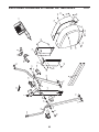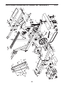
1
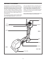
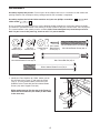
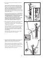
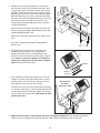
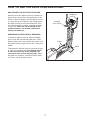
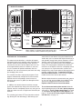
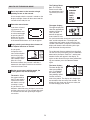
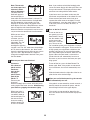
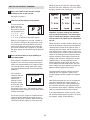
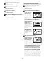
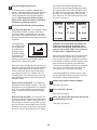
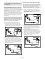
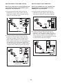
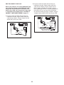
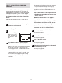
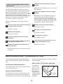
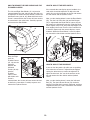
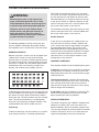
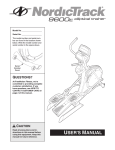
Patent Pending
Model No. NEL5095.0
Serial No.
_
USER’S MANUAL
Serial Number
Decal
QUESTIONS?
As a manufacturer, we are committed to providing complete
customer satisfaction. If you
have questions, or if parts are
damaged or missing, PLEASE
CONTACT OUR CUSTOMER
SERVICE DEPARTMENT
DIRECTLY.
CUSTOMER HOT LINE:
1-888-825-2588
Mon.–Fri., 6 a.m.–6 p.m. MST
ON THE WEB:
www.nordictrackservice.com
CAUTION
Read all precautions and instructions in this manual before using
this equipment. Keep this manual
for future reference.
Visit our website at
www.nordictrack.com
new products, prizes,
fitness tips, and much more!
TABLE OF CONTENTS
IMPORTANT PRECAUTIONS . . . . . . . . . . . . . . . . . . . . . . . . . . . . . . . . . . . . . . . . . . . . . . . . . . . . . . . . . . . . . . . .2
BEFORE YOU BEGIN . . . . . . . . . . . . . . . . . . . . . . . . . . . . . . . . . . . . . . . . . . . . . . . . . . . . . . . . . . . . . . . . . . . . . .3
ASSEMBLY . . . . . . . . . . . . . . . . . . . . . . . . . . . . . . . . . . . . . . . . . . . . . . . . . . . . . . . . . . . . . . . . . . . . . . . . . . . . . . .4
HOW TO USE THE ELLIPTICAL EXERCISER . . . . . . . . . . . . . . . . . . . . . . . . . . . . . . . . . . . . . . . . . . . . . . . . . . .7
MAINTENANCE AND TROUBLESHOOTING . . . . . . . . . . . . . . . . . . . . . . . . . . . . . . . . . . . . . . . . . . . . . . . . . . .18
CONDITIONING GUIDELINES . . . . . . . . . . . . . . . . . . . . . . . . . . . . . . . . . . . . . . . . . . . . . . . . . . . . . . . . . . . . . . .20
PART LIST . . . . . . . . . . . . . . . . . . . . . . . . . . . . . . . . . . . . . . . . . . . . . . . . . . . . . . . . . . . . . . . . . . . . . . . . . . . . . .21
EXPLODED DRAWING . . . . . . . . . . . . . . . . . . . . . . . . . . . . . . . . . . . . . . . . . . . . . . . . . . . . . . . . . . . . . . . . . . . .22
HOW TO ORDER REPLACEMENT PARTS . . . . . . . . . . . . . . . . . . . . . . . . . . . . . . . . . . . . . . . . . . . . .Back Cover
LIMITED WARRANTY . . . . . . . . . . . . . . . . . . . . . . . . . . . . . . . . . . . . . . . . . . . . . . . . . . . . . . . . . . . . . .Back Cover
IMPORTANT PRECAUTIONS
WARNING: To reduce the risk of serious injury, read the following important precautions before using the elliptical exerciser.
7. The elliptical exerciser should not be used
by persons weighing more than 250 pounds.
1. Read all instructions in this manual and all
warnings on the elliptical exerciser before
using the elliptical exerciser.
8. Wear appropriate exercise clothes when
using the elliptical exerciser. Always wear
athletic shoes for foot protection.
2. It is the responsibility of the owner to ensure
that all users of the elliptical exerciser are
adequately informed of all precautions.
9. Always hold the handgrip pulse sensor or
the handlebars when mounting, dismounting, or using the elliptical exerciser.
3. The elliptical exerciser is intended for
in-home use only. Do not use the elliptical
exerciser in a commercial, rental, or institutional setting.
10. Keep your back straight when using the elliptical exerciser; do not arch your back.
4. Keep the elliptical exerciser indoors, away
from moisture and dust. Place the elliptical
exerciser on a level surface, with a mat
beneath it to protect the floor or carpet.
Make sure that there is enough clearance
around the exercise cycle to mount, dismount, and use the elliptical exerciser.
11. If you feel pain or dizziness while exercising, stop immediately and cool down.
12. The pulse sensor is not a medical device.
Various factors may affect the accuracy of
heart rate readings. The pulse sensor is
intended only as an exercise aid in determining heart rate trends in general.
5. Inspect and properly tighten all parts regularly. Replace any worn parts immediately.
13. When you stop exercising, allow the pedals
to slowly come to a complete stop. The elliptical exerciser does not have a free wheel;
the pedals will continue to move until the
flywheel stops.
6. Keep children under age 12 and pets away
from the elliptical exerciser at all times.
WARNING:
Before beginning this or any exercise program, consult your physician.
This is especially important for persons over the age of 35 or persons with pre-existing health problems. Read all instructions before using. ICON assumes no responsibility for personal injury or
property damage sustained by or through the use of this product.
NordicTrack is a registered trademark of ICON IP, Inc.
2
BEFORE YOU BEGIN
Congratulations for selecting the new NordicTrack®
CX 938 elliptical exerciser. The CX 938 is an incredibly smooth exerciser that moves your feet in a natural
elliptical path, minimizing the impact on your knees
and ankles. And the unique CX 938 offers an impressive array of features to help you achieve your fitness
goals in the convenience of your home. Welcome to a
whole new world of natural, elliptical-motion exercise
from NordicTrack.
tions after reading this manual, see the front cover of
this manual. To help us assist you, please note the
product model number and serial number before calling. The model number is NEL5095.0. The serial
number can be found on a decal attached to the elliptical exerciser (see the front cover of this manual for
the location of the decal).
Before reading further, please familiarize yourself with
the parts that are labeled in the drawing below.
For your benefit, read this manual carefully before
you use the elliptical exerciser. If you have ques-
Fan
Console
Handlebar
Handgrip Pulse Sensor
Upright
FRONT
Wheel
Pedal
Pedal Leg
BACK
Leveling Foot
3
RIGHT SIDE
ASSEMBLY
Assembly requires two persons. Place all parts of the elliptical exerciser in a cleared area and remove the
packing materials. Do not dispose of the packing materials until assembly is completed.
Assembly requires the included allen wrenches and your own phillips screwdriver
rubber mallet
.
and
As you assemble the elliptical exerciser, use the drawings below to identify the small parts used in assembly.
The number in parentheses below each drawing is the key number of the part, from the PART LIST on page 21.
The second number is the quantity used in assembly. Note: Some small parts may have been pre-assembled. If a part is not in the parts bag, check to see if it is pre-assembled.
M10 Split
Washer (73)–2
M8 Split
Washer (85)–4
M4 x 16mm
Round Head
Screw (69)–4
7.6mm Spacer
(47)–2
M8 x 44mm Button Screw (84)–8
M8 x 56mm Button Screw (83)–4
M8 x 79mm Bolt Set (65)–2
M10 x 108mm Button Screw (70)–2
1. Identify the Front Stabilizer (8). While another person
lifts the front of the Frame (1) and holds the Pedal
Legs (4, 5) in the position shown, attach the Front
Stabilizer to the Frame with four M8 x 44mm Button
Screws (84) and a Support Plate (64).
1
1
While another person lifts the rear of the Frame (1),
attach the Rear Stabilizer (not shown) to the Frame
in the same way.
8
64
84
4
4, 5
84
2. Have another person hold the Upright (2) in the position shown.
Connect the Upper Wire Harness (30) to the Lower
Wire Harness (42). Insert the connectors on the Wire
Harnesses up into the Upright (2). Carefully pull the
upper end of the Upper Wire Harness to remove
the slack from the Wire Harnesses. See the inset
drawing. Attach the Lower Wire Harness to the Upright
with the Nylon Zip Tie (97). Pull the Nylon Zip Tie tight
and cut off the excess.
Insert the Upright (2) into the Frame (1). Be careful to
avoid pinching the Wire Harnesses (30, 42). Attach
the Upright with two M10 x 108mm Button Screws (70),
two M10 Split Washers (73), and two 7.6mm Spacers
(47). Make sure that the curved sides of the
Spacers are facing the Upright. Be careful to avoid
damaging the Wire Harnesses with the Button
Screws. Do not tighten the Button Screws yet.
3. Slide a Weld Spacer (28) onto the axle on the left side
of the Upright (2), with the open side of the Weld
Spacer facing the Upright. Apply a small amount of the
included grease to the axle.
2
Pull
30
42
73 47
70
73
1
47
97
1
42
3
Slide an Upper Body Arm (29) onto the axle on the left
side of the Upright (2). Using the included Push Nut
Tool (96), tap a Push Nut (31) onto the axle; make
sure that the Push Nut is turned as shown in the
inset drawing.
Grease
29
Attach the other Upper Body Arm (29) to the right
side of the Upright (2) in the same way.
96
31
4. Look inside one of the Handlebar Cover Sets (26) and
locate the square tabs connecting the two halves.
Gently lift the tabs and disconnect the halves.
2
2
28
31
2
29
Axle
Axle
4
Hold the two halves of the Handlebar Cover Set (26)
around the tube on the left side of the Upright (2). Align
the halves and press them together until they lock.
Attach the other Handlebar Cover Set (26) to the right
side of the Upright (2) in the same way.
2
26
5
26
5. Identify the Left Pedal (10), which has a notch near
the right side. Place the Left Pedal on the Left Pedal
Leg (4). Next, apply a generous amount of the included Teflon® lubricant to the long side of an M8 x 79mm
Bolt Set (65) and the faces of the two indicated Upper
Body Arm Bushings (12). Have a second person hold
the lower end of the left Upper Body Arm (29) inside of
the bracket on the Left Pedal Leg. Attach the Left
Pedal and the left Upper Body Arm to the Left Pedal
Leg with the Bolt Set.
5
65
29
10
Lube
65
Face
Lube
Attach the other end of the Left Pedal (10) to the Left
Pedal Leg (4) with two M8 x 56mm Button Screws (83)
and two M8 Split Washers (85).
12
4
Repeat this step on the right side of the elliptical exerciser.
85
See step 2. Tighten the two M10 x 108mm Button
Screws (70).
6. The Console (17) requires four “D” batteries (not
included); alkaline batteries are recommended.
Remove the battery cover from the bottom of the
Console. Insert four batteries into the battery compartment; make sure that the batteries are oriented as
shown by the diagram inside the battery compartment. Reattach the battery cover.
7. Have another person hold the Console (17) near the
Upright (2). Connect the Upper Wire Harness (30) to
the wire harness on the Console. Connect the Pulse
Wire (20) to the pulse wire on the Console.
Carefully insert all excess wiring down into the Upright
(2). Attach the Console (17) to the Upright with four M4
x 16mm Round Head Screws (69). (Note: The Screws
may be found in the console box.) Be careful to avoid
pinching the wires.
Notch
83
6
17
Batteries
7
Battery
Cover
Do not pinch
the wires
during this step.
69
2
17
20
30
69
8. Make sure that all parts of the elliptical exerciser are properly tightened. Cover the floor beneath the
elliptical exerciser to protect the floor from damage. Note: Some extra hardware may be left over.
6
HOW TO USE THE ELLIPTICAL EXERCISER
HOW TO MOVE THE ELLIPTICAL EXERCISER
Handlebars
Stand in front of the elliptical exerciser, hold the handlebars firmly, and place one foot against one of the
wheels. Pull the handlebars until the elliptical exerciser can be moved on the wheels, and carefully move
the elliptical exerciser to the desired location. Then,
place one foot against a wheel, and lower the elliptical exerciser. Due to the size and weight of the
elliptical exerciser, use extreme caution while
moving and lowering it.
Handgrip
Pulse Sensor
EXERCISING ON THE ELLIPTICAL EXERCISER
To mount the elliptical exerciser, hold the handgrip
pulse sensor and step onto the pedal that is in the
lowest position. Next, step onto the other pedal. Push
the pedals until they begin to move with a continuous
motion.
Pedals
Wheel
To dismount the elliptical exerciser, wait until the pedals come to a complete stop. The elliptical exerciser does not have a free wheel; the pedals will
continue to move until the flywheel stops. When
the pedals are stationary, step off the highest pedal
first. Then, step off the lowest pedal.
7
CONSOLE DIAGRAM
Note: If there is a sheet of clear plastic on the face
of the console, remove it before using the console.
FEATURES OF THE CONSOLE
sonal trainer in your home. Using the included stereo
audio cable, you can connect the elliptical exerciser to
your portable stereo, home stereo, computer, or VCR
and play special iFIT.com CD and video programs
(iFIT.com CDs and videocassettes are available separately). iFIT.com programs automatically control the
resistance of the elliptical exerciser and prompt you to
vary your pace as a personal trainer coaches you
through every step of your workout. High-energy music
provides added motivation. To purchase iFIT.com
CDs and videocassettes, call the toll-free telephone
number on the front cover of this manual.
The advanced console offers a selection of features
designed to make your workouts more enjoyable and
effective. When the manual mode of the console is
selected, the resistance of the elliptical exerciser can
be changed with the touch of a button. As you exercise, the console will provide continuous exercise
feedback. You can even measure your heart rate using
the handgrip pulse sensor.
The console also offers eight preset programs. Each
program automatically changes the resistance of the
elliptical exerciser and prompts you to increase or
decrease your pace as it guides you through an effective workout.
With the elliptical exerciser connected to your computer, you can also go to our Web site at www.iFIT.com
and access programs directly from the internet.
Explore www.iFIT.com for more information.
In addition, the console features two heart rate programs that automatically change the resistance of the
elliptical exerciser and prompt you to vary your pace to
keep your heart rate near a target heart rate while you
exercise.
To use the manual mode of the console, follow the
steps beginning on page 9. To use a preset program,
see page 11. To use a heart rate program, see page
12. To use an iFIT.com CD or video program, see
page 17. To use an iFIT.com program directly from
our Web site, see page 18.
The console also features iFIT.com interactive technology. Having iFIT.com technology is like having a per-
8
The Training Zones
bar—The Training
Zones bar will show
the approximate intensity level of your exercise.
HOW TO USE THE MANUAL MODE
1
Press any button on the console or begin
pedaling to turn on the console.
2
Select the manual mode.
3
4
A few seconds after the console is turned on, the
displays will light. A tone will then sound and the
console will be ready for use.
The upper display—
The upper display will
show the approximate
number of grams of
carbs you have
burned, the approximate number of calories you have burned, the distance you have pedaled, and the elapsed time. The display will
change from one number to the next every few
seconds. Note: When a program is selected, the
display will show the time remaining in the program instead of the elapsed time.
If you have selected
a program or the
iFIT.com mode, reselect the manual mode
by pressing the iFIT
button once or twice
until a track appears
in the matrix but the letters “iFIT” do not appear.
Begin pedaling and change the resistance of
the elliptical exerciser as desired.
As you pedal,
change the resistance of the elliptical
exerciser by pressing the 1 Step Resistance buttons. Note:
After the 1 Step
Resistance buttons are pressed, it will take a
moment for the elliptical exerciser to reach the
selected resistance level.
To see the total distance pedaled since the elliptical exerciser was purchased, press the Odometer
button twice; the words “Total Dist.” and the total
number of miles will appear in the display. To
again see the distance that you have pedaled during your workout, press the Odometer button
again.
The lower display—
The lower display will
show your pedaling
pace, in revolutions
per minute (RPM),
your pedaling speed,
and the resistance
level of the pedals. The display will change from
one number to the next every few seconds. The
display will also show your heart rate when you
use the handgrip pulse sensor.
Monitor your progress with the matrix, the
Training Zones bar, and the displays.
The matrix—When
the manual mode or
the iFIT.com mode is
selected, the matrix
will show a track representing 1/4 mile.
As you exercise, the
indicators around the track will light in succession
until the entire track is lit. The track will then darken and the indicators will again begin to light in
succession.
9
Note: The console
can show speed and
distance in either
miles or kilometers.
The letters MPH or
Km/H will appear in
the lower display to
show which unit of measurement is selected. To
change the unit of measurement, first hold down
the Start button for a few seconds. An E (for
English) or an M (for metric) will appear in the
lower display. Press the 1 Step Resistance 10 button to change the unit of measurement. Note:
When the batteries are replaced, it may be necessary to reselect the desired unit of measurement.
5
Note: If you continue to hold the handgrip pulse
sensor, the lower display will show your heart rate
for up to 30 seconds. The display will then show
your heart rate along with the other modes.
6
While you are selecting a unit of measurement, you can
also select a backlight mode. The “On”
mode keeps the
backlight on while the
console is on. The “Off” mode turns the backlight
off. To conserve the batteries, the “Auto” mode
keeps the backlight on only while you are exercising. Press the 1 Step Resistance 1 button to
change the backlight mode if desired. Then, press
the Start button.
Measure your heart rate if desired.
If your heart rate is not shown, make sure that
your hands are positioned as described. Be careful not to move your hands excessively or to
squeeze the metal contacts too tightly. For optimal performance, clean the metal contacts using
a soft cloth; never use alcohol, abrasives, or
chemicals.
Turn on the fan if desired.
To turn on the fan at
low speed, press the
Auto Breeze Fan button; the number 1 will
appear next to the
word “Fan” in the display. To turn on the
fan at medium speed, press the button a second
time; the number 2 will appear. To turn on the fan
at high speed, press the button a third time; the
number 3 will appear. To select the Auto mode,
press the button again; the words “Auto Fan” will
appear. When the auto mode is selected, the
speed of the fan will automatically increase or
decrease as you increase or decrease your pedaling speed.
To turn off the fan, press the Auto Breeze Fan
button again. Note: If the pedals are not turned
for a few minutes, the fan will automatically turn
off.
If there are
thin sheets of
plastic on the
metal contacts on the
handgrip
pulse sensor,
peel off the
Contacts
plastic. To
measure your
heart rate,
hold the handgrip pulse sensor, with your palms
resting against the metal contacts. Avoid moving
your hands or gripping the contacts tightly.
7
Slide the thumb tab on the right side of the fan to
pivot the fan to the desired angle.
When you are finished exercising, the console
will automatically turn off.
If the pedals are not moved for several seconds, a
tone will sound, the console will pause, and the
time will begin to flash in the upper display.
If the pedals are not moved for about five minutes, the console will turn off and the displays will
be reset.
When your pulse is
detected, your heart
rate will be shown in
the lower display. For
the most accurate
heart rate reading,
hold the contacts for
at least 15 seconds.
10
When the one of the “Too Fast” indicators lights,
decrease your pace. When the “On Pace” indicator lights, maintain your current pace.
HOW TO USE A PRESET PROGRAM
1
Press any button on the console or begin
pedaling to turn on the console.
2
Select one of the eight preset programs.
3
See step 1 on page 9.
To select one of the
eight preset programs, press the
Resistance/Pace button repeatedly until
“P 1,” “P 2,” “P 3,”
“P 4,” “P 5,” “P 6,”
“P 7,” or “P 8” appears in the upper display.
Important: The pace settings are intended
only to provide motivation. Your actual pace
may be slower than the pace settings. Make
sure to exercise at a pace that is comfortable
for you.
When a preset program is selected, a profile of
the resistance settings of the program will scroll
across the matrix and the maximum resistance
setting of the program will flash in the lower display. A few seconds after a program is selected,
the upper display will show how long the program
will last.
When only three seconds remain in the first segment of the program, both the Current Segment
column and the column to the right will flash, a
series of tones will sound, and all resistance settings will move one column to the left. The resistance setting for the second segment will then be
shown in the flashing Current Segment column,
and the resistance of the elliptical exerciser will
change to the resistance setting for the second
segment. Note: If all of the indicators in the
Current Segment column are lit after the resistance settings have moved to the left, the resistance settings may move downward so only the
highest indicators appear in the matrix.
Press the Start button or begin pedaling to
start the program.
Each program is divided into several one-minute
segments. One resistance setting and one pace
setting are programmed for each segment. Note:
The same resistance setting and/or pace setting
may be programmed for two or more consecutive
segments.
The program will continue until the resistance
setting for the last segment is shown in the
Current Segment column and the last segment
ends.
The resistance
setting for the first
Current Segment
segment will be
shown in the
flashing Current
Segment column
of the matrix. (The
pace settings are
not shown in the matrix.) The resistance settings
for the next several segments will be shown in the
columns to the right.
Note: During the program, you can override the
resistance setting for the current segment, if
desired, by pressing the 1 Step Resistance buttons. However, when the next segment begins,
the resistance will change if a different resistance
setting is programmed for the next segment.
If you stop pedaling for several seconds, a tone
will sound and the program will pause. To restart
the program, simply resume pedaling.
As you exercise, the Target Pace guide will help
you to keep your pedaling pace near the pace
setting for the current segment. When one of the
“Too Slow” indicators lights, increase your pace.
11
4
5
6
7
Monitor your progress with the displays.
HOW TO USE A HEART RATE PROGRAM
See step 4 on page 9.
Measure your heart rate if desired.
See step 5 on page 10.
Turn on the fan if desired.
See step 6 on page 10.
1
Press any button on the console or begin
pedaling to turn on the console.
2
Select one of the two heart rate programs.
When you are finished exercising, the console
will automatically turn off.
See step 7 on page 10.
See step 1 on page 9.
To select a heart rate
program, press the
Heart Rate Control
button once or twice
until “P 9” or “P10”
appears in the upper
display. A few seconds after a program is selected, the upper display will show how long the program will last.
If the first heart rate
program (P 9) is
selected, a profile of
the target heart rate
settings of the program will scroll across
the matrix.
3
If the second heart
rate program (P10)
is selected, a pulse
symbol will appear in
the matrix.
Enter a target heart rate setting.
If the first heart rate
program is selected,
the maximum target
heart rate setting of
the program will flash
in the lower display. If
desired, press the
increase and decrease buttons to change the
maximum target heart rate setting (see EXERCISE INTENSITY on page 20). Note: If the maximum target heart rate setting is changed, the
intensity level of the entire program will change.
If the second heart rate program is selected,
the target heart rate setting for the program will
flash in the lower display. If desired, press the
increase and decrease buttons to change the target heart rate setting (see EXERCISE INTENSITY on page 20). Note: The same target heart
rate setting will be programmed for all segments.
12
4
5
Hold the handgrip pulse sensor.
The Target Pace guide will prompt you to
increase or decrease your pedaling pace during
the program. When one of the “Too Slow” indicators lights, increase your pace. When the one of
the “Too Fast” indicators lights, decrease your
pace. When the “On Pace” indicator lights, maintain your current pace.
It is not necessary to hold the handgrip pulse
sensor continuously during a heart rate program;
however, you should hold the handgrip pulse
sensor frequently for the program to operate
properly. Each time you hold the handgrip
pulse sensor, keep your hands on the metal
contacts for at least 30 seconds.
Press the Start button to start the program.
First heart rate program—This program is divided into 20 one-minute segments. One target
heart rate setting is programmed for each segment. Note: The same target heart rate setting
may be programmed for two or more consecutive
segments.
Important: The target heart rate settings are
intended only to provide motivation. Your
actual heart rate may be slower than the target heart rate settings. Make sure to exercise
at a pace that is comfortable for you.
The target heart
Current Segment
rate setting for the
first segment will
be shown in the
flashing Current
Segment column
of the matrix. The
target heart rate
settings for the next several segments will be
shown in the columns to the right.
Note: During the program, you can manually override the resistance setting for the current segment, if desired, with the 1 Step Resistance buttons. However, when the console compares your
heart rate to the target heart rate setting, the
resistance of the elliptical exerciser may automatically increase or decrease to bring your heart
rate closer to the target heart rate setting.
When only three seconds remain in the first segment of the program, both the Current Segment
column and the column to the right will flash, a
series of tones will sound, and all target heart
rate settings will move one column to the left.
The target heart rate setting for the second segment will then be shown in the flashing Current
Segment column.
6
Second heart rate program—This program is
divided into 40 one-minute segments. The same
target heart rate is programmed for all segments.
Note: For a shorter workout, stop exercising or
select a different program before the program
ends.
7
8
Both heart rate programs—As you pedal, the
console will regularly compare your heart rate to
the target heart rate setting. If your heart rate is
too far below or above the target heart rate setting, the resistance of the elliptical exerciser will
automatically increase or decrease to bring your
heart rate closer to the target heart rate setting.
13
If you stop pedaling for several seconds, a tone
will sound and the program will pause. To restart
the program, simply resume pedaling.
Monitor your progress with the displays.
See step 4 on page 9.
Turn on the fan if desired.
See step 6 on page 10.
When you are finished exercising, the console
will automatically turn off.
See step 7 on page 10.
HOW TO CONNECT YOUR PORTABLE STEREO
HOW TO CONNECT YOUR CD PLAYER, VCR,
OR COMPUTER
Note: If your stereo has an RCA-type AUDIO OUT
jack, see instruction A below. If your stereo has a
1/8” LINE OUT jack, see instruction B. If your
stereo has only a PHONES jack, see instruction C.
To use iFIT.com CDs, the elliptical exerciser must be
connected to your portable CD player, portable stereo,
home stereo, or computer with CD player. See pages
14 and 15 for connecting instructions. To use iFIT.com
videocassettes, the elliptical exerciser must be connected to your VCR. See page 16 for connecting
instructions. To use iFIT.com programs directly from
our Web site, the elliptical exerciser must be connected to your home computer. See page 15 for connecting instructions.
A. Plug one end of the audio cable into the jack
beneath the console. Plug the other end of the cable
into the adapter. Plug the adapter into an AUDIO
OUT jack on your stereo.
A, B
HOW TO CONNECT YOUR PORTABLE CD PLAYER
AUDIO OUT
RIGHT
LEFT
Note: If your CD player has separate LINE OUT and
PHONES jacks, see instruction A below. If your CD
player has only one jack, see instruction B.
A. Plug one end of the audio cable into the jack
beneath the console. Plug the other end of the
cable into the LINE OUT jack on your CD player.
Plug your headphones into the PHONES jack.
A
PHONES LINE OUT
LINE OUT
PHONES
Headphones
Audio
Cable
Audio Cable
B. Plug one end of the audio cable into the jack
beneath the console. Plug the other end of the
cable into the LINE OUT jack on your stereo. Do
not use the adapter.
C. Plug one end of the audio cable into the jack
beneath the console. Plug the other end of the
cable into a 1/8” Y-adapter (available at electronics
stores). Plug the Y-adapter into the PHONES jack
on your stereo. Plug your headphones into the
other side of the Y-adapter.
C
B. Plug one end of the audio cable into the jack
beneath the console. Plug the other end of the
cable into a 1/8” Y-adapter (available at electronics
stores). Plug the Y-adapter into the PHONES jack
on your CD player. Plug your headphones into the
other side of the Y-adapter.
B
PHONES
Audio
Cable
1/8”
Y-adapter
Headphones
PHONES
PHONES
Audio
Cable
Adapter
1/8”
Y-adapter
Headphones
14
HOW TO CONNECT YOUR HOME STEREO
HOW TO CONNECT YOUR COMPUTER
A. Plug one end of the audio cable into the jack
beneath the console. Plug the other end of the
cable into the adapter. Plug the adapter into the
LINE OUT jack on your stereo.
A. Plug one end of the audio cable into the jack
beneath the console. Plug the other end of the
cable into the LINE OUT jack on your computer.
Note: If your stereo has an unused LINE OUT jack,
see instruction A below. If the LINE OUT jack is
being used, see instruction B.
A
Note: If your computer has a 1/8” LINE OUT jack,
see instruction A. If your computer has only a
PHONES jack, see instruction B.
A
CD
LINE OUT
VCR
Amp
Audio
Cable
LINE OUT
LINE OUT
Audio
Cable
Adapter
B. Plug one end of the audio cable into the jack
beneath the console. Plug the other end of the
cable into a 1/8” Y-adapter (available at electronics
stores). Plug the Y-adapter into the PHONES jack
on your computer. Plug your headphones or speakers into the other side of the Y-adapter.
B. Plug one end of the audio cable into the jack
beneath the console. Plug the other end of the
cable into the adapter. Plug the adapter into an
RCA Y-adapter (available at electronics stores).
Next, remove the wire that is currently plugged into
the LINE OUT jack on your stereo and plug the
wire into the unused side of the Y-adapter. Plug the
Y-adapter into the LINE OUT jack on your stereo.
B
B
PHONES
CD
Audio
Cable
VCR
Amp
Audio
Cable
1/8”
Y-adapter
Headphones/Speakers
LINE OUT
RCA
Y-adapter
Adapter
Wire removed from
LINE OUT jack
15
HOW TO CONNECT YOUR VCR
B. Plug one end of the audio cable into the jack
beneath the console. Plug the other end of the
cable into the adapter. Plug the adapter into an
RCA Y-adapter (available at electronics stores).
Next, remove the wire that is currently plugged into
the AUDIO OUT jack on your VCR and plug the
wire into the unused side of the Y-adapter. Plug the
Y-adapter into the AUDIO OUT jack on your VCR.
Note: If your VCR has an unused AUDIO OUT jack,
see instruction A below. If the AUDIO OUT jack is
being used, see instruction B. If you have a TV
with a built-in VCR, see instruction B. If your VCR
is connected to your home stereo, see HOW TO
CONNECT YOUR HOME STEREO on page 15.
A. Plug one end of the audio cable into the jack
beneath the console. Plug the other end of the
cable into the adapter. Plug the adapter into the
AUDIO OUT jack on your VCR.
A
VIDEO AUDIO
IN
OUT
B
OUT
Audio Cable
RF OUT
AUDIO OUT
RIGHT
Adapter
ANT. IN
CH
3 4
RF OUT
RCA Y-adapter
ANT. IN
CH
3 4
VIDEO AUDIO
IN
LEFT
Adapter
Wire removed from
AUDIO OUT jack
Audio Cable
16
HOW TO USE AN IFIT.COM CD OR VIDEO
PROGRAM
The program will function in almost the same way
as a preset program (see step 3 on page 11).
However, an electronic “chirping” sound will alert
you when the resistance setting and/or pace setting is about to change.
To use an iFIT.com CD or video program, the elliptical
exerciser must be connected to your CD player or
VCR. See HOW TO CONNECT YOUR CD PLAYER,
VCR, OR COMPUTER on pages 14 to 16. To purchase iFIT.com CDs or videocassettes, call the tollfree telephone number on the front cover of this
manual.
Note: If the resistance of the elliptical exerciser
and/or the pace setting does not change when
a “chirp” is heard:
• Make sure that the letters “iFIT” appear in
the display.
Follow the steps below to use an iFIT.com CD or
video program.
1
Press any button on the console or begin pedaling to turn on the console.
2
Select the iFIT.com mode.
3
• Adjust the volume of your CD player or VCR.
If the volume is too high or too low, the console may not detect the program signals.
See step 1 on page 9.
4
To select the iFIT.com
mode, press the iFIT
button. The track and
the letters “iFIT” will
light.
5
6
Press the Play button on your CD player or
VCR.
7
Note: If you are using an iFIT.com CD, insert the
CD into your CD player; if you are using an
iFIT.com videocassette, insert the videocassette
into your VCR.
A moment after the play button is pressed, your
personal trainer will begin guiding you through
your workout. Simply follow your personal trainer’s
instructions.
17
• Make sure that the audio cable is properly
connected and that it is fully plugged in.
Monitor your progress with the displays.
See step 4 on page 9.
Measure your heart rate as desired.
See step 5 on page 10.
Turn on the fan if desired.
See step 6 on page 10.
When you are finished exercising, the console
will automatically turn off.
See step 7 on page 10.
HOW TO USE PROGRAMS DIRECTLY FROM
OUR WEB SITE
Our Web site at www.iFIT.com allows you to play
iFIT.com programs directly from the internet. To use
programs from our Web site, the elliptical exerciser
must be connected to your home computer. See HOW
TO CONNECT YOUR COMPUTER on page 15. In
addition, you must have an internet connection and an
internet service provider. A list of specific system
requirements is found on our Web site.
Follow the steps below to use a program from our
Web site.
1
Press any button on the console or begin pedaling to turn on the console.
2
Select the iFIT.com mode.
5
Follow the desired links on our Web site to
select a program.
4
7
Return to the elliptical exerciser and begin
pedaling.
9
See step 2 on page 17.
Go to your computer and start an internet
connection.
Follow the on-line instructions to start the
program.
8
See step 1 on page 9.
3
6
10
11
Start your Web browser, if necessary, and go
to our Web site at www.iFIT.com.
When you start the program, an on-screen countdown will begin.
When the on-screen countdown ends, the program will begin. The program will function in
almost the same way as a preset program (see
step 3 on page 11). However, an electronic “chirping” sound will alert you when the resistance setting and/or pace setting is about to change.
Monitor your progress with the displays.
See step 4 on page 9.
Measure your heart rate if desired.
See step 5 on page 10.
Turn on the fan if desired.
See step 6 on page 10.
When you are finished exercising, the console will automatically turn off.
See step 7 on page 10.
Read and follow the on-line instructions for using
a program.
MAINTENANCE AND TROUBLESHOOTING
Inspect and properly tighten all parts of the elliptical
exerciser regularly. Replace any worn parts immediately.
batteries. See assembly step 6 on page 6 for replacement instructions.
HOW TO LEVEL THE ELLIPTICAL EXERCISER
PULSE SENSOR TROUBLESHOOTING
If the elliptical
exerciser rocks
during use, turn
one or both of
the leveling feet
under the rear
stabilizer until the
rocking motion is
eliminated.
If the handgrip pulse sensor does not function properly, see step 5 on page 10.
CONSOLE TROUBLESHOOTING
If turning on the fan resets the console displays, or if
the displays becomes dim, the batteries should be
replaced. Most console problems are the result of low
18
Leveling
Foot
HOW TO REMOVE THE SIDE SHIELDS AND THE
FLYWHEEL COVERS
HOW TO ADJUST THE REED SWITCH
If the console does not display correct feedback, the
reed switch should be adjusted. To adjust the reed
switch, first see the instructions at the left and remove
the side shields and the flywheel covers.
The Left and Right Side Shields (15, 16) must be
removed before the reed switch or the drive belt can
be adjusted. To remove the Side Shields, remove the
indicated Screws (48, 94, 95). Note which hole each
Screw is removed from; the Screws will later need to
be reattached in the same holes. Carefully separate
and remove the Side Shields.
16
95
Next, see the drawing below. Locate the Reed Switch
(55). Turn the Left Crank Arm (34) until the Magnet
(37) is aligned with the Reed Switch. Loosen, but do
not remove, the indicated Screw (94). Slide the Reed
Switch slightly closer to or away from the Magnet, and
then retighten the Screw. Turn the Left Crank Arm for
a moment. Repeat until the console displays correct
feedback. When the Reed Switch is correctly adjusted, reattach the side shields and the flywheel covers.
95
48
94
39
15
94
37
94
55
Next, the Right
18
19
and Left
69
Flywheel Covers
(18, 19) must be
removed.
48
69
Remove the
indicated
Screws (48, 69)
from the
69
Flywheel
Covers. Note
which hole each
Screw is
removed from; the Screws will later need to be reattached in the same holes. Carefully separate and
remove the Flywheel Covers.
34
74
75
HOW TO ADJUST THE DRIVE BELT
If you can feel the pedals slip while you are pedaling,
even when the resistance is adjusted to the highest
setting, the drive belt may need to be adjusted. To
adjust the drive belt, first see the instructions at the
left and remove the side shields and the flywheel
covers.
Next, see the drawing above. Loosen the indicated
Bolt (75). Turn the indicated Screw (74) clockwise
until the Drive Belt (39) is properly tightened, and then
retighten the Bolt (75). Then, reattach the side shields
and the flywheel covers.
19
CONDITIONING GUIDELINES
WARNING:
Before beginning this or any exercise program, consult your physician. This is especially important for persons over the age of 35
or persons with pre-existing health problems.
The pulse sensor is not a medical device.
Various factors may affect the accuracy of
heart rate readings. The pulse sensor is
intended only as an exercise aid in determining heart rate trends in general.
During the first few minutes of exercise, your body
uses easily accessible carbohydrate calories for energy. Only after the first few minutes of exercise does
your body begin to use stored fat calories for energy.
If your goal is to burn fat, adjust the intensity of your
exercise until your heart rate is near the lowest number in your training zone as you exercise.
For maximum fat burning, adjust the intensity of your
exercise until your heart rate is near the middle number in your training zone as you exercise.
Aerobic Exercise
If your goal is to strengthen your cardiovascular system, your exercise must be “aerobic.” Aerobic exercise is activity that requires large amounts of oxygen
for prolonged periods of time. This increases the
demand on the heart to pump blood to the muscles,
and on the lungs to oxygenate the blood. For aerobic
exercise, adjust the intensity of your exercise until
your heart rate is near the highest number in your
training zone as you exercise.
The following guidelines will help you to plan your
exercise program. Remember that proper nutrition
and adequate rest are essential for successful results.
EXERCISE INTENSITY
Whether your goal is to burn fat or to strengthen your
cardiovascular system, the key to achieving the
desired results is to exercise with the proper intensity.
The proper intensity level can be found by using your
heart rate as a guide. The chart below shows recommended heart rates for fat burning, maximum fat
burning, and cardiovascular (aerobic) exercise.
WORKOUT GUIDELINES
Each workout should include the following three parts:
A warm-up, consisting of 5 to 10 minutes of stretching
and light exercise. A proper warm-up increases your
body temperature, heart rate, and circulation in preparation for exercise.
Training zone exercise, consisting of 20 to 30 minutes of exercising with your heart rate in your training
zone. (During the first few weeks of your exercise
program, do not keep your heart rate in your training
zone for longer than 20 minutes.)
A cool-down, with 5 to 10 minutes of stretching. This
will increase the flexibility of your muscles and will
help to prevent post-exercise problems.
To find the proper heart rate for you, first find your age
near the bottom of the chart (ages are rounded off to
the nearest ten years). Next, find the three numbers
above your age. The three numbers are your “training
zone.” The lower two numbers are recommended
heart rates for fat burning; the highest number is the
recommended heart rate for aerobic exercise.
EXERCISE FREQUENCY
To maintain or improve your condition, complete three
workouts each week, with at least one day of rest
between workouts. After a few months of regular exercise, you may complete up to five workouts each week
if desired. The key to success is to make exercise a
regular and enjoyable part of your everyday life.
Fat Burning
To burn fat effectively, you must exercise at a relatively low intensity level for a sustained period of time.
20
PART LIST—Model No. NEL5095.0
Key No. Qty.
1
2
3
4
5
6
7
8
9
10
11
12
13
14
15
16
17
18
19
20
21
22
23
24
25
26
27
28
29
30
31
32
33
34
35
36
37
38
39
40
41
42
43
44
45
46
47
48
49
50
51
1
1
1
1
1
1
1
1
1
1
1
4
2
4
1
1
1
1
1
2
1
1
2
2
2
2
1
2
2
1
2
1
1
1
4
1
1
1
1
2
2
1
1
2
1
4
2
3
2
6
4
Description
Frame
Upright
Upright Endcap
Left Pedal Leg
Right Pedal Leg
Rear Stabilizer
Rear Stabilizer Cover
Front Stabilizer
Front Stabilizer Cover
Left Pedal
Right Pedal
Upper Body Arm Bushing
M4 x 19mm Round Head Screw
Upper Body Arm Bushing
Left Side Shield
Right Side Shield
Console
Right Flywheel Cover
Left Flywheel Cover
Pulse Sensor w/Wire
Right Upright Cover
Left Upright Cover
Upper Body Arm Endcap
Upper Body Arm Foam Grip
M4 x 25mm Round Head Screw
Handlebar Cover Set
Frame Cover
Weld Spacer
Upper Body Arm
Upper Wire Harness
Push Nut
“C” Magnet
Magnet Bracket
Left Crank Arm
27mm Pulley Spacer
Flywheel
Magnet
Pulley
Belt
Wheel
M8 x 19mm Patch Screw
Lower Wire Harness
Crank
Crank Bearing
Idler
Foot
7.6mm Spacer
M4 x 25mm Screw
M8 Jam Nut
M4 x 12mm Round Head Screw
Pedal Leg Bushing
Key No. Qty.
52
53
54
55
56
57
58
59
60
61
62
63
64
65
66
67
68
69
70
71
72
73
74
75
76
77
78
79
80
81
82
83
84
85
86
87
88
89
90
91
92
93
94
95
96
97
#
#
#
#
1
1
1
1
1
1
1
1
2
2
2
2
2
2
2
2
4
8
2
1
2
2
1
1
1
4
4
4
2
1
2
4
8
4
4
8
1
1
4
2
2
2
7
6
1
1
1
2
1
1
Description
R0205A
Resistance Motor
Reed Switch Bracket
Clamp
Reed Switch/Wire
Return Spring
Guide Rod
Resistance Cable
Flywheel Axle
Flywheel Bearing
Eyebolt
Adjustment Bracket
M8 x 47mm Button Screw
Support Plate
M8 x 79mm Bolt Set
M8 Washer
M10 x 50mm Bolt Set
M8 Small Washer
M4 x 16mm Round Head Screw
M10 x 108mm Button Screw
M10 Washer
Wave Washer
M10 Split Washer
M8 x 25mm Button Screw
M10 x 15mm Button Bolt
Right Crank Arm
M5 Nut
M5 x 16mm Bolt
M5 Washer
M6 x 18mm Bolt
M6 x 25mm Bolt
5/16” x 25mm Flange Screw
M8 x 56mm Button Screw
M8 x 44mm Button Screw
M8 Split Washer
M5 Nylon Locknut
M4 x 38mm Screw
M8 Nylon Locknut
M10 Jam Nut
M6 Nut
M6 Nylon Locknut
Snap Ring
M8 x 56mm Patch Screw
M4 x 16mm Screw
M4 x 19mm Screw
Push Nut Tool
Nylon Zip Tie
Grease Packet
Teflon® Lubricant
Allen Wrench
User’s Manual
Note: # indicates a non-illustrated part. Specifications are subject to change without notice. See the back cover
of this manual for information about ordering replacement parts.
21
22
96
14
29
31
26
23
12
14
26
28
12
3
28
2
30
12
14
26
24
29
48
69
14
26
19
69
31
20
23
15
95
18
20
94
69
69
94
16
17
94
48
94
95
EXPLODED DRAWING A—Model No. NEL5095.0
R0205A
46
67
23
8
40
50
87 84
67
65
25
22
50
65
84
67
87
4
50
64
9
50
46
85
83
10
50
61
71
34
35
51
38
59
60
90
62
72 51
66
82
41
60
36
47
47
37
73
73
49 68
90 62
50
21
70
95
68
49
1
35
68
45
93
61
13
78
92
39
93
97
43
63
46
6
7
74
77
91
86
53
79
95
94
44
42
68
89
55
94 54
78
77 79
52
63 75
58
27
87
57
56
85
83
90
32
65
84
88
65
94
84
87
81
64
44
33
92
90
5
46
76 82
80
51
11
51
41
72
66
EXPLODED DRAWING B—Model No. NEL5095.0
R0205A
HOW TO ORDER REPLACEMENT PARTS
To order replacement parts, see the front cover of this manual. To help us assist you, please be prepared to give
the following information when calling:
• The MODEL NUMBER of the product (NEL5095.0)
• The NAME of the product (NordicTrack CX 938 elliptical exerciser)
• The SERIAL NUMBER of the product (see the front cover of this manual)
• The KEY NUMBER and DESCRIPTION of the part(s) (see pages 21 to 23)
LIMITED WARRANTY
WHAT IS COVERED—The entire NordicTrack® elliptical exerciser (“Product”) is warranted to be free of all defects in material and
workmanship.
WHO IS COVERED—The original purchaser or any person receiving the Product as a gift from the original purchaser.
HOW LONG IS IT COVERED—ICON Health & Fitness, Inc. (“ICON”), warrants the product for one year after the date of purchase.
Labor is covered for one year.
WHAT WE DO TO CORRECT COVERED DEFECTS—We will ship to you, without charge, any replacement part or component, providing the repairs are authorized by ICON first and are performed by an ICON trained and authorized service provider, or, at our
option, we will replace the Product.
WHAT IS NOT COVERED—Any failures or damage caused by unauthorized service, misuse, accident, negligence, improper assembly or installation, alterations, modifications without our written authorization or by failure on your part to use, operate, and maintain
as set out in your User’s Manual (“Manual”).
WHAT YOU MUST DO—Always retain proof of purchase, such as your bill of sale; store, operate, and maintain the Product as specified in the Manual; notify our Customer Service Department of any defect within 10 days after discovery of the defect; as instructed, return any defected part for replacement or, if necessary, the entire product, for repair.
USER’S MANUAL—It is VERY IMPORTANT THAT YOU READ THE MANUAL before operating the Product. Remember to do the
periodic maintenance requirements specified in the Manual to assure proper operation and your continued satisfaction.
HOW TO GET PARTS AND SERVICE—Simply call our Customer Service Department at 1-888-825-2588 and tell them your name
and address and the serial number of your Product. They will tell you how to get a part replaced, or if necessary, arrange for service
where your Product is located or advise you how to ship the Product for service. Before shipping, always obtain a Return
Authorization Number (RA No.) from our Customer Service Department; securely pack your Product (save the original shipping carton if possible); put the RA No. on the outside of the carton and insure the product. Include a letter explaining the product or problem and a copy of your proof of purchase if you believe the service is covered by warranty.
ICON is not responsible or liable for indirect, special or consequential damages arising out of or in connection with the use or performance of the product or damages with respect to any economic loss, loss of property, loss of revenues or profits, loss of enjoyment or use, costs of removal, installation or other consequential damages of whatsoever nature. Some states do not allow the exclusion or limitation of incidental or consequential damages. Accordingly, the above limitation may not apply to you.
The warranty extended hereunder is in lieu of any and all other warranties and any implied warranties of merchantability or fitness
for a particular purpose is limited in its scope and duration to the terms set forth herein. Some states do not allow limitations on how
long an implied warranty lasts. Accordingly, the above limitation may not apply to you.
No one is authorized to change, modify or extend the terms of this limited warranty. This warranty gives you specific legal rights and
you may have other rights which vary from state to state.
ICON HEALTH & FITNESS, INC., 1500 S. 1000 W., LOGAN, UT 84321-9813
Part No. 223191 R0205A
Printed in China © 2005 ICON IP, Inc.