1
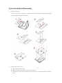
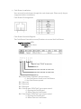
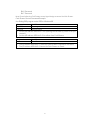
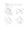
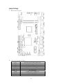
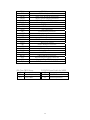
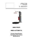
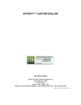
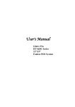
SB-9090 All-in-One System
SB-9090 All-in-One System
1
Contents
Notice ...................................................................................................... 3
Safety Information ................................................................................. 3
Caution on Lithium Batteries ................................................................. 3
Legislation and Weee Symbol ................................................................. 4
Package Contents ................................................................................... 4
System Assembly and Disassembly......................................................... 5
Open the System ......................................................................................5
Replace HDD..............................................................................................5
Security Screws.........................................................................................6
Customer Display Installation................................................................7
Cash Drawer Installation.........................................................................8
MSR Installation.......................................................................................10
Metal Stand Installation.........................................................................11
Jump Settings.......................................................................................... 12
Serial Port Pin 9 Mode Settings .............................................................. 14
Appendix ................................................................................................. 16
Specification ........................................................................................... 17
Limited Warranty Policy ......................................................................... 18
2
Notice
‧ All Information in this manual may change without prior notice.
‧ To ensure safety operation of this product, please read the following menu
carefully before using this product.
Safety Information
‧ To disconnect the machine from the electrical power supply, turn off the power
switch and remove the power cord plug from the wall socket. The wall socket
must be easily accessible and in close proximity to the machine.
‧ Read these instructions carefully. Save these instructions for future reference.
‧ Follow all warnings and instructions marked on the product.
‧ Do not use this product near water.
‧ Do not place this product on an unstable cart, stand, or table. The product may
fall, causing serious damage to the product.
‧ Slots and openings in the cabinet and the back or bottom are provided for
ventilation to ensure reliable operation of the product and to protect it from
overheating. These openings must not be blocked or covered. The openings should
never be blocked by placing the product on a bed, sofa, rug, or other similar
surface. This product should never be placed near or over a radiator or heat
register or in a built-in installation unless proper ventilation is provided.
‧ This product should be operated from the type of power indicated on the marking
label. If you are not sure of the type of power available, consult your dealer or
local power company.
‧ Do not allow anything to rest on the power cord. Do not locate this product where
persons will walk on the cord.
‧ Never push objects of any kind into this product through cabinet slots as they
may touch dangerous voltage points or short out parts that could result in a fire
or electric shock. Never spill liquid of any kind on the product.
Caution on Lithium Batteries
There is a danger of explosion if the battery is replaced incorrectly. Replace only with
the same or equivalent type recommended by the manufacturer. Discard used
batteries according to the manufacturer’s instructions.
3
Legislation and Weee Symbol
2002/96/EC Waste Electrical and Electronic Equipment Directive on the treatment,
collection, recycling and disposal of electric and electronic devices and their
components.
The crossed dustbin symbol on the device means that it should not be disposed of
with other household wastes at the end of its working life. Instead, the device should
be taken to the waste collection centers for activation of the treatment, collection,
recycling and disposal procedure.
To prevent possible harm to the environment or human health from uncontrolled
waste disposal, please separate this from other types of wastes and recycle it
responsibly to promote the sustainable reuse of material resources.
Household users should contact either the retailer where they purchased this
product, or their local government office, for details of where and how they can take
this item for environmentally safe recycling.
Business users should contact their supplier and check the terms and conditions of
the purchase contract.
This product should not be mixed with other commercial wastes for disposal.
Package Contents
Standard Items:
1. System
2.
Driver bank CD
3.
Power adapter
4.
Power cord
Accessory items
1
2
3
Part Number
3XCC00000010
3XPP00000010
7P0000000030*
Description
Touch Screen Wipes ,20 x 15mm
SPIRAL WARPPING BANDS SWB-16,L15mm
SCREW PACK: security screws*
Screw driver
* There are the security screws and a screw driver for replacing the hard drive screws.
* Customers can replace special the screws to ensure the HDD data security.
4
Quantity
1
1
1
1
System Assembly and Disassembly
1. Open the System
To access the inside system, you need to open the system first and the procedure
of opening the system is as below:
2. Replace the Hard Drive
1) Slide out the back cover.
2) Remove the screw and pull out the hard drive.
3) Release the four round screws from the hard drive tray and replace the hard
drive.
5
4) Screw the round screws back on the hard drive tray and insert the hard drive
tray into the system hard drive slot.
5) Fix the hard drive with screw on the system.
Security Screws
These are security screws and a screw driver for
replacing the hard drive. Customers replace the
special screws to ensure hard drive security.
6
3. Customer Display Installation
1) Put the panel on the flat table & open the
I/O back cover of system.
2) Assembly the customer display hinge into
the customer display slot and fasten two
screws.
3) Connect the customer display into COM3 via
the cable management slot and adjust
COM3 voltage+12V in BIOS. (refer to Serial
Port Pin 9 Mode Settings)
4) Fasten the I/O cover into the right position
and turn the system on the right position.
7
4. Cash Drawer Installation
You can install a cash drawer through the cash drawer port. Please verify the pin
assignment before installation.
Cash Drawer Pin Assignment
Cash Drawer Controller Register.
The Cash Drawer Controller use one I/O address to control the Cash Drawer.
Register Location: A22h
Attribute: Read / Write
Size: 8bit
Bit 0: Cash Drawer “DIN bit0” pin input status.
= 1: the Cash Drawer closed or no Cash Drawer
= 0: the Cash Drawer opened
Bit 1: Reserved
Bit 2: Reserved
Bit 3: Reserved
Bit 4: Cash Drawer “DOUT bit0” pin output control.
= 1: Opening the Cash Drawer
= 0: Allow close the Cash Drawer
Bit 5: Cash Drawer “DOUT bit1” pin output control.
= 1: Opening the Cash Drawer
= 0: Allow close the Cash Drawer
8
Bit 6: Reserved
Bit 7: Reserved
Note: Please follow the Cash Drawer control signal design to control the Cash Drawer.
Cash Drawer Control Command Example
Use Debug.EXE program under DOS or Windows98
Command
Cash Drawer
O A22 10
Opening
O A22 00
Allow to close
» Set the I/O address A22h bit2 = 1 for opening Cash Drawer by “DOUT bit0” pin
controls.
» Set the I/O address A22h bit2 = 0 for allow close Cash Drawer.
Command
Cash Drawer
I A22
Check Status
» The I/O address A22h bit0 = 1 mean the Cash Drawer is opened or not exist.
» The I/O address A22h bit0 = 0 mean the Cash Drawer is closed.
9
5. MSR Installation
1) Open the right side cover of system. MSR connection is supported on the
right side.
2) Connect MSR and System connector, system connector supports PS/2
interface.
3) Fasten the MSR screw on system.
10
6. Metal Stand Installation
11
Jump Settings
1. Motherboard Layout
2. Connector & Jumper Setting
DC1
DC2
CD1
LAN1
USB1, 2
USB4, 5, 6, 7
COM1
COM2
COM3
Mini Din 4P for Power Input Port
Internal Power Input Connector
RJ11 for Cash Drawer Port
RJ45 for LAN Port
USB dual stack for USB Port
USB Connector
D-SUB 9 Pin for COM1 Port
D-SUB 9 Pin for COM1 Port
RJ48 for COM3 Port
12
COM4
PS2
SATA1
SATA2
SATA3
SPWR1, 2
IDE1
LVDS1
VGA1
CR1
AUDIO1
MIC1
LPT1
TOUCH1
PCIE1
PW1
IVT1
FAN1
FAN2
LED1
BAT1A
DIO1
JP6
SJ3
COM4 Connector
PS/2 for Keyboard Port
SATA 7 Pin for SATA1 Connector
SATA 7 Pin for SATA2 Connector
SATA 7 Pin for SATA3 Connector
Power Output for SATA HDD
PATA Connector
LCD Connector
VGA Connector
Card Reader Connector
Speaker out Connector
MIC in Connector
Printer Connector
5W Resistive Touch Connector
Mini PCI-E Socket
Power Button Connector
Inverter Connector
CPU Fan Connector
System Fan Connector
LED Connector
CMOS Battery Connector
Digital Input / Output Connector
Clear CMOS
SATA Power Enable for SATA3
JP6: Clear CMOS Setup
J6
Description
1-2
Normal operation
2-3
Clear CMOS
SJ3: SATA Power Enable for SATA3
SJ3
Description
1-2
5V SATA Power Enable
2-3
Normal operation
13
Serial Port Pin 9 Mode Settings
BIOS Main Menu
When the BIOS Main Menu is displayed, the following items can be selected. Use the
arrow keys to select items and the enter key to accept and enter the sub-menu.
Enter System Overview
Advanced Settings. Use this menu for set up super I/O configuration.
14
Select Super I/O Configuration. Use this menu for set up super I/O configuration.
Serial Port 1-4 Pin9 Mode. Enter into serial port 1- 4 Pin9 Mode and set up the options
then select the serial port 1 Pin9 mode.
Save and Exit
15
Appendix
Drivers Installation
The shipping package includes a Driver CD. You can find every individual driver and
utility that enables you to install the drivers in the Driver CD. Please insert the Driver
CD into the drive and double click on the “index.htm” to pick up the models. You can
refer to the drivers installation guide for each driver in the “Driver/Manual List”.
16
Specification
Mechanical
Dimensions
Weight
Mainboards
Intel® Atom™ Processor D410 (Single Core)
1.66GHz with L2 Cache 512KB
Desktop Management Interface (DMI)
Preboot Execution Environment (PXE)
Wake on LAN (WoL)
Advanced Configuration and Power Interface (ACPI)
1 x SO-DIMM DDRII 667, up to 2GB
System
Management
Memory
OS Support
Mess Storage
Temperature
I/O Ports
LCD Touch
Monitor
Power Supply
Certifications
Options
14.57” x 11.3” x 2.17” (W x H x D)
9.92 lbs
Windows 7, Windows POSReady 2009, WEPOS, Windows XP Pro for
Embedded, Fedora(Linux)
HDD 1 x SATA 2.5” HDD
Operating Storage
0 to 40 deg C
-20 to 60 deg C
External
1 x Mini Din 4P (DC 12V only)
DC Input
1 x RJ-11 (Power Pin 12V)
Cash Drawer
1 x Gigabit Ethernet by RJ-45
Network (LAN)
4 x USB 2.0
USB Port
3 x RS-232
Serial Port
DB-9, RS-232, Pin9 w/RI/5V/12V.
COM1/2
Selectable by BIOS
RJ-48 for VFD, RS-232, Pin10
COM3
w/RI/5V/12V. Selectable by BIOS
1 x PS/2 connector for Keyboard
PS/2 Port
1 x VGA HD15 Port
VGA Port
Internal
Card Reader (and Dallas Key) Internal Pin header for Card Reader
(and Dallas Key)
Audio
AC 97 2.0 compliant, 2W Speaker x 2
Bus Expansion
1 x Mini-PCI-E Slot
15”
TFT LCD
250 nits
Brightness
1024 x 768
Resolution
True Flat 5-Wire Resistive
Touch Screen
True Flat PCT (optional)
External adapter, DC Model: 80 Watts, Voltage: +12VDC 6.6A max.
CE, FCC, Class-A, RoHS, WEEE
MSR 3-track PS/2 I/F
Magnetic stripe reader
7-inch LCD monitor
Second display
VFD 2x20
Customer display
PS/2
MSR (and Dallas Key)
17
Limited Warranty Policy
All SB-9090 feature a three-year-limited warranty with free change in the
first year from the date of purchase. If product is determined to be
defective, we will repair or replace the product with refurbished or
remanufactured parts or components during the warranty period.
This warranty is valid only for the first consumer purchaser.
This warranty does not cover cosmetic damage or damage due to acts of
God, accident, misuse, abuse, negligence, commercial use or
modifications of, or to any part of the product.
This warranty does not cover damage due to improper operation or
maintenance (see manual), connection of improper voltage supply, or
attempted repair by anyone other than a facility authorized by us to
service the product. This warranty does not cover irregular pixel
performance on the screen, and damages result due to delivery or
improper shipping. This warranty does not cover product sold AS IS or
WITH ALL FAULTS, and failure to follow instructions supplied with the
product.
This warranty is invalid if the factory-applied serial number has been
altered or removed for the product and broken security seal.
The customer must have model number, serial number, and original
proof of purchase in the form of a bill of sales or receipt invoice, which is
evidence that the unit is within the warranty period, must be presented
to obtain warranty service. Our helpful technical support and customer
service staff will attempt to correct any minor issues that might be
causing the product failure. If the technical service or customer
representative is unable to fix the issue by phone, a return material
authorization (RMA) number will be issued. Along with the proof of
purchase and the RMA number, the customer can ship the defective unit
back to us Once the defective unit is received, and tested, we will ship a
replacement unit back to customer. It is the responsibility of the
customer to properly package the monitor with plugs, power supply, etc.
We shall not be liable for the loss of the use of the product,
inconvenience, loss or any other damages, direct or consequential, arising
out of the use of, inability to use, or any claim against the customer by
any other party. Some regions do not allow exclusion of incidental or
consequential damages, so the above limitations and exclusions may not
apply to you.
18
SB-9090 All-in-One System
19