1
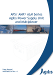
DS 'B' Series Door Station User Manual Revision: 50 Applies to Rev 3 and Rev 4 Hardware loaded with Software Version 6.16 or higher Revision: 50 Copyright 2011 NF Communications Designed and Manufactured in Australia by NF Communications P/L Anthony Street Ormond VIC 3204 Tel: 03 9532 5112 Fax: 03 9576 8521 Web: www.nfcomms.com.au Page 1 of 8 DS 'B' Series Door Station User Manual Page 2 of 8 Revision: 50 DS 'B' Series Door Station User Manual Revision: 50 1 Introduction The DS Series Door Station series is intended as a hands free speaker telephone situated at a door or gate and is connected to a suitable analogue extension of a PABX or key system, such as the Premier SOHO PABX. Pressing the button of the Door phone will initiate the automatic sending of a DTMF number sequence which will be analysed and handled by the PABX. The DS ‘B’ Series is suitable for flush mounting in any wall with a cavity about the size of half a standard house brick. A surface mounting bracket option is available. 2 Features - Sealed to IP54 for protection against rain, water splashes and dust. - Voice circuit is Line powered, so main function will still work if external power fails. - External plug pack power required for Door strike and optional camera. - Stainless Steel, Anodised Aluminium or Brass front panel options. - Multiple button model to access different areas. - Anti vandal construction - Flush or Surface mount - Electronic control of Volume and Microphone sensitivity to adjust unit to local environments - Improved Busy tone detection to suit most PABX types 3 Compliance The DS ‘B’ series Door Station is fully approved and meets the Australian Communications Authority (ACA) requirements for Electrical Safety, Telecommunications and Electromagnetic Compatibility (EMC). Warning: The DS ‘B’ Series Door Station has been designed for connection to a PABX and is not approved or intended for direct connection to the Public Switched Telephone Network (PSTN). 4 Installation 4.1 Mounting the Front panel. Flush mount units should be fitted in a cavity size as specified and fixed using wall plugs or other suitable fixings. Suggested hardware is 25X6mm wall plugs and 8G stainless steel “tamper torx” screws, which can be supplied on request. Refer to separate instructions supplied with the various brass and stainless steel front panels, surface mount brackets and plastic units. 4.2 Power Supply. The telephone section of the Door Station is Line Powered from the telephone line. If fitted, the Door Station relay driver and LED will require 15 to 28V DC (unregulated) power. Page 3 of 8 DS 'B' Series Door Station User Manual Revision: 50 The power input can be provided from the extension ports of the Premier PABX itself (pair 2 power), or from a plug pack. The Premier’s auxiliary power feed can be used to power both the Door Station’s LEDs and an optional Door Strike coil, provided the Door Strike coil needs less than 400mA at 12V. There is insufficient power from the Premier to feed the DS Series with the Camera option so an external plug pack is required if the camera option is fitted. Summary of Power requirements: Hands free Telephone Door Relay + LED Door Relay + LED + Camera Connection Through PSTN or PABX line Orange Pair, non polarized Orange Pair, non polarized Voltage Line Powered (nominal 48V or 24V) 15-28VDC 15-28VDC Current Line Powered (nominal 25mA) 400mA minimum 800mA minimum 4.3 Set up. Various parameters on the DS ‘B’ Series can be programmed – refer section 5. The DS ‘B’ series Door Station by default sends the DTMF sequence #27 when the Door Button is pressed (and #28 if the 2nd button is pressed on 2 button models). If connected to the Premier SOHO PABX, all telephone extensions will ring when #27 or #28 is dialled. The Premier will need to be programmed if selected extensions are required to ring. Refer to Premier Programming manual for information on how to program selective ringing for extensions. 4.4 Door Strike. A door strike coil can be connected directly to the brown pair. When key 2 is pressed (programmable) on the remote telephone, upto 12VDC at upto 400mA will be provided to the Door strike coil, for 3 seconds (programmable). Independent contacts are also controlled by the Door Strike operation. The Door Latch code and the duration of the relay ON time can be programmed – see command list. 4.5 Volume and Microphone sensitivity Adjustment. Both Volume and Microphone sensitivity can be adjusted remotely by command. Also, the balance between the strength of the signal from the line or the microphone can be adjusted. These commands allow the unit’s parameters to be tuned to suit the site’s acoustic environment. 4.6 Automatic Answer for Parallel connected Units. Units can be connected in parallel to share the same line. For incoming calls, the units can be configured so that both units will automatically answer the call, rather than only one at random. Contact NFcomms for details. 4.7 Cabling. The Door Station cabling should be installed according to AS/NZ 3086 “Telecommunications Installations – Integrated telecommunications cabling systems for small office/home office premises”. If the Cable Tail wires will be subjected to weather conditions, they should be connected using silicon filled telecom insulation displacement connectors, to ensure weather proofing of the connections. Page 4 of 8 DS 'B' Series Door Station User Manual Blue/white Blue Line Line 1 Orange Power GND 2 Orange/wh Power IN +15 to 28VDC 5 Green Common 6 Brown/ white NC contact 4 Green/ white NO contact Brown Power OUT to Door strike To PABX + From plug pack or Premier Pair 2 Uncommitted contacts. These switch when Relay Code is entered +12V 3 Revision: 50 +12V appears on Brown wire when Relay Code entered Pins 1 & 2 (Orange Pair): Power for the unit can be supplied: (1) directly from the Premier PABX via pair 2 of the Premier’s modular (RJ12) extension port. The inner pair (pair 1) of the modular connector (RJ12) plug is the extension line pair. Fig 1. Premier PABX Extension port viewed from front with contacts at bottom 6 5 4 3 2 1 (2) or from a 15 to 28V DC 500mA plug pack. NC NC Pair 1 Pin 1 (Orange) is the common Power GROUND Pair 2 DC Power pin 5=negpin 2=pos+ Pin 2 (Orange/White) is +15 to 28V DC input power Note: The voice circuit of the Door Station is line powered and will operate without external power. The power on Pins 1 & 2 is only required to supply power to the button LED, the Door relay and external Door Strike coil, and optional camera if fitted – if none of these features is used, power on Pins 1 & 2 is not required. Pin 3 (Brown wire): Provides a nominal +12V to a door solenoid when the Door Relay code is applied. Other terminal of solenoid must be connected to the Power ground (Pin 1 or Orange). Pin 3 is protected from temporary accidental shorting. Pins 4 & 5 (Green Pair): Uncommitted contacts. Normally Open (NO). These contacts CLOSE when the Door Relay code is applied. These contacts are rated at 1A 30VDC. Pin 5 (Green wire) and Pin 6 (Brown/white wire): Uncommitted contacts. Normally Closed (NC) These contacts OPEN when the Door Relay code is applied. These contacts are rated at 1A 30VDC. Blue LINE pair: Voice Line pair. Note: If using the Premier SOHO PABX, the Door Station can be connected to any extension of the Premier, however it is suggested that extension 8 not be used for the Door Station as this should be reserved for the emergency access telephone for use when power fails. Refer to the Premier User Manual. Page 5 of 8 Pair 1 Line pin 4=L+ pin 3=L- DS 'B' Series Door Station User Manual Revision: 50 5 Programming Various parameters can be programmed on the DS series Door Stations. 5.1 Initiating a connection to the Door Station. To start a programming session, a connection must be made between a standard DTMF telephone and the Door Station through a PABX. Connect the Door Station to one extension of a PABX, and a standard DTMF capable telephone to another extension. Use the standard DTMF capable telephone and call the Door Station. The default setting for the Door Station is to automatically answer an incoming call. The Door Station can be programmed to manually answer an incoming call by pressing the button – see command *6. Commands are entered using DTMF tones to change the parameters. 5.2 Administration mode. Enter the Admin Mode by entering the command *#1234#. The default Access Code is 1234 and can be changed if required. The LED will flash faster than normal to indicate Admin Mode. NOTE: All commands that require a new value to be stored will need to be entered in Admin Mode. Other commands such as Read Software Version (*82) can be entered without going into Admin Mode. 5.3 Entering Commands. Commands are started with *. Successful commands are acknowledged with 2 short beeps. Failed commands are indicated by 1 long beep. For commands that read values, beeps count out each digit. One low tone represents 0. For example, 405 sounds out with 4 beeps, quiet, 1 low beep, quiet, 5 beeps. DTMF Command *1b nnnn # Description Destination Numbers Change the number sent when call button b is pressed. b is the button number (1 to 5 where fitted). nnnn is the destination number and can be 0 to 15 digits long. Note: To enter a pause or special characters into the digit string use prefix * as detailed below. Eg. *110*1395251234# means that when button 1 is pressed, the digits 0395251234 will be dialled, with a 1 sec pause after the 0 digit. To loop line without sending digits, set nnnn blank, for example *12# means that when button 2 is pressed, the line will be looped but no digits will be sent. *2 Access Codes and Limits *200 *201 *21 eeee # *22 eeee # *23 eeee # *24 eeee # *25 eeee # *28 nnn *29 aaaa Set *2 range of commands to FACTORY DEFAULT Disable all Keypad Door Relay Activation Codes Keypad Door Relay Activation Code 1 (eeee is 4 to 6 digits) Keypad Door Relay Activation Code 2 (eeee is 4 to 6 digits) Keypad Door Relay Activation Code 3 (eeee is 4 to 6 digits) Keypad Door Relay Activation Code 4 (eeee is 4 to 6 digits) Keypad Door Relay Activation Code 5 (eeee is 4 to 6 digits) Set Keypad DTMF allowable dial length, (Default 4, Phone Point 255) Change Administration Access Code (Default 1234) *3 Timer Configuration *30 *31 m *32 ss *33 ss Set all timer values to FACTORY DEFAULT Call Duration Time in minutes: 0 to 9 (Default 4 min, 0 = no timeout, example *314#) Door Relay ON Time in seconds: 0 to 30 (Default 4 sec, example *324#) Button Dial Out Delay in 0.1 secs: 0 to 99. (Default 0, eg. *330#) Page 6 of 8 DS 'B' Series Door Station User Manual DTMF Command Revision: 50 Description *4 DTMF Only Access Codes. Enter from remote telephone. *41 nn *42 nn *43 x Door Relay Activation Code (Default 2 example *412#) Hangup Code (Default 99, example *4299#) Parallel Mode ONLY. Units that match Identifier (x = 0-9) will stay ONLINE and change to SINGLE MODE. All non-matching units will hangup. *5 Answer Tone (Tone that sounds when call is answered) and Ringer Volume *510 *511 *512 *513 *514 *515 *516 *52 x No tone on answer Set Answer Tone to Tone 1 Set Answer Tone to Tone 2 Set Answer Tone to Tone 3 (Default) Set Answer Tone to Tone 4 Set Answer Tone to Tone 5 Set Answer Tone to Tone 6 Ringer volume (See *750 command). 0=OFF, 1=Low, 2=High (Default *522) *6 Dynamic Operational Characteristics *60 *61 x *6# Set all dynamic parameters (*6 commands) to FACTORY DEFAULT Control LLC, LIV and Background Noise (BGN) x = 0 to 7 - Control LLC and LIV only x = 8 - Disable BGN (No change to LLC, LIV) x = 9 - Enable BGN as defined by setting provided in *69xx Set minimum dial tone detection time, 0 to 9 sec (Default 2 sec, example *622) Set microphone sensitivity: 0 low, 9 high. (Default 5, example *635) Set microphone sensitivity boost for parallel mode (0-9, default = 3) Set speaker boost for parallel mode (0-9, default =3) Busy tone detection. (x=0 default, x=1 Fiji, x=3 Panasonic) Set speaker volume: 0 low, 9 high. (Default 5, example *675) Set balance between mic and speaker: 0 most emphasis on mic. (Default 5, ex *685) Set BGN level and Hands Free switching speed. nn=0 to 15. Contact NFcomms for details. For example: nn=00 BGN 120mv MAX switching speed, Nn=08 BGN 240mv MAX switching speed Read settings *7 Feature Control *70 Set all Features (*7 commands) to FACTORY DEFAULT (default settings are highlighted) FLASH LED during call (0=Solid, 1=Flash LED during a call) Enable Busy Tone detection (0=Enable, 1=Disable) Keypad (0=Not installed, 1=Installed, default set for appropriate model) Multi LED (0=Single LED only, 1=Multi LED, default set for appropriate model) Answer Mode (0=Manual Answer, 1=Auto Answer) Single/Parallel Mode (0=Single mode, 1=Parallel mode) Door Relay Tone when activated (0=Silence, 1=Beeps) Door Relay Mode (0=Normally OFF, 1=Normally ON) Read settings *62 n *63 n *64 n *65 n *66 n *67 n *68 n *69 nn *71 n *72 n *73 n *74 n *75 n *76 n *77 n *78 n *7# Page 7 of 8 DS 'B' Series Door Station User Manual DTMF Command Revision: 50 Description *8 Immediate Action *80 *81 *82 *83 *84 *85 *86 *87 *88 *89 xxx Turn Door Relay OFF Turn Door Relay ON Sound firmware version (3 digits, beeps count out each digit, digit 0 is one low tone) Sound the value of the Call Duration setting Sound the value of the unit’s STATUS Sound the value of the Option setting Control the state of the Test Ringer Sound the value of the Flash Option setting Sound ring loop counter Send a command to the controller *9 Administration Commands *91 *92 *96 x *97 *98 *#aaaa# Read Serial Number Read Administration Unlock Key (used by Factory to generate Reset Code) Set Identifier (x=0-9, default = 1) PARALLEL MODE ONLY Set the Serial Number (Factory set) Enter Administration Reset Code (contact Factory to assist with forgotten Access Code) Enter Administration Mode. aaaa is Access Code (Default 1234) (Enter this command from a remote phone or from Keypad if fitted) User Operational Commands from Keypad (Keypad model only) *eeee Operate Door Relay (Press Call button first). eeee is the 4 to 6 digit Door Relay Activation Code set with the *2 command. Hangup will occur at completion of door release. To stop fraudulent door entry attempts, the Door Station will delay hanging up for 60s after 3 or more successive incorrect attempts have been made. Once a correct Activation Code is made, the Door Station will revert to normal operation. dddd Press Call button first , then Dial Extension (dddd is the extension number to be called, length limited by *28 command) Dial string command *1b To enter digits, special characters and pauses into the dial string, use the following DTMF keys on the telephone. Enter * prefix to enter a special character. Enter # to terminate the string entry. Item to enter in Enter this For example, consider dial string dial string code “098761234” for button 1. Premier PABX 1 2 3 . . 8 9 * # 1 second pause 2 second pause DTMF A DTMF B DTMF C DTMF D 1 2 3 . . 8 9 ** *# *1 *2 *4 *5 *6 *7 To store this string for button 1 with a 2 second pause after the digit 0, enter the following command: *110*298761234# The 8 RJ12 extension ports of the Premier PABX Page 8 of 8