1
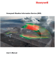
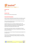
DS Series Door Station User Manual Revision: 22 For Hardware Rev 3a or higher Revision: 22 Copyright 2008 NF Communications Designed and Manufactured in Australia by NF Communications P/L Anthony Street Ormond VIC 3204 Tel: 03 9525 7195 Fax: 03 9525 7196 Web: www.nfcomms.com.au Page 1 of 8 DS Series Door Station User Manual Page 2 of 8 Revision: 22 DS Series Door Station User Manual Revision: 22 1 Introduction The DS Series Door Station series is intended as a hands free speaker telephone situated at a door or gate and is connected to a suitable analogue extension of a PABX or key system, such as the Datis Hitec Premier SOHO PABX. Pressing the button of the Door phone will initiate the automatic sending of a DTMF number sequence which will be analysed and handled by the PABX. The DS Series is suitable for flush mounting in any wall with a cavity about the size of half a standard house brick. A surface mounting bracket option is available. 2 Features - Sealed to IP54 for protection against rain, water splashes and dust. - Voice circuit is Line powered, so main function will still work if external power fails. - External plug pack power required for Door strike and optional camera. - Stainless Steel or Brass front panel options. - Multiple button model to access different areas. - Anti vandal construction - Flush or Surface mount - Electronic control of Volume and Microphone sensitivity to adjust unit to local environments - Improved Busy tone detection to suit most PABX types 3 Compliance The DS series Door Station is fully approved and meets the Australian Communications Authority (ACA) requirements for Electrical Safety, Telecommunications and Electromagnetic Compatibility (EMC). Warning: The DS Series Door Station has been designed for connection to a PABX and is not approved or intended for direct connection to the Public Switched Telephone Network (PSTN). Page 3 of 8 DS Series Door Station User Manual Revision: 22 4 Installation 4.1 Mounting the Front panel. Flush mount units should be fitted in a cavity size as specified and fixed using wall plugs or other suitable fixings. Suggested hardware is 25X6mm wall plugs and 8G stainless steel “tamper torx” screws, which can be supplied on request. Refer to separate instructions supplied with the various brass and stainless steel front panels, surface mount brackets and plastic units. 4.2 Power Supply. The telephone section of the Door Station is Line Powered from the telephone line. The Door Station will need to charge up when first connected to the line – this may take upto 30 seconds. This charge will remain for a few days if removed from the line. The Door Station relay driver and LED will require 15 to 24V DC (unregulated) power or 15VAC power, rated at 500mA. This can be provided from the extension ports of the Premier PABX itself (pair 2 power), or from a plug pack. The Premier’s auxiliary power feed can be used to power both the Door Station’s LEDs and an optional Door Strike coil, provided the Door Strike coil needs less than 400mA at 12V. There is insufficient power from the Premier to feed the DS Series with the Camera option so an external plug pack is required if the camera option is fitted. Summary of Power requirements: Hands free Telephone Door Relay + LED Door Relay + LED + Camera Connection Through PSTN or PABX line Orange Pair, non polarized Orange Pair, non polarized Voltage Line Powered (nominal 48V or 24V) 15-24VDC or 15VAC 15-24VDC or 15VAC Current Line Powered (nominal 25mA) 400mA minimum 800mA minimum 4.3 Set up. Various parameters on the DS Series can be Programmed – refer section 4. The DS Series Door Station by default sends the DTMF sequence #27 when the Door Button is pressed (and #28 if the 2nd button is pressed on 2 button models). If connected to the Datis Hitec Premier SOHO PABX, all telephone extensions will ring when #27 or #28 is dialled. The Premier will need to be programmed if selected extensions are required to ring. Refer to Premier Programming manual for information on how to program selective ringing for extensions. 4.4 Door Strike. A door strike coil can be connected directly to the brown pair. When key 2 is pressed (programmable) on the remote telephone, upto 12VDC at upto 400mA will be provided to the Door strike coil, for 3 seconds (programmable). Independent contacts on the Green pair are also controlled by the Door Strike operation. The Door Latch code and the duration of the relay ON time can be programmed – see command list. Page 4 of 8 DS Series Door Station User Manual 4.5 Revision: 22 Cabling. The Door Station cabling should be installed according to AS/NZ 3086 “Telecommunications Installations – Integrated telecommunications cabling systems for small office/home office premises”. If the Cable Tail wires will be subjected to weather conditions, they should be connected using silicon filled telecom insulation displacement connectors, to ensure weather proofing of the connections. 8 7 6 Blue/white Blue Orange/ white Line Line 5 Orange Power 4 Green/ white Common Green NO switch To PABX To plug pack or Premier Pair 2 Power Uncommitted contacts 3 +12V 2 1 Brown +12V to Door strike Brown/ white Door Strike return To Door Strike coil Brown Pair: Door Latch relay contacts. These terminals provide a nominal 10-12V 450mA DC supply to operate a Door Latch coil when the Door Latch code is sent. These terminals can be connected directly to a door latch coil. These terminals are protected from temporary accidental shorting. NOTE: Internal strap must be fitted. Green Pair: Uncommitted Normally Open (NO) contacts. Door Latch relay contacts that operate when the Door latch code is sent. These contacts are rated at 1A 30VDC. NOTE: Internal strap must be removed (unit is Fig 1. Premier PABX Extension port viewed from delivered with strap removed). front with contacts at bottom Orange Power Pair: Power for the unit can be supplied: 6 (1) directly from the Premier PABX via pair 2 of the Premier’s modular (RJ12) extension port. The inner pair (pair 1) of the modular connector (RJ12) plug is the extension line pair. (2) or from a 15 to 24V DC or 16-18V AC 500mA plug pack. 5 4 3 2 NC 1 Pair 1 Line pin 4=L+ pin 3=L- NC Pair 1 Pair 2 DC Power pin 5=negpin 2=pos+ The Door Station power terminals are non polarized – the DC cables can be connected either way. Note: The voice circuit of the Door Station is line powered and will operate without external power. The Plug pack power is required only to supply power to the LED and the Door relay and external Door Strike coil, and optional camera if fitted. Page 5 of 8 DS Series Door Station User Manual Revision: 22 Blue LINE pair: Voice Line pair. Connect a category 5 cable between the Front panel unit and the PABX. The cable can pass through the premises’ Distribution Device (DD). Note: If using the Premier SOHO PABX, the Door Station can be connected to any extension of the Premier, however it is suggested that extension 8 not be used for the Door Station as this should be reserved for the emergency access telephone for use when power fails. Refer to the Premier User Manual. Premier PABX Fig 2: The 8 RJ12 extension ports of the Premier PABX 4.6 Volume and Microphone sensitivity Adjustment. Both Volume and Microphone sensitivity can be adjusted remotely by command. This allows the unit’s parameters to be tuned to suit the environment that it is in. 5 Programming Various parameters can be programmed on the DS series Door Stations. A call must be made into the unit with a standard analogue DTMF capable telephone. The unit must have the answer strap fitted to answer the call. Commands can then be entered using the telephone buttons to change the parameters. Changes survive power down. Commands are started with *. Successful commands are acknowledged with 2 short beeps. Failed commands or actions are indicated by 1 long beep. Page 6 of 8 DS Series Door Station User Manual Revision: 22 Command DTMF codes Example Comment Default Door Relay ON time *0 XX# *0 10# *0 4# Door Relay ON time in seconds. 1 to 29 secs 4 seconds Change Destination number *1 nnnn# *10395251234# Change the number sent when call button 1 is pressed. nnnn is 1 to 15 digits long. Note: to enter a # in the Destination number use the * button – cannot use the # button because this will end the entry. #27 Change Destination number *2 nnnn# *2*28# Change the number sent when call button 2 pressed. nnnn is 1 to 15 digits long. Note: to enter a # in the Destination number use the * button – cannot use the # button because this will end the entry. #28 Change Call Duration time *3 x *34 Call automatically clears after x minutes. x is 0 to 9 minutes. 0 indicates no timeout. 4 minutes Change Door Relay code *4 DD# *42# DD is a 1 or 2 digit code, using digits 0-9. Code DD can be entered during any call to activate the Door Relay 2 Tone on Answer *5 <option> *51 <option> is the cadence of the tone on answer selection. 0 selects no tone on answer 1 (tone on answer) Level Control and Answer Mode *6 <option> <level> *675 *60 Default is x=3 for each setting This example will store the digits #28 for button 2. Set *6 options to default values *63x Sets Microphone sensitivity to x x = 0 is lowest sensitivity x = 7 is highest sensitivity *67x Sets volume level of speaker to x x = 0 is lowest volume x = 7 is highest volume *68x Sets balance between speaker & microphone x = 0 most emphasis on mic x = 7 most emphasis on speaker *65x Sets Answer Mode x = 0 Manual answer via Call Button x = 1 Automatic answer (default) Page 7 of 8 DS Series Door Station User Manual Revision: 22 Command DTMF codes Example Comment Options *7 <option> *70 Button Flash Option: *70 – no button LED flash *71 – flash button LED when call active Busy tone Hangup Option: *72 – hangup if busy tone detected *73 – ignore busy tone Door Relay tone: *76 – No tone when Door relay on. *77 – Tone when Door relay on. Door Relay option: *78 – Door Relay ON always when ONLINE *79 – Door relay operates on Door code Immediate Action *8 x *82 *80 – Deactivate Door Relay *81 – Activate Door Relay *82 – Sound software version Hangup *9 *9 Causes the Door Station to hangup Note: Door Station also disconnects on code 99 and in response to DTMF “B” and “C” tones. Page 8 of 8 Default *71 *72 *77 *79