1
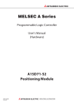
MPO-02 Device for measuring and control of protective circuits User Manual ELECTRON Prešov MPO-02 is a measuring device which serves to measure low resistance, and the voltage drop across the protection circuit to the alternating current of more than 10 A AC. The device allows to determine the exact value of resistance of the protective circuit and voltage drop at the protective circuit according to the cross-section of protective conductor. The device allows you to set a cross-section of protective conductor to the extent provided STN / IEC 60204-1. Exceeding the values as specified by that standard, the alarm will alert the illegal value. Caution!!! Before you start using the machine please read this User Manual. If there is not ensured safe operation of the device, it is necessary to shut down and lock the device against the accidental use. Do not connect the device to the measured object while the measuring button is pressed. Do not move measuring inputs of the device from the measuring object until the moment that the green light lights up which signalizes the devices status. Do not use the device, if: - the device is obviously damaged - the device does not work according to this Manual - the device has been exposed to adverse weather conditions for a long period of time. Do not open the device as it infringes service seals and thus loses the right to free warranty service! Operating and Display Elements An outline of the measuring instrument MPO-02: 1. The inlet power cord of the measuring device 2. Measuring button of the device 3. Mobile measuring input 4. Fixed test probe 5. Timer light 6. Mode switch - Ω – V 7. Select button protective conductor cross-sections MODE 8. Display LCD Basic Instructions for The User After switching the device on the network, the green light of the Timer lights up (5), indicating that the measuring device is connected to a network and does not take the measurement. Measurement is triggered by short-pressing the measuring button (2) on the handle of the device. Leaving the measuring button pressed for more than 10 seconds, Er - t (Error button) will be displayed. The measurement takes place while the light of the timer is off (5) which indicates that the circuit measuring current flows. It is necessary to measure up to the point until the green light lights up (Timer (5)) on the rear (approx 10 sec.), as if you move solid measuring tip from the measured electrical devices earlier, it may experience the unwanted tanning. Do not connect the measuring device leads to the measured object while holding down the measuring button (2). By MODE selector button the measurements of protective circuits for the following crosssection can be selected: 6,0mm², 4,0mm², 1,0mm² and 2,5mm²1,5mm². According to ČSN EN 60 204-1 safety circuit must comply with the conditions set out in the following table: The smallest cross section of the protective conductor test branch circuit (mm2) 1,0 1,5 2,5 4,0 6,0 Allowed voltage drop (V) 3,3 2,6 1,9 1,4 1,0 An appropriate protection circuit resistance (Ω) 0,33 0,26 0,19 0,14 0,1 Measurement Mode Ω Switch Mode switch (6) to Ω. Retract into to the socket (230 V, 50 Hz) the power cord of the measuring device (1). On the rear of the device lights up the green light of the Timer (5). The display shows the resistance measurement of the protective circuit in cross-section 6.0 mm². Movable measurement input (3) fasten to the protective connector PE of the measured electric object and by the device tip (4) connect to the various points which are the part of the protective circuit. Measuring itself takes place by short pressing the measuring button (2) on the handle of the device. During the measurement, the green light is off (TIMER (5)), indicating that the circuit measuring current flows. The measurement process will automatically turn off after approximately 10 seconds, signaling the re-lighting of the green LED TIMER (5) at the rear. Do not move solid measuring tip from the measured electric device during the measurement as it may experience the unwanted tanning. On the output display (8) remains measured resistance value approximately three seconds and then again appears set value of the cable cross section. Selection of the various protective conductor cross-sections is performed using the selecting button MODE (7). After its pressing and holding for approximately 1 second are successively elected various protective conductor cross-sections. Selection of different cross-sections is signaled acoustically. If the resistance value of the protection circuit for set protective conductor cross-section exceeds permitted value by STN/ČSN 60 204-1 (see table), the device with an audible alarm warns the illegal value of the resistance. Resistance value greater than the highest value of the measuring range, i.e. higher than 1,999 Ohm is indicated on the display by illumination of eights – 8888. Measurement Mode V Switch Mode switch (6) to V. Retract into to the socket (230 V, 50 Hz) the power cord of the measuring device (1). On the rear of the device lights up the green light of the Timer (5). The display shows the voltage drop on the protective circuit in cross-section 6.0 mm². Movable measurement input (3) fasten to the protective connector PE of the measured electric object and by the device tip (4) connect to the various points which are the part of the protective circuit. Measuring itself takes place by short pressing the measuring button (2) on the handle of the device. During the measurement, the green light is off (TIMER (5)), indicating that the circuit measuring current flows. The measurement process will automatically turn off after approximately 10 seconds, signaling the re-lighting of the green LED TIMER (5) at the rear. Do not move solid measuring tip from the measured electric device during the measurement as it may experience the unwanted tanning. On the output display (8) remains measured resistance value approximately three seconds and then again appears set value of the cable cross section. Selection of the various protective conductor cross-sections is performed using the selecting button MODE (7). After its pressing and holding for approximately 1 second are successively elected various protective conductor cross-sections. Selection of different cross-sections is signaled acoustically. If the value of the voltage drop on the protection circuit for set protective conductor crosssection exceeds permitted value by STN/ČSN 60 204-1 (see table), the device with an audible alarm warns the illegal value of voltage. Voltage value greater than the highest value of the measuring range, i.e. higher than 5,000 V is indicated on the display by illumination of eights – 8888. Basic Technical Parameters Supply Voltage: 230 V, 50 Hz Measuring current: min. 10 A, AC Input power: 70 – 250 VA Output Voltage: max. 6V, 50 Hz Measuring time: app. 10 seconds Resistance measuring range: 0,000 – 1,999 Ω The resolution when measuring resistance: 0,001 Ω Resistance measuring accuracy: 1,5% + 4 digits The measuring range of the voltage drop: 0,000 – 5,000 V The resolution at voltage drop: 0,001 V Voltage drop measuring accuracy: 1,5% + 4 digits Weight of the device: app. 1,2 kg ELECTRON spol. s r.o. Jelšová 24 080 05 Prešov Slovenská republika tel. 051 – 77 230 79 fax. 051 – 77 230 79 www.electron.sk [email protected]