1
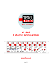
ML–118 Mastering Mid-Side Unit User Manual Issue 0.2 ARREL Audio ML-118 User Manual, Issue 0.2 Page 2 ARREL Audio SAFETY INSTRUCTIONS WARNING Always follow the precautions listed below to avoid any possibility of serious injury or even death from electrical shock, shortcircuiting, damages, fire or other hazards. These precautions include, but are not limited to, the following: Do not expose the instrument to liquids and rain. Do not use it near water or in damp or wet conditions, or place containers on it containing liquids. If any liquid seeps turn off the power and unplug the power cord from the AC outlet. Do not put burning items, such as candles, on the unit. A burning item may fall over and cause a fire. This instrument contains no user-serviceable parts. Do not open the instrument or attempt to disassemble or modify the internal circuit. Never insert or remove an electric plug with wet hands. Check the electric plug periodically and remove any dirt or dust which may have accumulated on it. Do not place the power cord near heat sources such as heaters or radiators, and do not excessively bend or otherwise damage the cord, place heavy objects on it, or place it in a position where anyone could walk on, trip over, or roll anything over it. CAUTION Always follow the precautions listed below to avoid any possibility of serious injury or even death from electrical shock, shortcircuiting, damages, fire or other hazards. These precautions include, but are not limited to, the following: Do not connect the instrument to an electrical outlet using a multiple-connector. Doing so can result in lower sound quality, or possibly cause overheating in the outlet itself. When removing the electric plug from the instrument or an outlet, hold the plug itself and not the cord. Pulling by the cord can damage it. Remove the electric plug from the outlet when the instrument is not to be used for extended periods of time, or during electrical storms. Do not place the instrument in an unstable position where it might accidentally fall over. Before moving the instrument, remove all connected cables. When setting up the product, make sure that the AC outlet you are using is easily accessible. If some trouble or malfunction occurs, immediately turn off the power switch and disconnect the plug from the outlet. Even when the power switch is turned off, electricity is still flowing to the product at the minimum level. When you are not using the product for a long time, make sure to unplug the power cord from the wall AC outlet. Use only the stand/rack specified for the instrument. When attaching the stand or rack, use the provided screws only. Failure to do so could cause damage to the internal components or result in the instrument falling over. Information for Users on Collection and Disposal of Old Equipment This special symbol on the products, packaging, and/or accompanying documents means that used electrical and electronic products should not be mixed with general household waste. For proper treatment, recovery and recycling of old products, please take them to applicable collection points, in accordance with your national legislation and the Directives 2002/96/EC. By disposing of these products correctly, you will help to save valuable resources and prevent any potential negative effects on human health and the environment which could otherwise arise from inappropriate waste handling. For more information about collection and recycling of old products, please contact your local municipality, your waste disposal service or the point of sale where you purchased the items. [For business users in the European Union] If you wish to discard electrical and electronic equipment, please contact your dealer or supplier for further information. [Information on Disposal in other Countries outside the European Union] This symbol is only valid in the European Union. If you wish to discard these items, please contact your local authorities or dealer and ask for the correct method of disposal. ML-118 User Manual, Issue 0.2 Page 3 ARREL Audio ARREL Audio Contacts ARREL Audio Via A. Mondadori, 7 00128 Rome – Italy Tel +39 06 506 2017 Fax: +39 06 5062017 Info: [email protected] Web: www.arrel-audio.com Support: http://www.arrel-audio.com/support ARREL Audio is continuously working to the improvement of its systems and related documentation. In any case, we reserve the right to change the specifications without notice but in respect to the current legislation. Disclaimer: The information contained in this manual has been carefully checked and we believed is accurate at the time of publication. In any case, we do not assume any responsibility for inaccuracies, errors or omissions nor any liability for any loss or damage resulting either directly or indirectly from use of the information contained in this manual. ML-118 User Manual, Issue 0.2 Page 4 ARREL Audio TABLE OF CONTENTS SAFETY INSTRUCTIONS ................................................................................................... 3 ARREL Audio Contacts ........................................................................................................ 4 TABLE OF CONTENTS ....................................................................................................... 5 INTRODUCTION ................................................................................................................. 6 Housing and Rack Mounting ................................................................................................ 7 ML-118 FRONT PANEL CONTROLS AND OPERATIONS .................................................. 8 INPUT stage ..................................................................................................................... 8 CODING SECTION .......................................................................................................... 9 FILTER Section .............................................................................................................. 10 INSERT section .............................................................................................................. 11 PHASE REVERSE ......................................................................................................... 14 DRY-WET ....................................................................................................................... 15 OUTPUT LEVEL ............................................................................................................ 15 STEREO OUT ................................................................................................................ 15 MONITOR ...................................................................................................................... 16 MUTE Function .............................................................................................................. 16 STEREO Mode BUTTON ............................................................................................... 16 APPENDIX A: External connections .................................................................................. 18 APPENDIX B: Front Panel ................................................................................................. 20 APPENDIX C: Back Panel ................................................................................................. 21 APPENDIX D: BLOCK DIAGRAM ..................................................................................... 22 APPENDIX E: Stereo Mode Applications ........................................................................... 23 TECHNICAL SPECIFICATIONS ........................................................................................ 27 ML-118 User Manual, Issue 0.2 Page 5 ARREL Audio INTRODUCTION The ARREL Audio ML-118 is a new MID-SIDE unit characterized by an outstanding sound quality and a number of new functions that are not available on other MID-SIDE units available on the market. The ML-118 is an advanced Mid/Side analog processor designed by ARREL Audio to comply with the demands of professional recording and mastering engineers. Mid/Side processing is based on the coding of a stereo signal into two components. The “Mid” channel contains the information that appears in both the left and right channels, and the “Side" channel contains all the information that differs between the left and right channels. Once encoded into M/S, these two signals can be processed independently, before being decoded back into L and R channels. The M/S technique gives more control over the width of the stereo image than techniques based on microphone placement techniques. The Monster MS is a code/decode mono/stereo system to be used primarily for mastering sessions but it will perform outstandingly also as a stereo effects unit and as a mastering console. On top of its amazing sound quality, the Monster MS unit features a unique set of functions never seen before in similar units. The L+R and L-R channels are equalized in amplitude by suitable gains at +4 dBu in order to obtain the maximum Signal/Noise ratio and the optimum headroom in the audio path. This fact is important when compressors/limiters are used as inserts in the MID-SIZE audio path. Each L+R and L-R processing section contains a HI-PASS and a LO-PASS filter that can be selected by pressing the HI-PASS/LO-PASS button. The filters are characterized by two working bands selected by pressing the corresponding buttons (Fx10 and Fx4), the cut off frequency is adjustable by a potentiometer. HI-PASS filter parameters: Range 20-250 Hz or 200-2500 Hz (F x 10 button pressed). LOPASS filter parameters: Range 1-5 KHz or 4-20 KHz (F x 4 pressed). The filters slope is 12dB/Oct. Three INSERT points are available to connect outboards. INSERT 1 and 2 are available on the DB-25 connector on the back panel. This connection is useful for effects that are often used in the audio path. INSERT 3 connectors are located on the front panel (XLR connectors). This is useful for on the fly outboard connections. The unit provides a Phase Inversion button to reverse the phase of the wet signal (addition and subtraction of the effect). The wet and dry signals can be mixed together. A bypass switch (illuminated by a LED) can turn the device into a Stereo unit, making the Monster MS an effects unit perfectly integrated in an external signal processing chain. The Monster MS features 2 multifunction VU meters that the user can set to display a variety of important data such as: input stereo level, post L+R/L-R levels, post processing L+R/L-R level, L+R/L-R output level and output stereo level. To obtain an outstanding audio quality, no servo amplifiers are used in the ML-118 so IT IS NOT POSSIBLE TO UNBALANCE THE LINE OUT OF THE ML-118. ML-118 User Manual, Issue 0.2 Page 6 ARREL Audio If you need an unbalanced connection for the line out there follow the instructions in APPENDIX A. The block diagram of the unit is illustrated in APPENDIX D. Housing and Rack Mounting The MS-118 has been designed to be compliant with a 3U rack. No specific air conditioning is required for the racks, provided that there is a free flow of air through the rack from front to back and the temperature is maintained in the operating range. Consequently the racks may be stacked. ML-118 User Manual, Issue 0.2 Page 7 ARREL Audio ML-118 FRONT PANEL CONTROLS AND OPERATIONS INPUT STAGE The ML-118 input stage is based on a differential amplifier so it is “electronically balanced”. The standard input level for the ML-118 is + 4dBu. In case of different or non-standard line input levels, the CAL switch can be used to add a make-up gain. The gain is adjusted by rotating the CAL trimmer (use a small flat-head screwdriver). The gain the range is [0, 10 dB]. In the case of unbalanced inputs the connection scheme indicated in APPENDIX A must be used. Fig. 1 Input Section In order to monitor the input level the VU/MON switch must be rotated in the STEREO (IN) position. In the case of custom gain (calibration button pressed) the level is monitored after the calibration make-up gain. ML-118 User Manual, Issue 0.2 Page 8 ARREL Audio Fig. 2 VU/MON switch for monitoring the input level CODING SECTION After the input stage, the L and R audio signals are processed by the analog processor (matrix) to obtain the L+R and L-R signals. The L+R signal being the summation of two signals is in the range [0, +6dB], while the L-R signal is in the typical range of [0, -60 dB] (usually -20 dB). Those levels are typical levels and their value depends exclusively on the characteristics of the L and R signals. The L+R and L-R channels are equipped with separate gains with suitable gain ranges amplified by suitable gains to obtain a +4 dBu signal. This fact is important when compressors/limiters are used as inserts in the MID-SIZE audio path. ML-118 User Manual, Issue 0.2 Page 9 ARREL Audio Fig. 3 L+R, L-R channel gain In order to monitor the level at the output of the analog matrix, the VU/MON switch must be rotated in the L+R/L-R (DRY) position (FIG. 4) (after the make-up gain stage before the filters/insert points). Fig. 4 VU/MON switch for monitoring the post-coding level (DRY). The two L+R ed L-R audio chains are characterized by the same analog processing functions that are illustrated in the follow paragraphs. FILTER SECTION Each L+R ed L-R processing section contains a HI-PASS and a LO-PASS filter that can be selected by pressing the HI-PASS/LO-PASS button. The activation of the filter is ML-118 User Manual, Issue 0.2 Page 10 ARREL Audio indicated by the corresponding LED on. In this way you can obtain low pass or high pass processing but also a band pass filter if the two filters are both ON. The filters are characterized by two working bands selected by pressing the corresponding buttons (Fx10 and Fx4), the cut off frequency is adjustable by a potentiometer. HI-PASS filter parameters: Range 20-250 Hz or 200-2500 Hz (F x 10 button pressed). LO-PASS filter parameters: Range 1-5 KHz or 4-20 KHz (F x 4 pressed). Filters Roll-off 12 dB/Oct for both filters (Fig. 5). Fig. 5 L+R filtering section INSERT SECTION Three different INSERT points are available to connect outboards. INSERT 1 and 2 are available on the DB-25 connector on the back panel (see APPENDIX B). This connection is useful for effects that are often used in the audio path. ML-118 User Manual, Issue 0.2 Page 11 ARREL Audio Fig. 6 DB-25 connector on the back panel, INSERT 1/2 INSERT 3 connectors are located on the front panel (XLR connectors). This is useful for on the fly outboard connections. Fig. 7 XLR connectors on the front panel, INSERT 3 ML-118 User Manual, Issue 0.2 Page 12 ARREL Audio INSERT 1/2/3 are selected by pressing the corresponding INSERT button as indicated in FIG. 8. The SEND out is electronically balanced. To obtain an outstanding audio quality, no servo amplifiers are used in the ML-118 so IT IS NOT POSSIBLE TO UNBALANCE THE SEND OUT OF THE ML-118. If you need an unbalanced connection for the SEND out follow the indications shown in APPENDIX A. The RETURN input is electronically balanced. IT IS POSSIBLE TO UNBALANCE THE RETURN OF THE ML-118. If you need an unbalanced connection for the RETURN input follow the indications shown in APPENDIX A. Fig. 8 L+R INSERT selection buttons ML-118 User Manual, Issue 0.2 Page 13 ARREL Audio PHASE REVERSE This function, controlled by the PHASE button (FIG. 9) and the corresponding LED, reverts the audio signal phase. This processed signal can be added or subtracted to the original signal by using the DRY/WET knob. Fig. 9 Phase Reverse button, Output level, DRY-WET In order to measure the level of the post elaborated L+R/L-R signals, the VU/MON switch must be rotated in the L+R/L-R (WET) position (FIG. 10). Fig. 10 VU/MON switch for monitoring the level of the processed signal (WET) (before the OUT level potentiometer). ML-118 User Manual, Issue 0.2 Page 14 ARREL Audio DRY-WET By using this control, the DRY signal and the WET signal are mixed (Fig. 9). OUTPUT LEVEL Those controls are used to change the level at the output of the L+R and L-R chains (Fig. 9). In order to measure the output level of the L+R/L-R signals, the VU/MON switch must be rotated in the L+R/L-R (OUT) position (Fig. 10). This measurements represent the level of the mixed WET and DRY signal. . Fig. 11 VU/MON switch for monitoring the output level of the elaborated signal (WET) (after the OUT level potentiometer). The L+R output level potentiometer is the main control due to the fact that the L+R signal contains the mono information. The L-R output level potentiometer vice versa controls the information that is required to recreate the stereo image effect. STEREO OUT The two potentiometers (center detent) illustrated in Fig. 11 are used to change the level of the decoded (analog matrix) LEFT and RIGHT signals. The gain range is ± 6 dB. The L/R outs are electronically balanced. To obtain an outstanding audio quality, no servo amplifiers are used in the ML-118 so IT IS NOT POSSIBLE TO UNBALANCE THE L/R OUT OF THE ML-118. If you need an unbalanced connection for the L/R out follow the indications shown in APPENDIX A. In order to measure the output level after the decode (L/R) the VU/MON switch must be rotated in the STEREO (OUT) position (Fig. 11). Please take into account that this measurement is not affected by the LEFT/RIGHT gains (the measurement point is before those potentiometers) ML-118 User Manual, Issue 0.2 Page 15 ARREL Audio Fig. 12 Output and monitor section MONITOR By pressing the MONITOR button (Fig. 11) the signals selected by rotating the VU/MON switch are sent to the main outputs (LED indicator). In this way the user is able to measure and also to listen the signals in all the important points of the audio path. MUTE FUNCTION Of real practical importance is the MUTE function. It permits to monitor the L+R and the LR channel separately (Fig. 11). The MUTE command affects only the monitor output and not the corresponding signals measured by the VU Meters (see APPENDIX C: Block Diagram). STEREO MODE BUTTON This button (LED indicator) is used to by-pass the MS coding matrix (see APPENDIX D: Block Diagram). In this configuration, the ML-118 works as a stereo unit (Fig. 13). This configuration is very useful in different practical situations (APPENDIX D: External connections) . The stereo mode transform the ML-118 is a true analog hub useful to obtain the maximum productivity from your outboards in an easy way. In APPENDIX E several examples show how to configure the ML-118 to obtain: a deML-118 User Manual, Issue 0.2 Page 16 ARREL Audio esser, a parallel compression scheme, a mono fine compression scheme, notch and band pass filtering. Fig. 13 STEREO button ML-118 User Manual, Issue 0.2 Page 17 ARREL Audio APPENDIX A: External connections Fig.14 ML-118 external connections ML-118 User Manual, Issue 0.2 Page 18 ARREL Audio Fig.15 ML-118 DB-25 Connector ML-118 User Manual, Issue 0.2 Page 19 ARREL Audio APPENDIX B: Front Panel Fig.16 ML-118 front Panel ML-118 User Manual, Issue 0.2 Page 20 ARREL Audio APPENDIX C: Back Panel FIG.17 ML-118 Back Panel ML-118 User Manual, Issue 0.2 Page 21 ARREL Audio APPENDIX D: BLOCK DIAGRAM FIG.18 ML-118 Block Diagram ML-118 User Manual, Issue 0.2 Page 22 ARREL Audio APPENDIX E: Stereo Mode Applications FIG.19 ML-118 Stereo Mode: De-Esser ML-118 User Manual, Issue 0.2 Page 23 ARREL Audio FIG.20 ML-118 Stereo Mode: Band Pass and Notch Filtering ML-118 User Manual, Issue 0.2 Page 24 ARREL Audio FIG.21 ML-118 Stereo Mode: Mono Fine Compression ML-118 User Manual, Issue 0.2 Page 25 ARREL Audio FIG.22 ML-118 Stereo Mode: Parellel Compression ML-118 User Manual, Issue 0.2 Page 26 ARREL Audio TECHNICAL SPECIFICATIONS Power Supply Operating Voltage Power Consumption Input Channel Gains Linear Regulator (Balanced C-Core Transformer) 220V 50 Hz/ 110 V 60 Hz switch 30 W Electronically balanced, Impedance > 10 KΩ L+R: from -10 to +6 dB, L-R: from -22 to +4 dB. Electronically balanced, Master Output Output Impedance 50 Ω. (minimum external load 600Ω). Master Level Level +4dBu, Max +28dBu. Bandwidth 5 - 200.000 Hz -1dB, perfect square wave up to 20 KHz Distortion + Noise <0.005% ( typical 0.001 %). HI-Pass with 2 frequency ranges (20-250Hz and 200-2500Hz), L+R, L-R Filters LO-pass with 2 frequency ranges (1-5kHz and 4-20kHz). Left/Right level POTs +14/-10dBu, Front Panel Input Section Calibration button and Calibration trimmer for non-standard Controls input levels. Level pot (L+R:-10/+6dB, L-R:-22/+4dB), HI-Pass cut-off frequency pot (20-250Hz and 200-2500Hz), LO-Pass cut-off frequency pot (1-5kHz and 4-20kHz), HPF-LPF on/off buttons, Front Panel Channels HPF: Freq x 10 button, Controls LPF: Freq x4 button, 3 x bypass buttons (Ins 1, Ins 2, Ins 3 ), Phase Reverse button, DRY/WET level pot, Output level pot +4dBu (max +28dBu). 2 x Level Pots (± 6dB) with center detect (Left,Right), Monitor button, 3-way MUTE toggle switch (L+R/Left Off, Off, L-R/Right Off), Front Panel Master 5-step rotary switch for L+R/L-R mode: (Dry, Wet, Out,) and Monitor Section Controls Stereo mode (In, Out), Backlighted stereo mode button, Illuminated Power On/Off switch. 1x LED (calibration), Input section per channel: 4 x LEDs (HPF On, Freq x10 On, LPF On, Freq x4 On), 3 LEDs (Ins 1, Ins 2, Ins 3 bypass), 1 x Front Panel Indicators LED (Phase) Master/Monitor section: 1 LED (Monitor), 2 x Electromechanical VU meters (LED Backlighed). 2 x Balanced XLR female for Insert 3 (Send L-R), Front Panel Connectors 2 x Balanced XLR male for Insert 3 (Return L-R). Rear Panel Input 2 x Balanced XLR female. Connectors Rear Panel Output 2 x Balanced XLR male. Connectors ML-118 User Manual, Issue 0.2 Page 27 ARREL Audio Rear Panel Insert Connectors Rear Panel Master Connectors Rear Panel AC mains Rear Panel Main Switch Construction Dimensions Weight 1 x DB25 female for Insert 1 and-2 (Send & Return 1, Send & Return 2 ). DB25 female (Main L/R, Monitor L/R, Send L/R, Return L/R). IEC C13 16 A connector, AC mains cord with IEC Schuko 16A. Power On/Off switch. 19" 3U rack mount metal box W 483 mm / 19”, H 133,35 mm/1.75” (1 RU), D 225 mm / 8.86”. 6 kg. ML-118 User Manual, Issue 0.2 Page 28