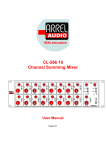
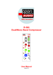
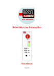
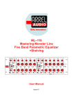
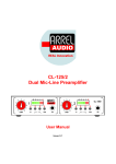
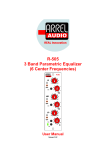
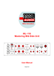
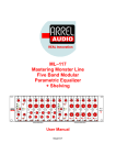
1
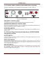
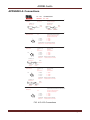
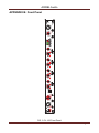
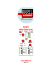
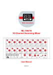
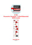
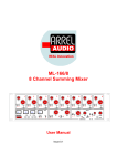
REAL Innovation CL-123 Channel Strip MICRO 4 5 6 3 2 7 2 8 1 AUDIO 10 GAIN LO 2 10 14 REV 60 14 dB 80 2 100 40 30 6 12 KHz 10 9 0 ON 0 6 80 Hz 0 MID 1 2 6 160 25 20 200 Hz 300 6 140 400 10 150 10 14 14 dB 2 500 600 200 800 1000 100 Hz 0 MID 2 2 6 1K 800 700 6 10 10 14 14 dB 1.5K 2 2K 0 HI 6K 2 6 600 4K 5K 500 Hz 10 14 14 dB -6 0 +6 -3 14K 2.5K +3 16K 2K 20K Hz EQ OFF DISPL POST INS POST INS OFF -6 +6 MASTER TRIM LINE 48 V OUT 0 10K 3K 10 -18 -12 8K 4K 6 3K INSERT PHASE SEND User Manual Issue 0.1 RETURN CL-123 ARREL Audio SAFETY INSTRUCTIONS WARNING Always follow the precautions listed below to avoid any possibility of serious injury or even death from electrical shock, shortcircuiting, damages, fire or other hazards. These precautions include, but are not limited to, the following: Do not expose the instrument to liquids and rain. Do not use it near water or in damp or wet conditions, or place containers on it containing liquids. If any liquid seeps turn off the power and unplug the power cord from the AC outlet. Do not put burning items, such as candles, on the unit. A burning item may fall over and cause a fire. This instrument contains no user-serviceable parts. Do not open the instrument or attempt to disassemble or modify the internal circuit. Never insert or remove an electric plug with wet hands. Check the electric plug periodically and remove any dirt or dust which may have accumulated on it. Do not place the power cord near heat sources such as heaters or radiators, and do not excessively bend or otherwise damage the cord, place heavy objects on it, or place it in a position where anyone could walk on, trip over, or roll anything over it. CAUTION Always follow the precautions listed below to avoid any possibility of serious injury or even death from electrical shock, shortcircuiting, damages, fire or other hazards. These precautions include, but are not limited to, the following: Do not connect the instrument to an electrical outlet using a multiple-connector. Doing so can result in lower sound quality, or possibly cause overheating in the outlet itself. When removing the electric plug from the instrument or an outlet, hold the plug itself and not the cord. Pulling by the cord can damage it. Remove the electric plug from the outlet when the instrument is not to be used for extended periods of time, or during electrical storms. Do not place the instrument in an unstable position where it might accidentally fall over. Before moving the instrument, remove all connected cables. When setting up the product, make sure that the AC outlet you are using is easily accessible. If some trouble or malfunction occurs, immediately turn off the power switch and disconnect the plug from the outlet. Even when the power switch is turned off, electricity is still flowing to the product at the minimum level. When you are not using the product for a long time, make sure to unplug the power cord from the wall AC outlet. Use only the stand/rack specified for the instrument. When attaching the stand or rack, use the provided screws only. Failure to do so could cause damage to the internal components or result in the instrument falling over. Information for Users on Collection and Disposal of Old Equipment This special symbol on the products, packaging, and/or accompanying documents means that used electrical and electronic products should not be mixed with general household waste. For proper treatment, recovery and recycling of old products, please take them to applicable collection points, in accordance with your national legislation and the Directives 2002/96/EC. By disposing of these products correctly, you will help to save valuable resources and prevent any potential negative effects on human health and the environment which could otherwise arise from inappropriate waste handling. For more information about collection and recycling of old products, please contact your local municipality, your waste disposal service or the point of sale where you purchased the items. [For business users in the European Union] If you wish to discard electrical and electronic equipment, please contact your dealer or supplier for further information. [Information on Disposal in other Countries outside the European Union] This symbol is only valid in the European Union. If you wish to discard these items, please contact your local authorities or dealer and ask for the correct method of disposal. CL-123 User Manual, Issue 0.1 Page 2 ARREL Audio ARREL Audio Contacts ARREL Audio Via A. Mondadori, 7 00128 Rome – Italy Tel +39 06 506 2017 Fax: +39 06 5062017 Info: [email protected] Web: http://www.arrel-audio.com ARREL Audio Support ARREL Audio is continuously working to the improvement of its systems and related documentation. In any case, we reserve the right to change the specifications without notice but in the respect to the current legislation. Disclaimer: The information contained in this manual has been carefully checked and we believed is accurate at the time of publication. In any case, we do not assume any responsibility for inaccuracies, errors or omissions nor any liability for any loss or damage resulting either directly or indirectly from use of the information contained in this manual. CL-123 User Manual, Issue 0.1 Page 3 ARREL Audio TABLE OF CONTENTS SAFETY INSTRUCTIONS ................................................................................................... 2 Housing................................................................................................................................ 6 CL-123 Front Panel Controls and Operations: Input Stage.................................................. 7 Input Source selection ...................................................................................................... 7 Phantom-Power switch..................................................................................................... 7 Phase switch .................................................................................................................... 7 Gain Control knob ............................................................................................................7 LO-CUT switch .................................................................................................................7 HI-CUT switch .................................................................................................................. 7 CL-123 Front Panel Controls and Operations: EQ stage ................................................. 8 frequency control knob ..................................................................................................... 8 emphasis/de-emphasis control knob ................................................................................ 8 q control switch ................................................................................................................ 8 CL-123 Front Panel Controls and Operations: OUTPUT STAGE and general controls ....... 8 eq off switch ..................................................................................................................... 8 displ post switch ............................................................................................................... 8 ins post switch .................................................................................................................. 8 ins off switch ..................................................................................................................... 9 Level Indicator .................................................................................................................. 9 master trim knob ..............................................................................................................9 send/return input jacks ..................................................................................................... 9 output xlr .......................................................................................................................... 9 APPENDIX A: Connections................................................................................................ 10 APPENDIX B: Front Panel ................................................................................................. 11 APPENDIX C: Back Panel ................................................................................................. 12 APPENDIX E: Measurements............................................................................................ 13 ........................................................................................................................................... 14 ........................................................................................................................................... 15 TECHNICAL SPECIFICATIONS ........................................................................................ 16 CL-123 User Manual, Issue 0.1 Page 4 ARREL Audio INTRODUCTION The ARREL Audio CL- 123 channel strip has been conceived to give to the professional user a unit that combines high reliability, rugged design, audio quality, versatility and ease of use. CL-123 is perfect for recording every kind of music from classic, pop/rock, electronic and in all the situations where maximum sound quality and special attention to dynamic range and signal to noise ratio is needed. The CL-123 technical specification shows that it is the perfect audio system for actual digital recording 24bit/192kHz environments where superior performance is required. CL-123 is based on the use of the latest circuit topologies, characterized by very low distortion, ultra-low noise and very wide frequency response. The ARREL Audio CL-123 channel strip, is composed by a high quality mic-line preamplifier, a four band parametric equalizer, a level metering system and a flexible insert return. The preamplifier architecture is based on two high dynamic range gain stages to avoid any saturation and the best possible linearity. Even if the input stage of the CL-123 could accept input signals up to +24 dBu, a protection circuit limits the input level at +20 dBu in order to prevent any damage. The CL-123 extended input dynamic range avoids the necessity of the input pad and the gain is controlled by a single large knob. The absence of the input pad means better sonic performances. In fact being it an attenuator it deteriorates the sound quality and reduces the signal to noise ratio. The channel strip contains a special circuit that allows the connection of microphones even if the unit is turned on with the Phantom Power activated (in any case we do not recommend this practice in order to protect your microphones). CL-123 also provides a four band fully parametric EQ with High-Cut/Low-Cut filters at fixed cut-off frequencies (80 Hz / 12 kHz) which can be activated by a switch. Each filter stage is completely excluded from the main circuit if not in use. The emphasis/de-emphasis adjustment is based on a special circuit topology that guarantees a very linear and accurate control. The flexibility of the CL-123 channel strip is increased by a level meter (mic-line out or equalizer out measurements) and an insert point (send and return electronically balanced) available both on the front panel and on the back panel. The insert point can be configured either as pre eq. or post eq. The insert jacks on the front panel deselect the outboard connected on the back panel. In this way the user can permanently connect the most used outboard to the insert/return connectors on the back panel and, when a new outboard is required, it can be connected by using the front panel connectors disconnecting automatically the back connected outboard. In this way additional outboards can be easily connected with no access on the back panel. In the CL-123 no compressor is provided. This corresponds to a precise design choice. In fact usually the compressor technology and consequently the compressor sound is a sort of “artistic choice” so ARREL Audio CL-123 give to the user the possibility to connect your preferred compressor as an insert. CL-123 User Manual, Issue 0.1 Page 5 ARREL Audio Differently from other channel strips, the CL-123 is dedicated (due to his absolute sonic level quality) to high professional vocal recordings, classical instruments, high dynamic range instruments such as drums and percussions. ARREL Audio products are designed and manufactured in Italy. Housing The CL-123 has been designed to be compliant with a 1U rack. No specific air conditioning is required for the racks, provided that there is a free flow of air through the rack from front to back and the temperature is maintained in the operating range. Consequently the racks may be stacked. CL-123 User Manual, Issue 0.1 Page 6 ARREL Audio CL-123 Front Panel Controls and Operations: Input Stage INPUT SOURCE SELECTION The CL-123 input stage is based on a differential amplifier so it is “electronically balanced”. If the Line-In 1/4" jack is not inserted on the front panel the mic input is activated, the insertion of the Line In jack disconnects the mic input. Due to its very high dynamic range, the ARREL Audio CL-123 does not require any input PAD switch. Two XLRs for the mic input are available, the first one on the front panel and the second one on the back panel (Fig. 1and Fig. 6). Just one mic input at a time can be used. PHANTOM-POWER SWITCH Select the proper position of the switch to activate the +48 V Phantom Power (red LED on). To deselect the Phantom Power return to the previous position (red LED off) (Fig. 1). The switch is subminiature type (short lever) type in order to avoid accidental operations. PHASE SWITCH Select the proper position of the switch to activate the phase inversion (red LED on). To deselect the Phantom Power return to the previous position (red LED off) (Fig. 1). The switch is of the subminiature type (short lever) in order to avoid accidental operations. MICRO 4 5 6 3 2 7 2 ON 80 Hz 10 GAIN 60 10 10 14 REV 14 dB 80 100 40 30 6 12 KHz 9 0 LO 2 6 8 1 AUDIO 0 140 160 25 20 200 Hz LINE 48 V PHASE Fig. 1 CL-123 Input section GAIN CONTROL KNOB Turn the gain knob in order to select the required amount of gain for either the mic input or the Line input. The maximum gain of the mic input is 66 dB. The gain of the Line input is 30 dB (Fig. 1). LO-CUT SWITCH Normal operation (LO-CUT filter not inserted), switch in down position. LO-CUT filtering activated with the switch in the up position. The filter cut-off frequency is 80 Hz (12 dB / Oct.) (Fig. 1). HI-CUT SWITCH Normal operation (HI-CUT filter not inserted), switch in down position. HI-CUT filtering activated with the switch in the up position. The filter cut-off frequency is 8 KHz (12 dB / Oct.) (Fig. 1). CL-123 User Manual, Issue 0.1 Page 7 ARREL Audio CL-123 FRONT PANEL CONTROLS AND OPERATIONS: EQ STAGE The same considerations can be applied to the three bands: LO, MID1, MID2, HI. MICRO 5 4 6 3 2 7 2 ON 80 Hz 10 GAIN 12 KHz 10 14 REV 60 80 100 40 30 6 10 9 0 LO 2 6 8 1 AUDIO 0 14 dB 140 160 25 20 200 Hz LINE 48 V PHASE Fig. 2 CL-123 EQ section FREQUENCY CONTROL KNOB The frequency band can be easily tuned by rotating the frequency Hz knob. EMPHASIS/DE-EMPHASIS CONTROL KNOB Rotate the emphasis/de-emphasis control knob (dB knob) (center detent potentiometer) to change the frequency content in a range of ± 14 dB. Q CONTROL SWITCH Turn the toggle switch to change the Q parameter. Three positions are available: narrow, medium, wide. CL-123 Front Panel Controls and Operations: OUTPUT STAGE and general controls EQ OFF SWITCH Push the button to turn off the equalizer (red LED on). Press again to switch to turn on the equalizer (red LED off) (Fig. 3). DISPL POST SWITCH Push the button to select DISPLAY POST (red LED on). In this position the level meter is connected at the output of the equalizer. Press again to display the level at the out of the mic-line stage (red LED off) (Fig. 3). INS POST SWITCH Push the button to select insert post (red LED on). In this position the insert point is after the equalization stage. Press again to switch to have the insert point before the equalization stage (red LED off) (Fig. 3). CL-123 User Manual, Issue 0.1 Page 8 ARREL Audio -18 -12 -6 0 +6 OUT 0 -3 EQ OFF DISPL POST INS POST +3 -6 +6 MASTER TRIM INS OFF CL-123 INSERT SEND RETURN Fig. 3 CL-123 output section INS OFF SWITCH Push the button to turn off the insert point (red LED on). Press again to switch turn on the insert point (red LED off) (Fig. 3). LEVEL INDICATOR The output level Indicator is based on a 10-LED Bargraph (7 x green LEDs and 3 x red LEDs) with measurement range +6/-21 dBu, The resolution in 1.5 dB per step. The input signal to the level meter can be selected by the DISPL POST SWITCH (Fig. 3). The level measurement is not affected by MASTER TRIM control. MASTER TRIM KNOB Rotate the master trim knob to change the output level in the range of ± 6 dB (center detent potentiometer). The Master Trim gain does not affect the level indicator (Fig. 3). SEND/RETURN INPUT JACKS The insert and return connectors are available on the front panel (1/4 “jack) (Fig. 3) and on the back panel (XLR connectors) (Fig. 6). The front panel insert jack deselects the back panel insert connector. In this way the user can permanently connect the most used outboard to the insert return connectors on the back and, when a new outboard is required, it can be connected by using the front panel connectors. Automatically the back connected outboard will be disconnected. In this way additional outboards can be easily connected without the access on the back panel. IMPORTANT NOTE The CL-123 can be used as a separate mic-line preamplifier and equalizer. MIC-LINE PREAMP: The send out (after the mic-line stage) is used as the output of the mic-line preamplifier (electronically balanced, out level +4 dBu). EQUALIZER: The return is used as the preamplifier line input (electronically balanced, out level +4 dBu). OUTPUT XLR The output signal is available on two XLRs: the first one on the front panel (Fig. 3), the second one on the back panel (Fig. 6). The two connectors can be used together without problems. CL-123 User Manual, Issue 0.1 Page 9 ARREL Audio APPENDIX A: Connections CL - 123 WIRING AUDIO CONNESSIONI CL - 123 INGRESSO LINEA Jack Mono 6,35 Puo' essere usato anche Jack stereo LINE INPUT Mono Jack 1/4" Stero Jacks can be used Jack Mono 6,35 Mono Jack 1/4" Jack Stereo 6,35 Stereo Jack 1/4" FASE FASE PHASE PHASE MASSA MASSA MASSA GROUND GROUND GROUND INGRESSO MICROFONO MICROPHONE INPUT XLR XLR Posteriore - duplicato sul pannello anteriore E' possibile usare uno solo dei 2 ingressi On the back - doubled on front panel It is possible to use one input only 3 1 2 1 = Massa 1 = Ground 2 = FASE + 2 = PHASE + 3 = FASE - 3 = PHASE - Solo linea bilanciata - Non connettere linee sbilanciate Balanced line only - dont' connect unbalancedc cables USCITA INSERZIONE INSERT SEND XLR Jack Stereo 6,35 Posteriore Sul pannello frontale XLR Stereo Jack 1/4" On the back On the front panel 3 XLR 1 2 1 = Massa 1 = Ground 2 = FASE + 2 = PHASE + 3 = FASE - 3 = PHASE - Linea bilanciata - Possibile connettere linee sbilanciate Balanced line - Unbalanced cables can be connected Jack Stereo 6,35 Stereo Jack 1/4" FASE + PHASE + MASSA FASE - GROUND PHASE - RITORNO INSERZIONE INSERT RETURN XLR Jack Stereo 6,35 Posteriore Sul pannello frontale XLR Stereo Jack 1/4" On the back On the front panel 3 XLR 1 2 1 = Massa 1 = Ground 2 = FASE + 2 = PHASE + 3 = FASE - 3 = PHASE - Linea bilanciata - Possibile connettere linee sbilanciate Balanced line - Unbalanced cables can be connected Jack Stereo 6,35 Stereo Jack 1/4" FASE + PHASE + MASSA GROUND FASE PHASE - USCITA MASTER XLR Posteriore - duplicato sul pannello anteriore E' possibile usare contemporaneamente tutte e due le uscite XLR On the back - doubled on front panel It is possible to use both output MAIN OUTPUT 3 1 2 1 = Massa 1 = Ground 2 = FASE + 2 = PHASE + 3 = FASE - 3 = PHASE - Linea bilanciata - Possibile connettere linee sbilanciate Balanced line - Unbalanced cables can be connected FIG. 4 CL-123 Connections CL-123 User Manual, Issue 0.1 Page 10 AUDIO ON 48 V CL-123 User Manual, Issue 0.1 LINE MICRO 3 1 2 0 4 GAIN 5 10 6 8 REV PHASE 9 7 80 Hz 12 KHz 10 6 14 2 dB 0 14 2 6 10 25 60 20 40 30 LO Hz 80 200 160 140 100 10 6 14 2 dB 0 14 2 6 100 10 150 200 300 MID 1 Hz 400 1000 800 500 600 10 6 14 2 dB 0 14 2 6 10 1K 500 600 800 700 MID 2 Hz 1.5K 5K 3K 4K 2K 10 6 14 2 dB 0 14 2 6 10 4K 6K 2K 2.5K 3K HI Hz 8K 20K 16K 14K 10K EQ OFF DISPL POST -18 -12 -6 INS POST 0 +6 INS OFF 0 +3 RETURN INSERT -6 +6 MASTER TRIM SEND -3 OUT CL-123 ARREL Audio APPENDIX B: Front Panel FIG. 5 CL-123 Front Panel Page 11 CL-123 User Manual, Issue 0.1 FUSE WARNING DESIGNED AND MANUFACTURED IN ITALY TO RAIN OR MOISTURE AUDIO LY RED FUSE 0.5 A SHOCK DO NOT EXPOSE THIS EQUIPMENT DO NOT OPEN TO REDUCE THE RISK OF FIRE OR EJECTRIC RISK OF ELECTRIC SHOCK CAUTION CHANNEL STRIP CL - 123 AUDIO 3 = PHASE - 2 = PHASE + 1 = GROUND OUTPUT RETURN INSERT SEND INPUT ARREL Audio APPENDIX C: Back Panel FIG. 6 CL-123 Back Panel Page 12 ARREL Audio APPENDIX E: Measurements Signal Path1 : Frequency Response Measured 1 25/12/2014 17:54:09 CL-123-FREQUENCY RESPONSE (25/12/2014 17:54:09) FIG. 8 Frequency Response Signal Path1 : Frequency Response Measured 1 25/12/2014 17:53:13 CL-123-HI-LO (25/12/2014 17:53:13) FIG. 8 Frequency Response LPF and HPF CL-123 User Manual, Issue 0.1 Page 13 ARREL Audio FIG. 8 Equalizer LO Band FIG. 8 Equalizer MID 1 Band CL-123 User Manual, Issue 0.1 Page 14 ARREL Audio FIG. 8 Equalizer MID 2 Band FIG. 8 Equalizer HI Band CL-123 User Manual, Issue 0.1 Page 15 ARREL Audio TECHNICAL SPECIFICATIONS Number of Channels: 1 Power Supply Linear Regulator ± 18 VDC (Balanced C-Core Transformer) Operating Voltage 220V 50 Hz, (110V 60 Hz version available) Power Consumption 20 W Microphone Input Electronically balanced Microphone Gain 66 dB range with rotary knob control Theoretical max input level +24 dBu (internally limited to +20 dBu) Line Input Unbalanced, Impedance 22 KΩ, (this input can be also used as EQ input) Line Gain 30 dB range with rotary knob control Level 0/-30 dBu. Max +23 dBu Bandwidth 5 - 200.000 Hz -1dB, perfect square wave up to 20 KHz Distortion + Noise <0.003% ( typical 0.001%) Low Cut Filter 80 Hz, 12 dB / Oct High Cut Filter 8 KHz, 12 dB / Oct Parametric EQ 4 band with overlapping frequencies: 20 - 200 Hz, 100 - 1.0 Hz, 500 - 5.0 Hz, 2.0 - 20.000 Hz Three Q settings – narrow, normal, wide ± 14 dB gain range for emphasis/de-emphasis Output Electronically Balanced Level +4 dBu. Max +28 dBu, external load > 600 Ω Insert send Electronically Balanced, lev +4 dBu, max. +28 dBu, external load > 600 Ω Insert return Electronically Balanced, lev +4 dBu, max. +23 dBu, Input impedance > 10 KΩ Front Panel Controls Gain rotary knobs (min gain and level gain), 48V Phantom Power switch Lo-Cut and Hi-Cut switches, Phase Reverse switch “3-way Q settings” toggle switch (each band), ± 14 dB range for boost/cut Central Frequency rotary knob, 4x push-button for EQ off Pre/Post EQ, Display mode: Pre/Post Insert, Insert off Output level rotary knob Front Panel Connectors 1/4” TRS jack for kine input Balanced XLR female for microphone input 2x 1/4” TRS jacks for insert connections (Send/Return) Balanced XLR male output Front Panel Indicators Level Indicator 10-LED Bargraph (7x green, 3x red). 1.5 dB step, 4x red LEDs (48V Phantom Power, Hi-Cut, Lo-Cut, Phase). Balanced XLR female input Rear Panel Input Connectors Balanced XLR male output Balanced XLR female/male for Insert (Send/Return) AC mains IEC C13 16 A connector, AC mains cord with IEC Schuko 16A Construction 19" 1U rack mount metal box Dimensions W 483 mm / 19”, H 44.45 mm/1.75” (1 U), D 225 mm / 8.86” Weight 2.5 kg CL-123 User Manual, Issue 0.1 Page 16