1
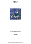
ABSOLUTE ROTARY ENCODER
PROFIBUS-DP
®
PROCESS FIELD BUS
Main Features
- Compact and heavy-duty industrial model
- Certified: By Profibus Trade Org., CE
- Interface: Profibus-DP
- DPV2-Functionality
- Housing: 58 mm ∅
- Full or hollow shaft: 6 or 10 mm ∅ / 15 mm ∅
- Max. 65,536 steps per revolution (16 Bit)
- Max. 16,384 revolutions (14 Bit)
- Code:
Binary
Programmable Parameters
- Direction of rotation (complement)
- Resolution per revolution
- Total resolution
- Preset value
- Output of velocity
- Time base for velocity
- Software Limit Switches
- Parameters for isochronous mode
Mechanical Structure
- Flange and housing of Aluminum
- Shaft of stainless steel
- Precision ball bearings with sealing or cover rings
- Code disc made of unbreakable and durable
plastic
Electrical Features
- Status indication with two LEDs in the connection
cap
- 400 million write cycles
- Temperature insensitive IR-opto-receiver-ASIC
with integrated signal conditioning
- Polarity inversion protection
- Over-voltage-peak protection
FRABA Inc.
14 Washington Rd., Building 6, Princeton Junction, NJ 08550, Phone 877-873-7222, Fax 866-329-3722
www.posital.com, [email protected]
ABSOLUTE ROTARY ENCODER
PROFIBUS-DP
Technical Data
Electrical Data
Interface
Line-driver according to RS 485,
galvanically isolated by opto-couplers
Transmission rate
Max. 12 MBaud
Device addressing
Adjustable by rotary switches in connection cap
Supply voltage
10 - 30 V DC (absolute limits) *
Current consumption
Max. 230 mA with 10 V DC, max. 100 mA with 24 V DC
Power consumption
Max. 2.5 Watts
Step frequency LSB
800 kHz
Accuracy of division
± ½ LSB (12 bit), ± 2 LSB (16 bit)
EMC
Emitted interference: EN 61000-6-4
Noise immunity:
Electrical lifetime
EN 61000-6-2
5
> 10 h
* Supply voltage according to EN 50 178 (safety extra low voltage)
Mechanical Data
Housing
Aluminum, optional stainless steel
Lifetime
Dependent on shaft version and shaft loading – refer to table
Max. shaft loading
Axial 40 N, radial 110 N
Inertia of rotor
≤ 30 gcm2
Friction torque
≤ 3 Ncm (without shaft sealing)
RPM (continuous operation)
Singleturn:
max. 12,000 RPM
Multiturn:
max. 6,000 RPM
Shock (EN 60068-2-27)
≤ 100 g (halfsine, 6 ms)
Permanent shock (EN 60028-2-29)
≤ 10 g (halfsine, 16 ms)
Vibration (EN 60068-2-6)
≤ 10 g (10 Hz ... 2,000 Hz)
Weight (standard version)
Singleturn:
≈ 550 g
Multiturn:
≈ 600 g
Singleturn:
≈ 1,100 g
Multiturn:
≈ 1,200 g
Weight (stainless steel version)
Flange
Clamp (C)
Hollow shaft (B)
Shaft diameter
6 mm
10 mm
10 mm
15 mm
Shaft length
10 mm
20mm
20 mm
-
-
-
-
15 mm / 30 mm
hollow shaft depth min. / max.
Version 03/04
Synchro (S)
USE Info OCD DP
Page 2
ABSOLUTE ROTARY ENCODER
PROFIBUS-DP
Minimum (mechanical) lifetime
Lifetime in 108 revolutions with Fa / Fr
Flange
40 N / 60 N
40 N / 80 N
40 N / 110 N
C10 (Clamp flange 10 x 20)
247
104
40
S10 (Synchro flange 10 x 20)
262
110
42
S6 (Synchro flange 6 x 10) without shaft sealing
822
347
133
S6 (Synchro flange 6 x 10) with shaft sealing: max. 20 N axial, 80 N radial
Environmental Conditions
Operating temperature
- 40 .. + 185 °F
Storage temperature
- 40 .. + 185 °F
Humidity
98 % (without liquid state)
Protection class (EN 60529)
Casing side: IP 65
Shaft side: IP 64 (optional with shaft sealing: IP66)
Version 03/04
USE Info OCD DP
Page 3
ABSOLUTE ROT ARY ENCODER
PROFIBUS-DP
Interface
Installation
The rotary encoder is connected by two or three
cables, depending on whether the power supply is
integrated into the bus cable or connected separately. If the power supply is integrated into the bus
cable one of the cable glands can be fitted with a
plug. The cable glands are suitable for cable diameters from 6.5 up to 9 mm.
Termination resistors are integrated in the connection cap. These must be switched on if the encoder
is connected at the end or the beginning of the bus.
R
R
ON
ON
device X
last device
R
Connecting the data line and the power supply
ON
B
A
+
B
A
+
+
B
A
+
Clamp
Description
B (left)
Bus line B (Bus in)
456
4 56
B
A
A (left)
Bus line A (Bus in)
x10
x1
-
0V
+
10 – 30 V
B (right)
Bus line B (Bus out)
A (right)
Bus line A (Bus out)
-
0V
901
78
23
23
78
901
+
10 – 30 V
The power supply has to be connected once (no
matter which clamps). If the terminating resistor is
The Profibus-DP device address is set by userfriendly rotary switches in the connection cap. Allowed addresses are between 1 and 99, each can
only be used once. The connection cap can easily
be opened for installation by removing the two cap
screws.
Version 03/04
switched on the outgoing bus lines are
disconnected.
A GSD-file is necessary for installing the encoder.
The disc with the GSD-file and the detailed user
manual can be ordered from FRABA or downloaded
from our homepage (www.posital.de).
The connection cap is provided with two LEDs on
the backside, which optically represent the device
status. This can be very useful for installing and
setting-up the encoder.
USE Info OCD DP
Page 4
ABSOLUTE ROTARY ENCODER
PROFIBUS-DP
Programmable Parameters
The Profibus-DP interface supports CLASS 1 and
CLASS 2 functionality according to the encoder
profile*. In addition to these functions the GSD-file
supports further features, for example software limit
switches. Further more, the following encoder parameters can be programmed directly via the
Profibus-DP network without any extra device:
Counting Direction
This parameter counting direction defines whether the output code
increases or decreases when the shaft rotates clockwise.
Resolution per Revolution
The parameter ‘resolution per revolution’ is used to program the desired number of steps per revolution. Each value between 1 and the
physical resolution per revolution can be programmed.
Total Resolution
This parameter is used to program the desired number of measuring
units over the total measuring range. This value may not exceed the
total physical resolution of the absolute rotary encoder.
Preset Value
The preset value is the desired position value, which should be
reached at a certain physical position of the axis. The position value is
set to the desired process value by the parameter preset.
Velocity
The implemented software can additionally deliver the current velocity.
This value is transmitted in binary code, 16 Bit, in addition to the process value.
It is possible to choose between four different units: steps per 10 ms,
per 100 ms, per 1000 ms and revolutions per minute.
Software limit switches function
Two software limit switches can be set. If the position value falls below
the lower or exceeds the higher limit switch, a status bit in the process
value is set.
Teach-in (Online parameterization)
A special mode is available for commissioning phase of the device.
This makes it possible to change parameters while the encoder is in
data exchange mode.
For continuous operation another mode is available in which the parameters are protected against unintentional changes.
* The Profibus-DP profile for encoder can be
ordered from
Profibus Nutzerorganisation e.V.
Haid und Neu-Str. 7,
D-76131 Karlsruhe, Germany
with order-No. 3.062.
Version 03/04
E Info OCD DP
Page 5
ABSOLUTE ROT ARY ENCODER
PROFIBUS-DP
Mechanical Drawings
Synchro flange (S)
Available in two versions
Synchro flange
d / mm
l / mm
Version S06
6f6
10
Version S10
10h8
20
Single-Turn=82, Multi-Turn=92
30
3xM4x6
Ø42
Ø60
~32
l
63,5
Ø59 (Ø61)*
d
ø58
ø50 f7
0°
12
3x
23
3
3
4
* Edelstahl / Stainless steel
15
Ø6,5-9
20
20
Schlüsselweite, wrench size=17
Clamp flange (C)
Single-Turn=82, Multi-Turn=92
30
30
3xM4x6
0°
12
3x
3xM3x6
15°
63,5
Ø60
23
Ø4
8
Ø59 (Ø61)*
1
Ø36 f7
Ø10 h8
Ø53
Ø58
3 x1 2
0°
10
18
~27
3
3
* Edelstahl / Stainless steel
15
Ø6,5-9
20
20
Schlüsselweite, wrench size=17
Version 03/04
USE Info OCD DP
Page 6
ABSOLUTE ROTARY ENCODER
PROFIBUS-DP
Hollow shaft (B)
72
Ø63
Single-Turn=100 , Multi-Turn=112
3,3
20
Ø60
63,5
Ø15 F7
23
20°
Ø59 (Ø61)*
1,3
~32
Anlagekante
an Momentenstütze
(lay-on edge
torque support)
Ø3,2
* Edelstahl / Stainless steel
Max. W ** = 30
Min. W ** = 15
Ø6,5-9
15
20
** Welleneinstecktiefe (hollow shaft depth)
20
Schlüsselweite, wrench size=17
Mounting instructions
The clamp ring may only be tightened if the shaft of
the driving element is in the hollow shaft.
The diameter of the hollow shaft can be reduced to
12mm, 10 mm or 8 mm by using an adapter (this
reducing adapter can be pushed into the hollow
shaft).
Version 03/04
Allowed shaft movements of the drive element are
listed in the table.
Axial
Radial
Static
± 0.3 mm
± 0.5 mm
Dynamic
± 0.1 mm
± 0.2 mm
USE Info OCD DP
Page 7
ABSOLUTE ROT ARY ENCODER
PROFIBUS-DP
Versions / Ordering description
Description
Type Key
Optocode
Interface
OCDProfibus
Version
Code
Revolutions (Bits)
B1
Binary
Singleturn
Multiturn (4096 revolutions)
Steps per revolution
(Bits)
Flange
Shaft diameter
Mechanical options
Connection
DP
DP
B1
Multiturn (16384 revolutions)
4096
8192
65536
Clamp flange
Synchro flange
Hollow shaft
10 mm
B-
__
__-
_
__
_-
0CC
B
00
12
14
12
13
16
06 mm
15 mm (hollow shaft)
Without
Shaft sealing (IP66)
Stainless steel version
Customized
Connection Cap
Has to be ordered separately – see accessories
C
S
B
10
06
15
0
S
V
C
0CC
Standard = bold, further models on request
Version 03/04
USE Info OCD DP
Page 8
ABSOLUTE ROTARY ENCODER
PROFIBUS-DP
Accessories and Documentation
Description
Connection cap
Type
T-coupling-functionality
setting Standard
with
integrated
address
AH 58-B1DP-3PG
Stainless steel configuration
AH 58-B1DP-3PG-VA
Connection cap “2M20”
- special version -
Same function as standard cap but only two cable
glands for cable diameters from 9 up to 13 mm
AH 58-B1DP-2M20
Shaft coupling **
Drilling: 10 mm
GS 10
Drilling: 6 mm
GS 06
Disc with GSD-file *
Must be ordered once encoder is used for the first
time
DK-AWC-DP
Clamp disc **
4 pcs. / AWC
SP 15
Clamp ring **
2 pcs. / AWC
SP H
Reducing adapter ***
15 mm to 12 mm
RR12
Reducing adapter ***
15 mm to 10 mm
RR10
Reducing adapter ***
15 mm to 8 mm
RR8
User manual *
Installation / configuration manual for Profibus, English
UMUSE-B1DP
User manual *
Installation / configuration manual for Profibus, German UMD-B1DP
*
These can be downloaded free of charge from our homepage www.posital.de.
** not for hollow shaft
*** only for hollow shaft
We do not assume responsibility for technical inaccuracies or omissions. Specifications are subject to
change without notice.
Version 03/04
USE Info OCD DP
Page 9