1
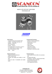
ABSOLUTE ROTARY ENCO DER PROFINET IO Main Features - Compact and heavy duty industrial model - Interface: Profinet IO - Certified by PROFIBUS Nutzerorganisatiion e.V. - Housing: 58 mm - Full shaft: 6 or 10 mm / hollow shaft15 mm - Resolution: max. 30 Bit = 1,073,741,824 steps over 16,384 revolutions - Code: Binary Programmable Parameters - Resolution - Total resolution - Preset value - Direction of rotation (complement) - Velocity - IP-Address Mechanical Structure - Flange and housing, Aluminum and Brass respectively - Stainless steel shaft - Precision ball bearings with sealing rings - Code disc made of durable and unbreakable plastic - Robust electrical connection with M12-connector Electrical Features - Integrated IRT-compatible switch - Status indication with six LEDs - Temperature insensitive IR-Opto-receiver-ASIC - Polarity inversion protection - Over-voltage-peak protection SCANCON Encoders a/s Tranevang 1 3450 Alleroed Denmark Tlf: +45 48172702 fax: +45 48172284 www.scancon.dk [email protected] ABSOLUTE ROT ARY ENCO DER PROFINET IO Technical Data Electrical Data Supply voltage 10 - 30 V DC (absolute limits) Power consumption max. 4 Watt EMC Emitted interference: EN 61000-6-4 Noise immunity: EN 61326-1 Bus connection Profinet IO Transmission rate 100 MBit Accuracy of division ½ LSB (up to 12 Bit), ± 2 LSB (up to 16 Bit) Step frequency LSB max. 800kHz (valid code) Cycle time 1 ms (IRT), 10 ms (RT) Internal cycle time ~ 500 µs Electrical lifetime > 105 h Device addressing Programmable IP-Address by the master Mechanical Data Housing Aluminum, optional stainless steel Lifetime Dependent on shaft version and shaft loading – refer to table Max. shaft load Axial 40 N, radial 110 N Inertia of rotor 30 gcm2 Friction torque 3 Ncm (without shaft sealing) RPM (continuous operation) max. 12,000 RPM Shock (EN 60068-2-27) 100 g (halfsine, 11 ms) Permanent shock (EN 60028-2-29) 10 g (halfsine, 16 ms) Vibration (EN 60068-2-6) 10 g (10 Hz ... 1,000 Hz) Weight (standard version) Singleturn: 500 g Multiturn: 700 g Flange Synchro (S) Clamp (C) Hollow shaft (B) Shaft diameter 6 mm 10 mm 10 mm 15 mm Shaft length 10 mm 20mm 20 mm - - - - 15 mm / 30 mm hollow shaft depth min. / max. Page 2 E Info SAG EI Version: 16.10.2010 ABSOLUTE ROT ARY ENCO DER PROFINET IO Minimum (mechanical) lifetime Lifetime in 108 revolutions with Fa / Fr Flange 40 N / 60 N 40 N / 80 N 40 N / 110 N C10 (Clamp flange 10 x 20) 247 104 40 S10 (Synchro flange 10 x 20) 262 110 42 S6 (Synchro flange 6 x 10) without shaft sealing 822 347 133 S6 (Synchro flange 6 x 10) with shaft sealing: max. 20 N axial, 80 N radial Environmental Conditions Operating temperature - 40 .. + 85°C Storage temperature - 40 .. + 85 °C Humidity 98 % (without liquid state) Protection class (EN 60529) Casing side: IP 67 Shaft side: IP 64 (optional with shaft sealing: IP67) Conformity UL International - For use in NFPA 79 Applications only - Adapters providing field wiring means are available from the manufacturer. Refer to manufacturers information. CE Version 16.10.2010 E Info SAG EI Page 3 ABSOLUTE ROT ARY ENCO DER PROFINET IO Technology PROFINET is an Industrial Ethernet standard merging plant automation with other enterprise IT resources. It provides comparable functionality to PROFIBUS with techniques used by engineering, IT, and management personnel. as description language for device profiles (GSDML files). For further information about the function principle or the setup of a PROFINET network please, refer to the manual on www.scancon.dk or http://www.profibus.com/pn. Established IT standards are employed as basis of communication: TCP, UDP, IP. XML is used PROFINET offers scalable communication for different applications in industrial automation: PROFINET NRT (non real time) is suited for non-time-critical process automation with clock rates of roughly 100 msec. PROFINET RT (real time) offers a communication channel with optimized performance (10 msec clock rate) for most factory automation tasks PROFINET IRT (isochronous real time) employs special communication After completion of the engineering the installer loads the data for the expansion into the IO controller (PLC) and the IO controller assumes data exchange with the IO device. hardware to enable clock rates of under 1 msec and a jitter precision of less than 1 µsec. This channel is mainly of use for motion control applications. can be exchanged acyclically during engineering of the IO device or by the use of PLC programming blocks. An IO device is addressed within PROFINET (and also possibly by external IT components) through its IP address. Data can be exchanged from the IO controller to the IO device (and vice versa) cyclically (for process data). Apart from this, parameter data PROFINET IO uses a view of distributed I/O similar to PROFIBUS DP. IO controllers (e.g. PLCs) run an automation program, IO devices (e.g. absolute encoders) are remotely assigned field devices, and IO supervisors (e.g. programming devices) are used for commissioning and diagnostics. The engineering of PROFINET IO is done similar to PROFIBUS. The field buses (i.e. Ethernet topologies) are assigned to control systems during configuration. The IO device is configured in the actual system based on the contents of its GSDML file. Page 4 E Info SAG EI Version: 16.10.2010 ABSOLUTE ROT ARY ENCO DER PROFINET IO Pinning Connector Ethernet Connector power supply 4 pin female, D-coded 4 pin male, A-coded Pin Number Signal Pin Number Signal 1 Tx + 1 US (10 - 30 V DC) 2 Rx + 2 N.C. 3 Tx - 3 GND (0V) 4 Rx - 4 N.C. Sketch on encoder view 3 4 4 3 5 2 1 1 2 Diagnostic LED Color Description for LED = on Active1 Yellow Incoming and outgoing traffic for port 1 Link1* Green Link to another Ethernet component for port 1 Active2 Yellow Incoming and outgoing traffic for port 2 Link2* Green Link to another Ethernet component for port 2 Stat1 Green Status 1, details in the user manual Stat2 Red Status 2, details in the user manual * Flashes with 2Hz if engineering identification call is activated and link connection is available Version 16.10.2010 E Info SAG EI Page 5 ABSOLUTE ROT ARY ENCO DER PROFINET IO Programmable Parameters The Profinet IO interface supports CLASS 3 and CLASS 4 functionality according to the encoder functions the GSDML-file supports further features. Further more, the following encoder profile V4 (PNO No. 3.162). Class 4 supports the IRT functionality for isochronous communication for high performance. In addition to these parameters can be programmed directly via the Profinet IO network without any extra device: Counting Direction This parameter counting direction defines whether the output code increases or decreases when the shaft rotates clockwise. Resolution per Revolution The parameter ‘resolution per revolution’ is used to program the desired number of steps per revolution. Each value between 1 and the physical resolution per revolution can be programmed. Total Resolution This parameter is used to program the desired number of measuring units over the total measuring range. This value may not exceed the total physical resolution of the absolute rotary encoder. Preset Value The preset value is the desired position value, which should be reached at a certain physical position of the axis. The position value is set to the desired process value by the parameter preset. Velocity The implemented software can additionally deliver the current velocity. This value is transmitted in binary code, in addition to the process value. It is possible to choose between four different units: steps per 10 ms, per 100 ms, per 1000 ms and revolutions per minute. Details are available in the user manual. These can be downloaded free of charge from our homepage: www.scancon.dk Additional features Integrated Boot loader for customer firmware upgrades Round axis (Endless shaft) Engineering identification call Neighboring detection Different filters for velocity Page 6 E Info SAG EI Version: 16.10.2010 ABSOLUTE ROT ARY ENCO DER PROFINET IO Mechanical Drawings Synchro Flange (S) available in 2 versions Synchro flange d / mm l / mm Version S06 6f6 10 Version S10 10h8 20 Clamp Flange (F) Version 16.10.2010 E Info SAG EI Page 7 ABSOLUTE ROT ARY ENCO DER PROFINET IO Hollow shaft (B) Mounting instructions The clamp ring should only be tightened after the shaft of the driving element was inserted into the hollow shaft. The diameter of the hollow shaft can be reduced to 12 mm, 10 mm or 8 mm by using an adapter (this reducing adapter can be pushed into the hollow shaft). Page 8 Maximum radial and axial misalignment of the drive shaft: axial radial static ± 0.3 mm ± 0.5 mm dynamic ± 0.1 mm ± 0.2 mm E Info SAG EI Version: 16.10.2010 ABSOLUTE ROT ARY ENCO DER PROFINET IO Models/Ordering Description Description Type Key Optocode Interface Version Code Revolutions (Bits) SAGProfinet IRT+RT Steps per revolution Flange (Bits) / Shaft diameter EI EI A1 Connection __ __- ___ _ - PRM A1 Binary Singleturn Multiturn (4,096 revolutions) Multiturn (16,384 revolutions) 8,192 65,536 Clamp flange, full shaft: Synchro flange, full shaft: Blind hollow shaft, hollow shaft : Mechanical options B- B 00 12 14 13 16 Ø 10 mm Ø 6 mm Ø 10 mm Ø 15 mm Without Shaft sealing (IP67) Customized M12 connector C10 S06 S10 B15 0 S C PRM Standard = bold, further models on request Version 16.10.2010 E Info SAG EI Page 9 ABSOLUTE ROT ARY ENCO DER PROFINET IO Accessories and Documentation Description Type Male cable connector M12, 4 pin, D-Coded PAM4 Female cable connector M12, 5 pin, A-Coded PAM5 Connecting cable Ethernet PAM4/RJ45 Straight 5m 10003912 Connecting cable PAM5 2m Shielded 10001978 Coupling ** Drilling: Ø 10 mm GS 10 Drilling: Ø 6 mm GS 06 Clamp disc ** Set = 4 pcs. SP 15 Clamp half-ring ** Set = 2 pcs. SP H Reducing adapter *** 15 mm to 14 mm RR14 15 mm to 12 mm RR12 15 mm to 11 mm RR11 15 mm to 10 mm RR10 15 mm to 8 mm RR8 User manual * Installation / configuration manual, English UME-SAG-EI GSDML file * * These can be downloaded free of charge from our homepage: www.scancon.dk ** Usable only for hollow shaft We do not assume responsibility for technical inaccuracies or omissions. Specifications are subject to change without notice. Page 10 E Info SAG EI Version: 16.10.2010