1
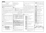
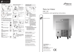
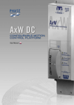
TECHNICAL SPECIFICATIONS
Read this document carefully before using this device. The guarantee will be expired by device
demages if you don't attend to the directions in the user manual. Also we don't accept any
compensations for personal injury, material damage or capital disadvantages.
°F
C1
ELECTRICAL CHARACTERISTICS
A1
°C
F
SET
CAL
OFF.
* Upper and lower setpoint limits can be adjusted.
* Temperature unit can be selected as °C or °F.
ET2412
Supply
Power Consumption
Wiring
Line Resistance
Data Retention
230V AC +%10 -%20, 50/60Hz or 12/24V AC/DC %10
Max. 3VA
Power connector : 2.5mm² screw-terminal, Signal connector : 1,5mm² screw-terminal conenction.
Max. 100ohm
EEPROM (Min. 10 years)
EMC
Safety Requirements
EN 61326-1: 2013 (Performance criterion B is satisfied for EN 61000-4-3)
EN 61010-1: 2012 (Pollution degree 2, overvoltage category II)
Indicator
4 digits, 12.5mm, 7 segment red LED
C1 Output
A1 Output
Life Expectancy for Relay
250V AC, 8A (for resistive load), NO and NC control output.
250V AC, 8A (for resistive load), NO control output.
Control Type
Control Algorithm
A/D Converter
Hysteresis
Single-setpoint and alarm control.
Housing Type
Dimensions
Weight
Enclosure Materials
Suitable for flush-panel mounting according to DIN 43 700.
W77xH35xD61mm
Approx. 215g (After packing)
Self extinguishing plastics
OUTPUT
2 - Relay Current Selection
08.....8A Relay Output
1 - Supply Voltage
230......230V AC
024........24V AC/DC
012........12V AC/DC
SM........7-24VAC/9-30VDC
2
Max. humidity 80% for temperatures up to 31°C decreasing linearly to 50% relative humidity at 40°C.
According to EN60529; Front panel: IP65 Rear panel : IP20
Max. 2000m
Do not use the device in locations subject to corrosive and flammable gasses.
* 77 x 35mm sized.
* Single NTC sensor input.
* Zero point input shift.
* Selectable heating or cooling control for C1 relay output.
* A1 Relay output for alarm control.
* Selectable independent, deviation and band alarm types.
* In the case of sensor failure, relay state can be set to ON or
1
Accuracy
± 1% (for full scale) ± 1 Digit
ENVIRONMENTAL CONDITIONS
Relative Humidity
Protection Class
Height
Thank you for choosing CAL ET2412 ON/OFF Heat Controller.
-
EN 60751
NTC Sensor Resistance
Ambient/Storage temperature 0 ... +50 / °C -25... +70 °C(without icing)
CAL ET2412 ON/OFF HEAT CONTROLLER
Order Code : ET2412 -
INPUT
Scale Range
-60.0...150.0 °C -76.0...302.0°F
Input Type
30.000.000 Switching for no-load operation; 300.000 switching for 8A resistive load at 250VAC.
CONTROL
12 bit resolution, 100ms sampling time.
Adjustable between 0.1 and 20.0°C/F.
HOUSING
CONNECTION DIAGRAM
CAL ET2412 is intended for installation within control panels. Make sure that the device is used only for intended
purpose. The shielding must be grounded on the instrument side. During an installation, all of the cables that are
connected to the device must be free of electrical power. The device must be protected against inadmissible
humidity, vibrations, severe soiling. Make sure that the operation temperature is not exceeded.
All input and output lines that are not connected to the supply network must be laid out as shielded and twisted cables.
These cables should not be close to the power cables or components. The installation and electrical connections must
be carried out by a qualified staff and must be according to the relevant locally applicable regulations.
NTC
A1
250V AC 8A
RESISTIVE LOAD
24V AC/DC ±10%
50/60Hz 5VA
NTC
C1
230V AC +10% -20%
50/60Hz 5VA
A1
A1
°C
NTC
C1
CAL
4
5
6
7
8
9
10
11 12
Neutral
www.west-cs.com
|
8
9
10
Switch
ET2412
11 12
Connection
Cable
2
Note:
230V AC
Supply
Fuse should
be connected Cable size: 1,5mm²
WEST Control Solutions
The Hyde Business Park
Brighton East Sussex
BN2 4JU United Kingdom
Tel : +44 (0) 1273 606271
Fax : +44 (0) 1273 609990
7
1) Mains supply cords shall meet the requirements of
IEC 60227 or IEC 60245.
2) In accordance with the safety regulations, the power
supply switch shall bring the identification of the
relevant instrument and it should be easily
accessible by the operator.
CAL Controls | www.west-cs.com SN: XXXXXXXXX
6
6
ET2412-230
DIGITAL THERMOSTAT
Line
5
NTC
5
4
8 680407 721443
184-253V AC
50/60Hz 3VA
Fuse
F 100 mA
250V AC
3
230V AC +10% -20%
50/60Hz 5VA
NOTE:
2
Holding screw
0.4-0.5Nm.
Equipment is protected throughout
by DOUBLE INSULATION
SUPPLY:
1
Made in Turkey
3
1/2
Flush mounting
clamp
Panel cut-out
71,5mm
250V AC 8A
RESISTIVE LOAD
2
11 12
1
10
11 12
9
10
8
9
7
8
6
7
5
6
4
5
A1
4
3
3
2
2
C1
1
- Push the flush-mounting clamp
in direction 1 as shown in the
figure below.Then,pull
out the clamp in direction 2 .
F
SET
1
29,5mm
12V AC/DC ±10%
50/60Hz 5VA
C1
8 680407 721443
Made in Turkey
C1
35mm
A1
250V AC 8A
RESISTIVE LOAD
°F
5mm
For removing mounting clamps:
1
250V AC 8A
RESISTIVE LOAD
8 680407 721436
Made in Turkey
Depth
61mm
77mm
ET2412-230
DIGITAL THERMOSTAT
ET2412-024
DIGITAL THERMOSTAT
8 680407 721443
Made in Turkey
Dimensions
CAL Controls | www.west-cs.com SN: XXXXXXXXX
CAL Controls | www.west-cs.com SN: XXXXXXXXX
CAL Controls | www.west-cs.com SN: XXXXXXXXX
ET2412-012
DIGITAL THERMOSTAT
While cleaning the device, solvents (thinner, benzine, acid etc.) or corrosive materials must not be used.
Flush mounting
clamp
Panel
Rubber
Packing
Note: 1) Panel thickness should
be maximum 7mm.
2) If there is not 60mm free
space at the back side of
the device,it would be
difficult to remove it from
the panel.
ET2412-E-01-151012
Programming Diagram
Running Mode
Measured temperature
C1 Set value
Default value
SET
105
100
C1.SE.
100
101
102
101
If no key is pressed within 3 seconds, Running Mode is entered.
111
112
111
If no key is pressed within 3 seconds, Running Mode is entered.
SET
A1 Set value
110
A1.SE.
110
Entering Running Mode in Programming Mode :
When this button is pressed
C.SEt message is appeared
and temperature setpoint
adjustment mode is entered.
Temperature setpoint value is adjusted with
buttons then,
when one of these buttons are pressed for the first time, blinking
setpoint value appears.
SET
SET
If
key is pressed while holding down
then Programming Menu is entered.
In Programmin Mode, if no keys are pressed for 20 seconds information is saved automatically
and Running Mode is entered. Alternatively, if
and
keys are pressed together,
Programming Menu is entered. In the Programming Menu, if
key,
down
SET
key is pressed while holding
SET
key, then Running Mode is entered.
Programming Menu
SET
SET
C1.Cn.
Default
Value
-60
150
C1..L.L.= Control set point lower limit
C1..L.L. for C1 output.
It can be adjusted between -60.0 and
C1.H.L. parameter value.
C1H.L.= Control set point upper limit
C1..H.L. for C1 output.
It can be adjusted between 150.0 and
C1.L.L. parameter value.
2
C1.Hy. C1.Hy. = Output hysteresis value.
It can be adjusted between 0.1 and
20.0 °C.
Default
Value
A1..L.L.= Control set point lower limit for
A.1.L.L. A1 output.
HEAt
Default
Value
C.tyP. C.typ. = Control type selection.
C.typ. = HEAt Heating control is selected.
C.typ. = CooL Cooling control is selected.
It can be adjusted between -60.0 and
A1.H.L. parameter value.
150
°C
A1H.L.= Control set point upper limit for
A1.H.L. A1
output.
It can be adjusted between 150.0 and
A1.L.L. parameter value.
2
pfa
0
oFFs. oFFS. = Offset value.
Zero point shift value is added to the
measured value. This feature is used for
eliminating the measuring probe distance
errors. It can be adjusted between -20.0 and
20.0°C.
A1.E.S. = A1 Output state in case of
A1.E.S. sensor
failure.
on = Output is ON in case of sensor
failure.
off = Output is OFF in case of sensor
failure.
Sensor is broken
----
Temperature value is
higher than the scale
____
Temperature value is
lower than the scale
off
C1.E.S. = C1 Output state in case of sensor
C1.E.S. failure.
Band Alarm
A1.ty.= bi.A.l.
Deviation Alarm
A1.ty.= dE.a.l.
OFF
ON
SET
Chys
While holding down
SET
A1.ty.=in.A.H.
6
key, parameter value blinks and by
using keys, the requested value can be adjusted.
If
key is pressed and held 0.6 seconds, the value of the
selected parameter increases rapidly. If waited enough,the
value increases a hundred at each step. After 1 second,
following the release of the key, initial increasing condition is
returned. The same procedure is valid for the decrementing.
www.west-cs.com
|
ON
ON
A1.Hy.
A1.Hy.
-300
(ASV Min. = Beginning of Scale
ASV Max. = End of Scale)
= C1 output setpoint
SV
SV+ASV +300
(ASV Min. =-300, ASV Max. = +300)
300
P.YES
Co..sc. . Co.sc. = ConF. Configuration menu
level.
nonE = Invisible.
P.yEs = Can be modified.
P. no = Visible but can’t be modified.
level
nonE = Invisible.
P.yEs = Can be modified.
P. no = Visible but can’t be modified.
P.YES
C.S.sc. C.S.sc. = C1 set value security access
P.YES
A.S.sc. C.S.sc. = Alarm set value security access
level.
P.yEs = Can be modified.
P. no = Visible but can’t be modified.
level.
P.yEs = Can be modified.
P. no = Visible but can’t be modified.
SV+ASV
SV
SV =C1 output setpoint
OFF
A1.Hy.
SV-ASV
ASV
SV
WEST Control Solutions
The Hyde Business Park
Brighton East Sussex
BN2 4JU United Kingdom
Tel : +44 (0) 1273 606271
Fax : +44 (0) 1273 609990
OFF
a1,Hy.
A1..sc. a1..sc. = A1.Cn. Security menu access
A1.ty.= bi.A.H.
A1.ty.= dE.a.H.
ON
OFF
P.YES
ON
OFF
OFF
ON
SET
5
6
C1.sc. C1..sc. = C1,Cn. Security menu access
access level.
nonE = Invisible.
P.yEs = Can be modified.
P. no = Visible but can’t be modified.
Modification Of Parameter Diagram
SET
P.YES
on = Output is ON in case of sensor
failure.
off = Output is OFF in case of sensor
failure.
A1 OUTPUT FORMATS
Independent Alarm
A1.ty.=in.A.l.
SET
If d.P. = no , decimal value is not dotted.
If d.P. = YES , decimal value is dotted.
Please see A1 Output Format Table for
settings.
S.Cod = Access code for security menu.
This parameter should be 412 .
holding down
key, then
d.PAr. is seen on display and the
device is returned to factory
settings.
d.P. d.P. = Decimal point display selection.
no
S.Cod.
When s.co. = 0 , if
key is
pressed for 4 seconds while
Unit. = Can be selected as °C or °F
0.1 ile 20.0 °C arasında ayarlanabilir.
ERROR MESSAGES
0
Unit. Unit = Temperature unit selection.
A1.Hy. A1.Hy. = A1çıkışı histerisiz değeri.
in.A.L. A1.ty. A1.ty = Alarm type selection.
off
SECu.
ConF.
Default
Value
-60
SET
SET
A1.Cn.
300
ASV = A1 output setpoint
(ASV Min. = 0, ASV Max. = +300)
ASV = A1 output setpoint
2/2
ET2412-E-01-151012