1
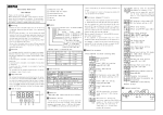
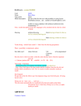
Type of the boilers
SLG Falcon 24, 36, 44
Wall hung condensing gas appliance for hot water central
heating.
SLG Falcon 24K
Wall hung condensing gas appliance for hot water central
heating and for the production of domestic hot water.
SLG Falcon 36K
CONTENTS
1.
Explanation of symbols in user manual and safty information ...................................................................... 6
1.1.
Explanation of symbols .......................................................................................................................... 6
Warnings ......................................................................................................................................................... 6
Important information .................................................................................................................................... 6
Instruction ....................................................................................................................................................... 6
1.2.
Important safety informations .............................................................................................................. 7
Instruction in case of gas odour ...................................................................................................................... 7
Instruction in case of smelling flue gas leaking from the boiler ...................................................................... 7
Damages caused by faulty handling ................................................................................................................ 7
Dangers conserning gas explosion .................................................................................................................. 7
The boiler installation, how to move it to an other place. The boiler and its environment .......................... 7
2.
3.
Proper use of the boiler and certification ....................................................................................................... 8
2.1.
Proper use of the boiler ......................................................................................................................... 8
2.2.
CE declaration of conformity ................................................................................................................. 8
2.3.
Boiler types ............................................................................................................................................ 8
2.4.
Avoid the damages coused by freez ...................................................................................................... 8
Boiler handling, usage ..................................................................................................................................... 9
3.1.
Boiler connections ................................................................................................................................. 9
SLG Falcon 24,36 heating boiler ...................................................................................................................... 9
SLG Falcon 24K, 36K heating – DHW boiler .................................................................................................... 9
SLG Falcon 44 heating boiler ......................................................................................................................... 10
3.2.
Steps before switching on the boiler ................................................................................................... 10
Cut-off valves control .................................................................................................................................... 10
Water pressure control of the heating system ............................................................................................. 10
3.3.
Control panel usage ............................................................................................................................. 11
Operating buttons overview ......................................................................................................................... 11
Digital display overview ................................................................................................................................ 12
Operating modes, handling ........................................................................................................................... 12
Adjusting the temperature of the heating water .......................................................................................... 13
Gas burner automatic turning on .................................................................................................................. 13
Information button ....................................................................................................................................... 13
Control mode ................................................................................................................................................ 14
4.
Failure codes and their meanings ................................................................................................................. 15
4.1.
Failure codes required user’s intervention .......................................................................................... 15
E01 – Lack of flame ....................................................................................................................................... 15
E02 – faulty flame indication......................................................................................................................... 15
E03 – Overheating protection ....................................................................................................................... 15
E05 – Fan failure ............................................................................................................................................ 15
E08 – Flame circle failure .............................................................................................................................. 15
E09 – Gas valve failure .................................................................................................................................. 15
E12 – Internal failure ..................................................................................................................................... 15
E15 – Heating Flow sensor failure ................................................................................................................ 16
E16 – Failed test of the heating flow temperature sensor............................................................................ 16
E17 – Failed test of the heating return temperature sensor ........................................................................ 16
E18 – Failed test of faulty sensor control ...................................................................................................... 16
E21 – Control board failure ........................................................................................................................... 16
E33 – Heating return temperature sensor failure ......................................................................................... 16
E35 – Heating Flow temperature sensor failure ........................................................................................... 16
4.2.
Failure codes resulting boiler block ..................................................................................................... 16
F07 – High fluegas temperture...................................................................................................................... 16
F13 – Unplug the boiler ................................................................................................................................. 17
F34 – Low power supply................................................................................................................................ 17
F37 – Low water pressure ............................................................................................................................. 17
F39 – Outside sensor failure ......................................................................................................................... 17
F40 – High water pressure ............................................................................................................................ 17
F41 – The filling valve operates ..................................................................................................................... 17
F42 – Failed filling .......................................................................................................................................... 17
F43 – Low water pressure after automatic filling ......................................................................................... 17
F47 – Water pressure sensor is not contacted.............................................................................................. 18
F50 – Domestic hot water (solar) sensor failure ........................................................................................... 18
F51 – Solar panel sensor failure .................................................................................................................... 18
F52 – Domestic hot water sensor failure ...................................................................................................... 18
F53 – Fluegas temperature sensor failure .................................................................................................... 18
F81 – Waiting for sensor testing ................................................................................................................... 18
5.
Maintenance ................................................................................................................................................. 19
5.1.
Periodic maintenance, inspection ....................................................................................................... 19
5.2.
Tasks during maintenance and ispection ............................................................................................ 19
Pressure control of the expansion tank ........................................................................................................ 19
Electrical wires and connections control ...................................................................................................... 19
Heat exchanger control ................................................................................................................................. 19
Burning system control ................................................................................................................................. 20
Condensing syphon cleaning ......................................................................................................................... 20
5.3.
6.
Proof of maintenance completion ....................................................................................................... 21
Switching off the boiler for longer period ..................................................................................................... 22
7.
First ignition of your boiler, Your service contact ......................................................................................... 23
8.
Notes and reminders ..................................................................................................................................... 24
9.
The protocol of the first ignition ................................................................................................................... 25
USER’S MANUAL
V1.0
1. EXPLANATION OF SYMBOLS IN USER MANUAL AND SAFTY INFORMATION
1.1.
EXPLANATION OF SYMBOLS
WARNINGS
The warnings in the text are marked with warning triangle and framed.
The required actions and consequences of those failure are included in the framed text.
IMPORTANT INFORMATION
Important information concerning people and surrounding objects (not dangerous
warnings)
INSTRUCTION
Instructions how to operate the boiler.
6
SLG Falcon wall-hang condensing gas boiler
USER’S MANUAL
1.2.
V1.0
IMPORTANT SAFETY INFORMATIONS
INSTRUCTION IN CASE OF GAS ODOUR
-
Turn off the gas tap!
-
Extinguish any open flames!
-
Open doors and windows! Fresh the air in the room!
-
Do not use electrical appliances which could be given off sparkle!
-
Notify the gas supplier or if the error occured in the gas boiler please contact
with the service expert of SL Group!
INSTRUCTION IN CASE OF SMELLING FLUE GAS LEAKING FROM THE BOILER
-
Switch the boiler OFF!
-
Open doors and windows! Fresh the air in the room!
-
Contact with the service expert of SL Group!
DAMAGES CAUSED BY FAULTY HANDLING
Failures caused by improper handling may result personal injury and material demages.
The manufacturer does not take responsibility for demages due to improper handling.
Make sure your children do not handle the boiler!
Make sure only that person handles the boiler who can do it properly!
DANGERS CONSERNING GAS EXPLOSION
The maintain and work in your gas system is allowed only for the official SL Group’s
expert who has the special license.
THE BOILER INSTALLATION, HOW TO MOVE IT TO AN OTHER PLACE.
THE BOILER AND ITS ENVIRONMENT
The boiler can be installed by official SL Group service expert only.
Do not change the fume pipes!
Do not obstruct the proper functioning of the safety equipments!
Do not store or use flammable materials (paper, thinner, paint) near the boiler!
SLG Falcon Wall-hang condensing gas boier
7
USER’S MANUAL
V1.0
2. PROPER USE OF THE BOILER AND CERTIFICATION
2.1.
PROPER USE OF THE BOILER
The boiler can be installed only in a closed heating system.
The manufacturer does not take responsibility for any failure due to use the boiler in
open heating system.
The boiler can be operated for domestic use only.
The boiler must not be used for producing industrial heat.
Information for the maximum/limited operating conditions contained in the book of
„Installation and maintenance instructions” issued for the attention of service experts.
2.2.
CE DECLARATION OF CONFORMITY
This product is - in its structure and operation - corresponding to the relevant
European directives, which is certified CE certification.
The boiler was tested by the following standards and specifications:
LVD 2006/EC, EMC 2004/108/EC, PED 97/23/EC, GAD 2009/142/EC
2.3.
BOILER TYPES
SLG Falcon 24, 36, 44
Wall hang condensing gas boiler for hot water central heating
SLG Falcon 24K
Wall hang condensing gas boiler for hot water central heating
and domestic hot water producing with plate heat exchanger
SLG Falcon 36K
2.4.
AVOID THE DAMAGES COUSED BY FREEZ
If the boiler will not operate for longer time the heating system and the boiler must drain to avoid the damages
coused by the freezing.
To draing the boiler and the heating system switch the boiler off and use the draing valve to empty the boiler.
After the drain procedure close the drain tap and the gas tap.
Drain the heating system also.
8
SLG Falcon wall-hang condensing gas boiler
USER’S MANUAL
V1.0
3. BOILER HANDLING, USAGE
3.1.
BOILER CONNECTIONS
SLG FALCON 24,36 HEATING BOILER
A – Heating flow connection (1”)
B – Gas connection (3/4”)
C – Cold water supply connection
D – Heating return connection (1”)
E – Condensing water drain connection (Ø32)
G – Filling valve
SLG FALCON 24K, 36K HEATING – DHW BOILER
A – Heating flow connection (1”)
B – Gas connection (3/4”)
C – Cold water supply connection (1/2”)
D – Heating return connection (1”)
E – Condensing water drain connection (Ø32)
F – DHW connection (1/2”)
G – Filling valve
SLG Falcon Wall-hang condensing gas boier
9
USER’S MANUAL
V1.0
SLG FALCON 44 HEATING BOILER
A – Heating flow connection (1”)
B – Gas connection (3/4”)
D – Heating return connection (1”)
E - Condensing water drain connection (Ø32)
3.2.
STEPS BEFORE SWITCHING ON THE BOILER
CUT-OFF VALVES CONTROL
Check the cut-off valves at the boiler connections.
Make sure that they are open.
(In open status the arms of the ball-valves point to the flow direction)
WATER PRESSURE CONTROL OF THE HEATING SYSTEM
Check the heating system pressure, which is 1-1,2 bar in cold status depending on the size
of the system.
Make sure that the pressure should not be higher than this value since the boiler is in
operation and when the water temperature increases its pressure also increases.
If the pressure exceeds 3 bar in the boiler or in the heating system the built-in safety valve
starts to operate and in order to reach the safety water pressure unload the water
through the ’E’ condensing water drain connector to reach the optimal pressure.
Make sure that the 'E' condensing drain connection leading the water to a safe area (f.
exp. sewage).
If the system water pressure is low the refill is necessary.
Only the cold boiler allowed to be refilled with heating water.
The refilling into hot boiler results the failure of the appliance (cracking of the internal
components).
These kind of damages are not covered by responsibility of the manufacturer and not
10
SLG Falcon wall-hang condensing gas boiler
USER’S MANUAL
V1.0
considered under warranty!
To refill the boiler use the ’G’ filling valve situated on the bottom of the appliance.
The boiler maximum operating pressure is 3 bar. Be careful that this value is not allowed
to exceed during filling.
Make sure that the water pressure does not exceed the specified 1-1,2 bar during filling
the cold appliance.
If the pressure exceeds 3 bar in the boiler or in the heating system the built-in safety valve
starts to operate and in order to reach the safety water pressure unload the unnecessary
water through the ’E’ condensing water drain connector.
When the filling is finished close the filling valve!
3.3.
CONTROL PANEL USAGE
OPERATING BUTTONS OVERVIEW
A – Domestic hot water temperature adjusting (+/-)
B – Heating water temperature adjusting (+/-)
C – Information
D – Reset
E – On/Off and operating mode changing button
F – Digital display
SLG Falcon Wall-hang condensing gas boier
11
USER’S MANUAL
V1.0
DIGITAL DISPLAY OVERVIEW
A – Domestic hot water operating mode
B – Burner output indicator
C – Service request (call your service partner)
D – Pressure indicator
E – Solar operation mode
F – Temperature indicator
G – Heating operation mode
H – Reset (press the Reset button)
I – Number / Code display
The digital display has a blue backlight.
The backlight turns on by pressing a button and turns off automatically after 15 seconds if
you do not press any of the button.
OPERATING MODES, HANDLING
Status : OFF
Ignoring heat requests, except for domestic hot water and frost protection of heating.
To activate the mode, press the 'E' marked button.
Status: STAND BY
In OFF status press the ’E’ marked button to change to Stand by and chose from the
following modes:
Winter: Domestic hot water and heating operation are allowed
Summer: Only the domestic hot water is allowed.
12
SLG Falcon wall-hang condensing gas boiler
USER’S MANUAL
V1.0
Room thermostat or OpenTherm controller unit are suitable to indicate the heating
request for the boiler controller.
The sensors closing in room thermostat indicates the heat request for the controller.
In winter operation mode the display shows a possible status of a valid heat request.
If a higher priority request is received, the process is discontinued and the controller
changes to serve the higher priority request.
Display in summer mode without heating request.
ADJUSTING THE TEMPERATURE OF THE HEATING WATER
Use the ’B’ marked buttons to increase (+) or decrease (-) the temperature of heating
water.
For pressing +/- buttons the display shows a flashing temperature indicator to help the
adjustment of the needed temperature with 1°C accuracy.
After 5 seconds, if you do not press any of the ’B’ buttons the display reverts to the
starter status.
Use the ’A’ marked buttons to increase (+) or decrease (-) the temperature of domestic
hot water.
For pressing +/- buttons the display shows a flashing temperature indicator to help the
adjustment of the needed temperature with 1°C accuracy.
After 5 seconds, if you do not press any of the ’A’ buttons the display reverts to the
starter status.
GAS BURNER AUTOMATIC TURNING ON
When the controller receives a real heating request the ignition of gas burner is started.
In case of ignition failure the controller attempts the re-ignition in specified numbers.
If all the ignitions are failed the display shows
failure code.
INFORMATION BUTTON
For pressing ’C’ information button the display shows the following data:
For single pressing of Information button the display shows the temperature measured by
solar sensor.
For double pressing of Information button the display shows the temperature measured
by outside temperature sensor
A possible status of the display.
SLG Falcon Wall-hang condensing gas boier
13
USER’S MANUAL
V1.0
The display status after pressing the Information button.
CONTROL MODE
Enter directly to the Control mode by pressing Information button for 10 seconds.
After selecting the Control mode the following sign appears on the display: „
”
In this mode you can get information about DHW temperature adjusting +/- by pressing
’A’ button and about heating water temperature adjusting +/- by pressing ’B’ button.
You can get information about the following parameters:
-
14
Heating flow sensor temperature (00-125°C)
Heating return sensor temperature (00-125°C)
DHW sensor temperature (00-125°C)
DHW sensor temperature (down tank 00-125°C)
Solar collector sensor temperature (00-125°C)
Flue gas sensor temperature (00-125°C)
Outside sensor temperature (double-digit)
Current speed of the fan (rpm x 10)
Current system pressure
Current flame intensity (uA x 10; between 00-99)
Control panel software version
SLG Falcon wall-hang condensing gas boiler
USER’S MANUAL
V1.0
4. FAILURE CODES AND THEIR MEANINGS
4.1.
FAILURE CODES REQUIRED USER’S INTERVENTION
On the display the failure codes required user’s intervention are started with ’E’.
To unlock the failure codes press the reset button or contact with service expert of SL
Group.
E01 – LACK OF FLAME
Lack of flame failure. The flame is not detected and all the retries are failed.
In this failure status the boiler does not operate, to restore the normal operation press
the ’reset’ button.
E02 – FAULTY FLAME INDICATION
The controller detects flame , but there is no real heat request (from the room
thermostat or DHW side).
In this failure status the boiler does not operate, to restore the normal operation press
the ’reset’ button.
E03 – OVERHEATING PROTECTION
The heating flow or return sensor measures too high temperature.
In this failure status the boiler does not operate, to restore the normal operation press
the ’reset’ button.
E05 – FAN FAILURE
The controller does not receive valid signal from the fan.
In this failure status the boiler does not operate, to restore the normal operation press
the ’reset’ button.
E08 – FLAME CIRCLE FAILURE
The detected flame level is outside of the specified range which indicates a failure in
either of electronic components.
E09 – GAS VALVE FAILURE
The controller receives invalid signal from the gas valve.
E12 – INTERNAL FAILURE
Intenal failure is occured.
SLG Falcon Wall-hang condensing gas boier
15
USER’S MANUAL
V1.0
E15 – HEATING FLOW SENSOR FAILURE
Press ’reset’ button.
E16 – FAILED TEST OF THE HEATING FLOW TEMPERATURE SENSOR
Failed test of the heating flow temperature sensor.
Press ’reset’ button.
E17 – FAILED TEST OF THE HEATING RETURN TEMPERATURE SENSOR
Failed test of the heating return temperature sensor.
Press ’reset’ button.
E18 – FAILED TEST OF FAULTY SENSOR CONTROL
Press ’reset’ button.
E21 – CONTROL BOARD FAILURE
The ADC test ended with failure. There is an electrical problem.
E33 – HEATING RETURN TEMPERATURE SENSOR FAILURE
The signal was given by the heating return temperture sensor is outside of the specified
range.
In this status the heat requests are ignored.
If the temperature returns into the specified range the failure can be cancelled with
’reset’ button.
E35 – HEATING FLOW TEMPERATURE SENSOR FAILURE
The signal was given by the heating flow temperture sensor is outside of the specified
range.
In this status the heat requests are ignored.
If the temperature returns into the specified range the failure can be cancelled with ’reset
button’.
4.2.
FAILURE CODES RESULTING BOILER BLOCK
F07 – HIGH FLUEGAS TEMPERTURE
If the measured temperature drops below the adjusted value within 15 minutes, the
appliance restarts.
The failure can be cancelled with unplugging in that case if the temperature returns into
16
SLG Falcon wall-hang condensing gas boiler
USER’S MANUAL
V1.0
the specified range.
F13 – UNPLUG THE BOILER
Any attempt to cancel this error by pressing ’reset’ is unnecessary.
This failure can be cancelled by unplugging the boiler.
F34 – LOW POWER SUPPLY
If the boiler operates, the burner turns off.
The failure is ended, if the voltage returns to the specified value (above 170V AC).
F37 – LOW WATER PRESSURE
Check the pressure of the heating system.
Only the cold boiler allowed to be refilled with heating water.
The refilling into hot boiler results the failure of the appliance (cracking of the internal
components).
These kind of demages are not covered by responsibility of the manufacturer and not
considered under warranty!
To refill the boiler use the ’G’ filling valve situated on the bottom of the appliance.
The boiler maximum operating pressure is 3 bar. Be careful that this value is not allowed
to exceed during filling.
F39 – OUTSIDE SENSOR FAILURE
If the value measured by the sensor returns into the normal range, the failure is
cancelled. The operation range for the sensor is between -40°C and 50°C.
To cancel the failure the measured value has to be in the normal range.
F40 – HIGH WATER PRESSURE
Check the water pressure of the heating system.
If this problem occured more times please contact with the service expert of SL Group.
F41 – THE FILLING VALVE OPERATES
The boiler is under filling by the electronic filling valve.
F42 – FAILED FILLING
After the filling the system pressure does not reach the specified value.
Please contact with the service expert of SL Group.
F43 – LOW WATER PRESSURE AFTER AUTOMATIC FILLING
After the automatic attempt for filling the water pressure remains low.
SLG Falcon Wall-hang condensing gas boier
17
USER’S MANUAL
V1.0
F47 – WATER PRESSURE SENSOR IS NOT CONTACTED
The water pressure sensor does not find the contact with the boiler.
Please contact with the service expert of SL Group.
F50 – DOMESTIC HOT WATER (SOLAR) SENSOR FAILURE
To cancel the failure the measured value has to be in the normal range.
F51 – SOLAR PANEL SENSOR FAILURE
To cancel the failure the measured value has to be in the normal range.
F52 – DOMESTIC HOT WATER SENSOR FAILURE
To cancel the failure the measured value has to be in the normal range.
F53 – FLUEGAS TEMPERATURE SENSOR FAILURE
To cancel the failure the measured value has to be in the normal range.
F81 – WAITING FOR SENSOR TESTING
18
SLG Falcon wall-hang condensing gas boiler
USER’S MANUAL
V1.0
5. MAINTENANCE
5.1.
PERIODIC MAINTENANCE, INSPECTION
The periodic maintenance and inspection of your appliance is very important in order to
have the boiler in safety and reliable status. The maintenance has to be done by official
service expert of SL Group.
5.2.
TASKS DURING MAINTENANCE AND ISPECTION
Hereby you find the tasks have to be done during maintenance and inspection. These
processes are very important for safety operation.
PRESSURE CONTROL OF THE EXPANSION TANK
Have to be checked that the expansion tank pressure corresponding to the specified value.
This pressure value is between 0,8-1 bar. If the pressure is below the specified value the
air have to be refilled.
In case of wrong/faulty expansion tank the system pressure may exceeds the safe value at
high temperature which leads to the activation of safety valve. If this occurs, in the cold
boiler the pressure may falls below the minimum level thus an electronic failure indicated
on the display.
In case of faulty expansion tank it has to be changed.
ELECTRICAL WIRES AND CONNECTIONS CONTROL
Have to be checked the status of internal electrical wires, and their proper distance from
any of hot spare parts.
Have to be checked the electrical connections at sensors, pump and the engine for three
ways valve.
HEAT EXCHANGER CONTROL
In a well adjusted appliance the heat exchanger does not need any special maintenance.
Have to be checked the fume ways and if there are soot or subsidence it is neccessary to
clean the whole heat exchanger.
The subsidences make more difficult for the fume to going out through the chimney,
furthermore worsen the heat unload ability thus the efficiency of the heat exchanger
reduces.
In case of smaller contamination it is enough to remove the burner and clean the fume
ways of the heat exchanger through the burner slot. In this case make sure that the water
can leak by the condensing syphon to the right place.
In case of huge contamination of the heat exchanger it could be taken out from the
appliance. It is necessary to remove the condensing plate before the extensive cleaning of
the whole heat exchanger.
Have to be checked the heat exchanger on water side.
SLG Falcon Wall-hang condensing gas boier
19
USER’S MANUAL
V1.0
The accumulated contaminations and scale in the heat exchanger reduce the cross section
of flow and results lower cooling for the heat exchanger. It leads to cracking of the heat
exchanger.
The failures due to the contaminations of the heat exchanger are not considered under
warranty.
BURNING SYSTEM CONTROL
In a well adjusted appliance the burner system does not need any special maintenance.
Check the clearness of the fan.
CONDENSING SYPHON CLEANING
At the end of the maintenance (after the cleaning of the heat exchanger) the condensing
syphon also has to be cleaned properly in order to be free way for leaking of condensing
water produced during operation.
20
SLG Falcon wall-hang condensing gas boiler
USER’S MANUAL
5.3.
V1.0
PROOF OF MAINTENANCE COMPLETION
To verify the periodic maintenance and inspection let’s fill-in the below table by the
service expert who services your appliance.
SLG Falcon Wall-hang condensing gas boier
Checking the possible
leakages
Cleaning out the condensing
trap
Checking the burner unit
Checking the primary heat
exchanger
Serial Nr.
Checking the electric wires
and its connections
Checking the pressure of the
expansion tank
SLG Falcon ________
Verification of work
Date of completion of work
Gas boiler type:
21
USER’S MANUAL
V1.0
6. SWITCHING OFF THE BOILER FOR LONGER PERIOD
If the boiler will not operate for longer time the heating system and the boiler must drain
to avoid the damages coused by the freezing.
The stept of the swittching off for longer period:
Close the gas tap,
Drain the water from the heating system and from the boiler,
Close the tap of the cold water supply and the other taps also,
Switch the boiler off and unplug from the mains.
22
SLG Falcon wall-hang condensing gas boiler
USER’S MANUAL
V1.0
7. FIRST IGNITION OF YOUR BOILER, YOUR SERVICE CONTACT
Because of the needed maintenance, inspections and repairs to be done professionally
please hereby note the contact details of the service expert of SL Group who installed your
boiler. Furthermore please note the data of your appliance too.
Service expert name:
Service company name:
Phone Nr. 1:
Phone Nr. 2:
Boiler type:
Installation date:
SLG Falcon Wall-hang condensing gas boier
23
USER’S MANUAL
V1.0
8. NOTES AND REMINDERS
24
SLG Falcon wall-hang condensing gas boiler
USER’S MANUAL
V1.0
9. THE PROTOCOL OF THE FIRST IGNITION
SLG Falcon Wall-hang condensing gas boier
25
USER’S MANUAL
V1.0
Send a copy of the Protocol to the SL Group Fűtéstechnika Kft!
26
SLG Falcon wall-hang condensing gas boiler