1
ADAS310: Beam emission spectroscopy process beam stopping and emission : H-beam
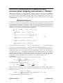
The program calculates the excited population structure, effective ionisation and recombination
coefficients of hydrogen atoms or hydrogenic ions in an impure plasma. A very many n-shell bundle-n
approximation is used. The hydrogen atoms may be part of the thermal plasma or may be in a beam.
The latter case is the only one of relevance for this manual, however the full flexibility of the program
has been retained.
Background theory:
For hydrogen or hydrogenic ions in a plasma, the largest collision cross-sections are those for which
n=n' and l=l'±1. For these cases the transition energy is nearly zero and the cross-sections are so large
for electron and ion densities of relevance for fusion that it is very good approximation to assume
relative statistical population for the l-states. Thus for hydrogenic systems only populations of
complete n-shells need be evaluated, the bundle-n approximation. The equilibrium populations of the
n-shells, Nn, are the solution of the statistical balance equations
∑[ A
n '→ n
n '> n
+ u(ν ) Bn '→ n + N e q n( e'→) n + N e q n( 'p→) n ] N n '
)
( p)
+ ∑ [u(ν ) Bn ''→n + N e q n( e''→
n + N e q n ''→ n ] N n ''
n ''< n
+ N e N + α n( r ) + N e2 N + α (n3) + N e N + ∫ u(ν ) Bκ →n dκ
p)
= {∑ [u(ν ) Bn→n ' + N e q n( e→) n ' + N e q n( →
n' ]
4.10.1
n '> n
+
∑[ A
n ''< n
n→ n ''
+ u(ν ) Bn→n '' + N e q n( e→) n '' + N e q n( →p)n '' ]
p)
+ ∫ u(ν ) Bn→κ dκ + N e q n( e→) ε + N e q n( →
ε }N n
N n is the population of the state X n+ z0 −1 and N + of the parent ion X + z0 . N e is the free electron
( e)
( p)
density and N p the free proton density. A and B are the usual Einstein coefficients, q and q
(r )
( 3)
denotes collisional rates due to electrons and protons, α n and α n denote radiative and three-body
recombination and u( ν) is the energy density of the radiation field. There is one such equation for
each value of n from 1 to ∞. The equations may be extended by including reactions for other impurity
ions additional to the protons. The radiation field presence in the equations is not of direct relevance to
hydrogen population modelling in a fusion plasma, but it can be exploited in a purely technical manner
to separate the influence of different driving populations in the collisional-radiative sense.
Gaunt factors
It is convenient to express the coefficients in terms of Gaunt factors. Thus
16α 4 c
z 04 g nI ,n '
3
4.10.2
An→n ' =
n' < n
2
2
3 3πa 0 n n' (n − n' )
and the Einstein B coefficients are given by
8 πhν3
n2
=
4.10.3
Bn→n ' = An→n '
B
Bn→n'
n '→ n
c3
n '2
2
2
2
where ν = ( z0 I H / h )(1 / n ' −1 / n ) is the frequency of the n → n' photon. With a Planck
radiation field of energy density u( ν) at temperature Tr and dilution W , the photo-excitation rate
coefficient is given by
u(ν ) Bn '→n
16α 4 c Wz04 g nI ,n '
=
/ [exp(hν / kTr ) − 1] 4.10.4
3
2
2
3 3πa 0 nn' (n − n' )
The stimulated emission rate coefficient is given by
ADAS User manual
Chap4-10
17 March 2003
16α 4 c Wz04 g nI ,n '
u(ν ) Bn '→n =
/ [exp(hν / kTr ) − 1] 4.10.5
3
2
2
3 3πa 0 nn' (n − n' )
I
The ADAS library contains subroutines for evaluation of the bound-bound Gaunt factors gn ,n ' .
In a similar manner the bound-free rates are obtained. The photo-ionisation rate coefficient from the
level n is
8α 4 c Wz04
∫ u(ν ) Bn→κ dκ = 3 3πa n 5
0
∞
∫
I n / kTr
g nII,κ dx
4.10.6
x (e x − 1)
The stimulated recombination coefficients is
πa 02 I H
∫ u(ν ) Bn→κ dκ = 8 kTe
3/ 2
8α 4 c Wz04
3
3 3πa 0 n
∞
exp( I n / kTe )
g nII,κ exp( − Tr x / Te )dx
∫
I n / kTr
4.10.7
x (e x − 1)
and the radiative recombination coefficient is
α
πa 2 I
= 8 0 H
kTe
(r )
n
3/ 2
8α 4 c z 04
3
3 3πa 0 n
∞
exp( I n / kTe )
∫
4.10.8
g nII,κ exp( − x )dx
x
I n / kTe
where I n = z0 I H / n , Te is the Maxwellian free electron temperature. The ADAS library contains
2
2
II
subroutines for evaluation of the bound-free Gaunt factors gn ,κ . The radiation dilution and radiation
temperature are relevant only to hydrogen in astrophysical plasmas. Thus the general dilution factor
for the beam case is set to zero. It is useful however to be able to artificially depopulate the ground
level of hydrogen so as to isolate the contributions to populations of excited levels of hydrogen coming
from recombination alone. This is achieved by having a separate dilution factor applying to photoionisation from the ground level which can be switched on and off. The only requirement here is that
this dilution factor and the associated radiation field temperature be large. Pre-set values in ADAS310
are suitable for most purposes.
The de-excitation rate for hydrogenic ions by electrons is
q
(e)
n '→ n
I
2 8 2 πα ca 02 n' 3 n 5 g n ,n ' I H
=
2 2 4 2
3
3
(n' − n ) z 0 kTe
1/ 2
P( ∆E n,n ' / kTe )
4.10.9
for n' > n and the excitation rate is
q
(e)
n→ n '
I
2 8 2 πα ca 02 n' 5 n 3 g n ,n ' I H
=
2 2 4 2
3
3
(n' − n ) z 0 kTe
1/ 2
4.10.10
exp( − ∆E n ,n ' / kT ) P ( ∆E n ,n ' / kTe )
Particularly simple expressions for P are given by Van Regemorter. In general an effective P-factor is
deduced from more complex collision cross-section calculations or experimental cross-section
measurements. similar formulation may be used for proton collision rates.
The electron collisional ionisation rate coefficient may be described by
q
(e)
n→ ε
I
= 8 πα ca H
kTe
2
0
1/ 2
n2
exp( − I n / kTe )
z 02
∞
4.10.11
∫ G exp( −ζ )dζ
0
and the three-body recombination coefficient by
ADAS User manual
Chap4-10
17 March 2003
2
I H n4 ∞
4.10.12
α = 2 π (α ca )
G exp( −ζ )dζ
kTe z 02 ∫0
with ζ = (Wn / I n − 1) / kTe and
W / I − 1
1
Wn / I n
ln(Wn / I n ) + I IP (Wn ) 4.10.13
G = n n
−
2
4
Wn / I n + 1 (Wn / I n + 1)
IP
in the Exchange Classical Impact Parameter ECIP approximation. I is the impact parameter part.
( 3)
n
6
2
5
0
b-factors and scaling
It is convenient to rewrite the statistical balance equations in terms of the deviations of the populations
from those which would occur in thermodynamic equilibrium. The deviation bn is defined by
3/ 2
πa 2 I
4.10.14
N n = N e N + 8 0 H n 2 exp( I n / kTe ) bn
kTe
Also it is convenient to introduce cn = bn − 1 and scaled temperatures and densities
kT 1
kT 1
π πa 03 N e
4.10.15
t e = e 2 , t r = r 2 and ρ e = 2 5
3 α 3 z 07
I H z0
I H z0
with similar forms for the proton temperature and density. In these terms the statistical balance
equations become particularly suitable for calculation.
Solution of the collisional-radiative equations
The general solution of the statistical balance equations to obtain collisional-radiative coefficients and
populations is described in detail in the description of ADAS208. The methods of condensation,
projection and expansion which give flexibility in the treatment of metastables and in the merging of
low resolution and high resolution population models are also described there. For the case of
hydrogen in beams entering fusion plasmas, the bundle-n level of resolution is appropriate for all nshells (subject to refinements described below of the key transitions) provided the interest is in beam
stopping and integral beam emission. Nonetheless, observations show that principal quantum shell
radiative transitions by beam atoms are spectrally resolved into motional Stark multiplets. Using the
methods of projection and expansion, the bundle-n solution can be expanded over low n-shell Stark
manifolds for a fuller study. ADAS310 has some capability for supporting such studies which it does
by accessing an ‘expansion definition file’ and by archiving the ‘condensed-projection matrices’.
These aspects have been de-activated for the present version of ADAS310 (although the expansion
definition file is still requested).
Approximations for collision cross-sections
Internal routines calculate default values for electron and ion impact excitation and ionisation in a
number of approximations. For electron impact excitation between nearby n-shells ( ∆n ≤ m ~ 2 ),
the impact parameter approximation (Burgess and Summers, 1976) is used. The order of the
quadrature over the cross-section to produce the rate coefficients may be altered but the highest
precision is generally used. For ∆n > m the formulae of Percival and Richard (1970) are available or
the simpler Van Regemorter (1962) approximation may be used. For ion impact excitation, crosssections are included for ∆n ≤ m' ~ 2 with the expressions of Lodge et al. (1976) or Vainshtein as
alternatives..
Supplementary precision data
The general purpose routines described above are satisfactory for generating collision cross-section
data at moderate accuracy for the very many n-shell atom population structure. However the precision
may be improved for excitation, ionisation and charge transfer involving the ground level and possibly
other low n-shells. Such improvement is particularly important for beam stopping coefficients and
active or passive Lyman and Balmer line spectroscopy. Systematic improvement is implemented by
drawing on the ADAS ion/atom and ion/electron collision database. A supplementation subroutine
(SUPPH1 for H0 (HI) ), which is subject to periodic adjustment executes the data acquisition under the
following classes
class
returned data
source
electron excit.
excit. & dexcit. maxwellian.
specific ion files (adf04)
rate coefficients
bundle-n form
electron ions.
ionis. maxwellian
szd files (adf07)
rate coefficient
ADAS User manual
Chap4-10
17 March 2003
proton excit.
excit. & dexcit. displaced
sia#h files (adf02)
maxwell. rate coefficients
proton ionis.
ionis.. displaced
sia#h files (adf02)
maxwell. rate coefficient
impurity excit. excit. & dexcit. displaced
sia#h files (adf02)
maxwell. rate coefficients
impurity ionis. ionis.. displaced
sia#h files (adf02)
maxwell. rate coefficient
The supplementary data is introduced, for example as an effective P factor
Pn,n' = qn( s→) n' / {(2 πα ca02 )
I H / kT [( I H / ∆En ,n ' ) f n →n ' ]exp( − ∆En ,n ' / kT )]}
4.10.16
for excitation which replaces the moderate accuracy formulaic value if available. For the hydrogenic
ion as a plasma species, state selective charge exchange recombination data to excited levels for
hydrogen donors may be included and these data are accessed directly from the appropriate file (adf01)
Distinctions in analysis for hydrogen in beam or plasma
The program can apply to hydrogen atoms in a thermal plasma or to hydrogen atoms in a beam. The
practical distinction is made by the assignment of a translational velocity for beam atoms. This
velocity is incorporated in the integrals of beam particle / plasma particle cross-sections over the
Maxwellian distributions in the thermal plasma. For hydrogen forming part of the thermal plasma, the
translational velocity is set to zero. In the latter circumstance, ion impact collision rates are very small
compared with electron impact rates. Also recombination (both free-electron capture and charge
exchange capture) become significant processes. For the hydrogen atoms in a fast beam,
recombination is not relevant and although formally present is ignored in the results. However the
translational velocity can make ion impact collisions more important than electron collisions.
Multiple impurities and zeff
In general several impurity species (nuclei) may be involved in collisionally inducing transitions. Of
these the hydrogen nuclei are often the most important and because of better availability of data and
approximations for proton induced rates, the protons are usually treated as a special (plasma) species
and the other species treated as the 'impurities'. Let the electron and proton number densities be N e
and N p respectively.
Let the set of impurities charges and fractions by number be
)
{z0(imp
, f i (imp ) ; i = 1,.., I } then the total impurity number density, zeff and component impurity
i
number densities are
I
) (imp )
N (imp ) = ( N e − N p ) / ( ∑ z0(imp
fi
)
i
i =1
I
) 2
zeff = ( N p + N (imp ) [ ∑ ( z0(imp
) f i (imp ) ]) / N e
i
4.10.16
i =1
N i(imp ) = f i (imp ) N (imp )
In the case of single impurity, which is frequently used as a single 'effective' impurity, it is convenient
to alter the definitions. Taking N e , N p and zeff as prescribed
z0(imp ) = ( zeff N e − N p ) / ( N e − N p )
4.10.17
N (imp ) = ( N e − N p ) / z0(imp )
determines the effective charge for the single impurity and its number density.
The beam stopping coefficient is the collisional radiative ionisation coefficient. However there is
sometimes confusion about its definition. Although hydrogen nuclei impact ionisation and charge
transfer are the most efficient reactions causing beam stopping, it is usual in fusion to define the
stopping coefficient with respect to the electron density. Thus the stopping rate (cm-3 s-1) is
N e N B S ( e ) with N B the neutral beam density. For ADAS310, this applies even if the stopping is
calculated for the case of a pure impurity with all the free electrons contributed by the impurity in
charge balance. Thus for a pure impurity of number density N I and nuclear charge Z , with effective
ionisation coefficient, S
ADAS User manual
(I)
, the stopping rate is N I N B S
Chap4-10
(I)
and S
(e)
= S (I) / Z .
17 March 2003
Population results and preparing tabulations
ADAS 310 is too slow in execution for a direct link to inter-pulse experiment analysis and so it is used
to prepare tabulations of effective beam stopping and beam emission coefficients for subsequent lookup. The effective coefficients are most sensitive to the beam particle energy and the plasma ion density
and less sensitive to plasma ion temperature and Z-effective. Suitable tabulations can therefore be built
on a reference set of plasma and beam conditions, a two-dimensional array of coefficients as functions
of beam energy and plasma density at the reference conditions of the other parameters and then onedimensional vectors of the coefficients as functions of each minor parameter at the reference condition
of all the other parameters. ADAS310 accepts as input the definition of these scans, establishes an
extended list of cases required to achieve these scans and then executes repeated population
calculations at each set of plasma conditions in the list. ADAS310 can compute the populations for
any mixture of light impurities (hydrogen to neon) in the plasma. It is impractical to deal with all
possible mixtures of impurities. It is our usual practice to execute ADAS310 in turn for each light
impurity from hydrogen to neon treated as a pure species. The mixed species effective coefficients are
constructed from these pure impurity solutions by the theoretical data acquisition routines. The main
population output is very complete and in principle contains all information on possible emitted
spectrum lines up to very high n-shells together with both ionisation and recombination collisionalradiative coefficients. It is archived as ADAS data format adf26. ADAS310 can also produce directly
the final tabulations of beam stopping coefficient according to ADAS data format adf21, however this
is normally done using the post-processor program ADAS312.
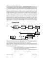
Program steps:
These are summarised in the figure below.
Figure 4.10
EHJLQ
HQWHU H[SDQVLRQ
!
DQG FKDUJH
H[FKDQJH ILOH
HQWHU SURFHVVLQJ
!
RSWLRQV
!
2EWDLQ RXWSXW
ILOH QDPHV
FKRLFHV
!
HVWDEOLVK
QXPEHU RI
SURFHVVLQJ
ORRSV UHTXLUHG
FRS\ LQSXW
UHSHDW
SDUDPHWHUV WR
!
WHPSRUDU\ ILOH
IRU YEQGOQ XVH
F\FOH RQRII VZLWFKHV
!
2XWSXW SDVVLQJ
ILOHV DQG EHDP
VWRSSLQJ ILOH
HQG
VRUW SRSXODWLRQ
EUHDN GRZQ
IRU SDVVLQJ
FDOO EXQGOHQ
SRSXODWLRQ
PRGHO YEQGOQ
ILOHV
Interactive parameter comments:
The program which makes use of data from archived ADAS data-sets initiates an interactive dialogue
with the user in three parts, namely, input data file selection, entry of user data and disposition of
output. The primary calculations may be conducted in foreground or background.
Move to the directory in which you wish the ADAS created files to appear. These include the output
text file produced after executing any ADAS program (paper.txt is the default), and up to four further
output data files. There is no graphical output from this program Initiate ADAS310 from the program
selection menus in the usual manner.
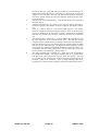
The file selection window appears first as illustrated below.
1.
At a) enter the beam species (H for hydrogen and its isotopes) and the
atomic charge of the beam species. Only data for neutral beam species is
present in the central ADAS database at this time.
2.
There are two data files to be selected, the expansion file and the charge
exchange file. The procedure is the same in both cases.
3.
Data root a) shows the full pathway to the appropriate data sub-directories.
Click the Central Data button to insert the default central ADAS pathway to
ADAS User manual
Chap4-10
17 March 2003
4.
5.
6.
7.
8.
ADAS User manual
the correct data type. Note that each type of data is stored according to its
ADAS data format (adf number). Click the User Data button to insert the
pathway to your own data. Note that your data must be held in a similar file
structure to central ADAS, but with your identifier replacing the first adas,
to use this facility.
The Data root can be edited directly. Click the Edit Path Name button first
to permit editing
Available sub-directories are shown in the large file display window b).
Scroll bars appear if the number of entries exceed the file display window
size.
Click on a name to select it. The selected name appears in the smaller
selection window c) above the file display window. Then its sub-directories
in turn are displayed in the file display window. Ultimately the individual
data-files are presented for selection. Data-files all have the termination
.dat.
The expansion file is selected at b). A special ADAS data type adf18 is used
for such ‘expansion’ and ‘cross-referencing’ files. They fall into various
categories, kept in sub-directories, according to where they map from and to.
Thus the sub-directory a09_a04 contains data sets mapping from the adf09
data type into the adf04 data type. We shall deal with the purposes of these
in the discussion of advanced population modelling in the next release. For
the moment note that bndlen_exp#h0.dat is the one needed here and it sits
alone as shown in the illustration. Always select it.
The charge exchange file is selected at c). Again this is not of importance
for neutral beam stopping. The charge exchange data set is required when
hydrogen nuclei can act as electron receivers from other species. You will
see no effect of your selection here on the beam stopping coefficient but the
selection is kept in for the future. Once a charge exchange data file is
selected, the set of buttons at the bottom of the main window become active.
Chap4-10
17 March 2003
9.
10.
Clicking on the Browse Comments button displays any information stored in
the selected charge exchange data-file. It is important to use this facility to
find out what is broadly available in the data-set. The possibility of
browsing the comments appears in the subsequent main window also.
Clicking the Done button moves you forward to the next window. Clicking
the Cancel button takes you back to the previous window
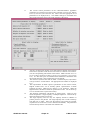
The processing options window has the appearance shown below
ADAS User manual
Chap4-10
17 March 2003
11.
The various control parameters of the collisional-radiative population
calculation are organised into three groups selected in turn by the buttons
General, Switches (I) and Switches (II). These cause the appropriate set of
parameters to be displayed at b). The default settings are reasonable and
they can be ignored as long as only beam stopping is the intent.
12.
Switches (I) allow some choices to do with electron collision cross-sections
and Switches (II) allow some choices to do with ion collision cross-sections.
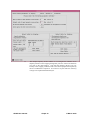
(see the corresponding sub-window inserts below Make sure that Access to
low level data is chosen at a) and Use beam energy informing cross-sections
at b). It is this latter piece of information that informs the calculation that
the neutral hydrogen is in the beam and not in the plasma.
The choices at c) above must then be made. Click the Impurity information
or Representative N-shell buttons. The appropriate sub-window is displayed
at c).
The representative N-shells requires specification of the lowest N-shell,
Highest N-shell and a set of sensibly spaced ‘representative’ N-shells
spanning the range. Make sure the lowest is 1 for hydrogen. Make the
highest around 110 and use about 20 representative levels. Use all levels up
to N=10 and then start to space more widely.
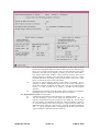
The Impurity information sub-window is shown below. There are two
modes of operation. Single impurity or Multiple impurities. Click the dropdown list button to make your choice.
The single impurity case has only one impurity nucleus in addition to
protons present in the plasma. The single impurity case is used to build up
such data sets in adf21. Note how the impurity and protons fit together
(equations 4.10.16 and 4.10.17 in the ADAS User Manual). The proton and
electron density choices to be made next influence this.
13.
14.
15.
16.
ADAS User manual
Chap4-10
17 March 2003
17.
ADAS User manual
The multiple impurity choice enables us to investigate the influence of an
impurity mixture on the stopping with greater precision. Edit in the fractions
you wish in the usual manner. Note that the impurity density acts nonlinearly in the stopping coefficient and so the linear superposition implied by
the use of ADAS304 is imprecise. It is however very fast which is necessary
in large scale experimental data analysis.
Chap4-10
17 March 2003
18.
At d) the choice of plasma and beam parameters for the scans are made
Click on the appropriate button to work on each scan in turn. Note that you
edit in a set of values and then choose one to be the reference value of that
parameter. The table may be edited by clicking on the Edit Table button..
The ADAS Table Editor window is then presented with the same set of
editing operations available as are described in bulletin nov18-94. Values
should be monotonic increasing. It has proved helpful to add a Clear Table
button to remove all entries in the output field.
19.
Note that a neutral hydrogen density in the beam is requested. This is
necessary to allow a mathematical separation of the various influences on
the neutral hydrogen population structure and is not an experimental beam
density. A value of order 106 or greater is suitable for the program
operation.
20.
Clicking the Done button causes the output options window to be displayed.
Remember that Cancel takes you back to the previous window.
The output options window is shown below.
21.
It follows the usual pattern except that there is no graphical output.
22.
The Run Summary is given in the output file specified at a). The Run
Summary Output button activates writing to a text output file. The file name
may be entered in the editable File name box when Run Summary Output is
on. If the file already exits a choice to Replace or Append may be made. The
default file name ‘paper.txt’ may be set by pressing the button Default file
name. A ‘pop-up’ window issues a warning if the file already exists and the
Append or Replace button has not been activated.
ADAS User manual
Chap4-10
17 March 2003
23.
24.
Four additional passing files may be produced which are placed in your pass
directory. The first passing file is of ADAS data format ADF26 and contains
line printer formatted pages of data, one page for each individual population
structure case run. The data held on these sheets is very comprehensive. By
appropriate choice of the parameters mentioned in the processing section
above and choice of input files, hydrogen in all its possible conditions in a
fusion plasma can be obtained (beam and non-beam).
Click the Run Now button to initiate the calculations. These are run in foreground since they are of fairly modest duration. A thermometer widget
illustrated below keeps you informed of the progress of the calculations.
ADAS310 : INFORMATION
$'$6 &$/&8/$7,216 81'(5:$< B 3/($6( :$,7
352&(66,1* &203/(7('
ADAS User manual
Chap4-10
17 March 2003
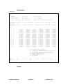
Illustration:
Table 4.10a.
EFFECTIVE CONTRIBUTION TABLE FOR ION PRINCIPAL QUANTUM SHELL POPULATIONS IN THERMAL PLASMA
HYDROGEN
Z0 = 1.00E+00
Z1 = 1.00E+00
TRAD = 1.00E+08 K
W = 0.00E+00
TE = 5.80E+07 K
NE = 1.00E+12 CM-3
TP = 5.80E+07 K
NP = 0.00E+00 CM-3
EH = 5.00E+03 EV/AMU
NH = 1.00E+06 CM-3
NH/NE = 1.00E-06
FLUX = 9.78E+13 CM-2 SEC-1
CHARGE EXCHANGE OFF: N1/N+ = 3.96967E-10
CM+3 SEC-1
RECOMB COEFF = 3.98614E-17 CM+3 SEC-1
IONIZ COEFF = 1.00415E-07
CHARGE EXCHANGE ON : N1/N+ = 1.01033E-06
CM+3 SEC-1
RECOMB COEFF = 1.01452E-13 CM+3 SEC-1
IONIZ COEFF = 1.00415E-07
I
1
2
3
4
5
6
7
8
9
10
11
12
13
14
15
16
17
18
19
20
21
22
N
1
2
3
4
5
6
7
8
9
10
11
12
15
20
30
40
50
60
70
80
90
100
F1
0.00000E+00
9.03269E+09
3.27110E+09
1.38276E+09
4.65572E+08
1.55704E+08
5.87510E+07
2.50081E+07
1.20056E+07
6.55794E+06
4.29257E+06
2.66749E+06
6.45607E+05
9.49494E+04
1.10830E+04
2.32656E+03
6.76789E+02
2.38809E+02
9.29529E+01
3.58867E+01
1.07020E+01
-1.50137E+00
F2
4.22257E+05
3.77642E+00
2.50566E+00
1.72873E+00
1.25911E+00
1.08781E+00
1.03338E+00
1.01425E+00
1.00684E+00
1.00373E+00
1.00244E+00
1.00151E+00
1.00036E+00
1.00005E+00
1.00001E+00
1.00000E+00
1.00000E+00
1.00000E+00
1.00000E+00
1.00000E+00
1.00000E+00
1.00000E+00
BN
N1
N+
NN
BN
EH
W
Z0
Z1
NIP
= 0
IVDISP= 1
ZEFF = 4.0
= 4.0
INTD
TS
=
=
3
IPRS
1.00D+08
=
W
1
=
F3
1.07427E+15
1.90419E+09
3.72697E+08
8.89060E+07
1.96737E+07
4.77562E+06
1.41410E+06
4.92186E+05
1.98482E+05
9.26893E+04
5.28243E+04
2.88629E+04
4.69556E+03
5.01251E+02
5.29440E+01
1.07290E+01
3.06759E+00
1.07145E+00
4.13889E-01
1.58384E-01
4.61460E-02
-8.06097E-03
=
=
=
=
=
=
=
=
=
ILOW
B(CHECK)
1.07472E+09
1.10339E+04
3.68009E+03
1.48767E+03
4.91313E+02
1.63175E+02
6.18052E+01
2.67728E+01
1.33349E+01
7.72209E+00
5.39216E+00
3.72541E+00
1.65733E+00
1.09648E+00
1.01126E+00
1.00236E+00
1.00069E+00
1.00024E+00
1.00009E+00
1.00004E+00
1.00001E+00
9.99998E-01
B(ACTUAL)
1.07472E+09
1.10339E+04
3.68009E+03
1.48767E+03
4.91313E+02
1.63175E+02
6.18052E+01
2.67728E+01
1.33349E+01
7.72209E+00
5.39216E+00
3.72541E+00
1.65733E+00
1.09648E+00
1.01126E+00
1.00236E+00
1.00069E+00
1.00024E+00
1.00009E+00
1.00004E+00
1.00001E+00
9.99998E-01
NN/(BN*N+)
9.40109E-16
3.75276E-15
8.44053E-15
1.50034E-14
2.34414E-14
3.37545E-14
4.59426E-14
6.00059E-14
7.59443E-14
9.37578E-14
1.13446E-13
1.35010E-13
2.10952E-13
3.75024E-13
8.43800E-13
1.50009E-12
2.34388E-12
3.37519E-12
4.59401E-12
6.00034E-12
7.59418E-12
9.37553E-12
F1*(N1/N+) + F2 + F3*(NH/NE)
POPULATION OF GROUND STATE OF ION
POPULATION OF GROUND STATE OF NEXT IONISATION STAGE
POPULATION OF PRINCIPAL QUANTUM SHELL N OF ION
SAHA-BOLTZMANN FACTOR FOR PRINCIPAL QUANTUM SHELL N
NEUTRAL HYDROGEN BEAM ENERGY
RADIATION DILUTION FACTOR
NUCLEAR CHARGE
ION CHARGE+1
=
0.00D+00
1
IONIP =
CION
=1.0
1
NIONIP=
CPY =1.0
2
W1
ILPRS =
=
1.00D+08
Notes:
ADAS User manual
Chap4-10
17 March 2003
1
ZIMP


![Procédure IMPR_RESU aux formats `RESULTAT` et `AST[...]](http://vs1.manualzilla.com/store/data/006368331_1-ae42a571e2c1f23d4b0aed84d99a540b-150x150.png)