1
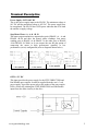
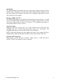
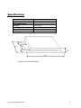
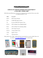
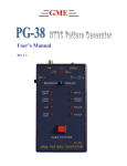
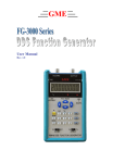
GME User’s Manual Rev 1.2 TEST INSTRUMENT SAFETY GUIDELINES WARNING An electrical shock of over 10 milliamps of current to pass through the heart will stop most human heartbeats. Voltage as low as 35 volts dc or ac rms should be considered dangerous and hazardous since it can produce a lethal current under certain conditions. Be sure to observe following safety precautions: 1. Do not expose high voltage needlessly in the equipment under test. Remove housings and covers only when necessary. Turn off equipment while making test connections in high-voltage circuits. Discharge high-voltage capacitors after removing power. 2. If possible, familiarize yourself with the equipment being tested and the location of its high voltage points. However, remember that high voltage may appear at unexpected points in defective equipment. 3. Use an insulated floor material or a large, insulated floor mat to stand on, and an insulated work surface on which to place equipment; make certain such surfaces are not damp or wet. 4. When using a probe, touch only the insulated portion. Never touch the exposed tip portion. 5. When testing ac powered equipment, remember that ac line voltage is usually present on some power input circuits such as the on-off switch, fuses, power transformer, etc. any time the equipment is connected to an ac outlet, even if the equipment is turned off. Limited One-Year Warranty GME Technology warrants to the original purchaser that this product and the component parts thereof, will be free from defects in workmanship and materials for a period of one years from the data of purchase. GME Technology will, without charge, repair or replace, at its’ option, defective product or component parts. Returned product must be accompanied by proof of the purchase date in the form a sales receipt. Term and Conditions The warranty period is based upon the invoice date of the original purchase by the end-user. Warranty only applies to defects in materials and/or workmanship, which occur during normal use. Warranty does not apply to those products that are damaged due to misuse, abuse, negligence or modification. Warranty does not extend to any damage that occurs in shipment or due to natural phenomenon (i.e. lightning or line surges). Warranty will be voided if the original serial number on the product is removed by accident or intentionally This warranty gives you specific rights and you may have other rights, which vary from state-to-state. Service & Repair The following are procedure for returning a GME product for servicing and repair. Turn around time for repair is normally within five (5) working days excluding shipping time. RMA Procedure Before sending your GME product in for service, be sure to contact GME Technology first to obtain a RMA number. If your product is still under warranty, please send in the product along with a copy of the receipt showing the date when the product was purchased. If the warranty has already expired, please ask for the repair cost when you contact GME Technology for the RMA number and include a check or money order for the repair cost when you send in the product. Please make check payable to: GME Technology You may send your GME product to our service & repair department at: GME Technology ATTN: Service & Repair Department 380 S. East End Ave., #H Pomona, CA 91766 Be sure to include a note showing your RMA number, your name, telephone number, return address, and a description of the problem with the product. For the most recent support information, please visit GME Technology website at www.gmetechnology.com/support Table of Contents Page Introduction …………………………………………………………………………. 1 Item Checklist ……………….…………………………………………………….... 1 Features ……………………………………………………………………………... 1 Installation ………………………………………………………………………….... 2 Terminal Description ….……………………………………………………...…….. 3-4 Specifications ………………….……………………………………………………... 5 GME Product Information …………………………………………………………… 6 Notes ……….………………….…………………………………………………….. 7 Introduction Thank you for purchasing the SD-220 Step Motor Driver. The SD-220 is a chopper type full or half step driver for use with 4, 6, and 8 wire step motors. It has opto-isolated step, direction and Enable/Disable inputs that can either be driven directly by TTL gates or by open collector transistor outputs. The power supply voltage can range from 18 VDC to 40VDC and maybe unregulated. The motor phase current is adjustable up to 2 Amp. The SD-220 is encapsulated in a sturdy heat conductive aluminum case, making it suitable for use in a harsh environment. Item Checklist SD-220 Step Motor Driver One User’s Manual Features Full / half step (selectable) bipolar chopper driver Driver for 2 or 4 phase stepper motor Power supply voltage range from 18 VDC to 40VDC (can be unregulated) Motor phase current up to 2 Amp (adjustable) Step rate ≤ 12 kHz Opto-isolated step clock input, direction inputs (CW/CCW), and Enable/Disable input that can either be driven directly by TTL gates or by open collector transistor outputs Encapsulated in a sturdy heat conductive aluminum case Installation * Switches located on the side of the unit www.gmetechnology.com 1 Terminal Description Power Supply: 18 TO 40V DC This is the power supply input to the SD-220. The minimum voltage is 18V DC and the maximum voltage is 40V DC. The power supply may be unregulated. The SD-220 has a LED power indicator that is lit when the unit has a supply voltage. Step Motor Phase +A, -A & +B, -B The motor output terminals are organized as pairs (PHASE +A, -A and PHASE +B,-B) and drive the motor's phase windings. One motor winding goes to PHASE +A & PHASE -A, the other goes to PHASE +B & PHASE –B. With 6 or 8 wire motors the user has the option of connecting the motor in high performance (parallel) or low performance (series) configuration (refer to diagrams shown below). 6 wire parallel 6 wire series 8 wire parallel 8 wire series OPTO +5V DC This input provides the power supply for the STEP, DIRECTION and Ena/Disable opto-couplers. It must be supplied from the user's 5 volt power supply. It provides power only to the anodes of the opto-coupler LEDs; electrically isolating the STEP, DIRECTION and Ena/Disable inputs from the other circuitry in the drive. www.gmetechnology.com 2 Ena/Disable The Enable/Disable input controls the motor. If this input is high, the motor will step with the clock. If this input is low, the motor will be turned off with no holding current and clock signals will be ignored. The input is TTL compatible and requires a current sink of about 10 mA to operate. Direction ( DIR CW/CCW ) The DIRECTION input is to determine which direction the motor will move. A high level on the DIRECTION terminal will result in clockwise motion while a low level will cause counter-clockwise motion. The input is TTL compatible and requires a current sink of about 10 mA to operate. Step Clock Input Stepping of the motor occurs on the '1 to 0' logic transition of the STEP input. The maximum step rate is 12 KHz when driven with a square wave. The input is TTL compatible and requires a current sink of about 10 mA to operate. NOTE: When stop applying step clock signals, the motor will be turned off with a holding current, make sure this input is HIGH to ensure opto-coupler LED is off. Full Step / Half Step Select When switch 1 is ON, full step is selected. When switch 1 is OFF, half step is selected. NOTE: The setting for switch 2 is ignored. www.gmetechnology.com 3 Specifications Resolution Supply Voltage Motor Phase Current Step Rate Operating Temperature Dimension Weight 1/2 (Min) ~ 1 (Max) step 18V ~ 40V DC 2A (max) - Adjustable 12 kHz (Max) 0 °C ~ +70°C 118mm (H) x 70mm (W) x 28mm (D) 0.7 lb * Units shown in mm (millimeter) www.gmetechnology.com 4 WWW.GMETechnology.COM For product updates and information CHECK OUT THESE OTHER TEST EQUIPMENT AVAILABLE FROM GME GME offers many different types of electronic test equipment to suit your needs. Here are some of the test equipment products we offer. Model Description HG139 HDTV Pattern Generator SG-10 10 MHz DDS Signal Generator 236 In-Circuit ESR & DCR Capacitor Tester PG-16A NTSC & Monitor Tester (Handheld Model) PG-68 NTSC & Monitor Tester (Benchtop Model) PG-38 NTSC Pattern Generator MT-160 Computer Monitor Tester LC200 Digital LC Meter C350 Capacitance Meter Other products such as digital / analog panel meters, step motor drivers are also available. Please visit our website at www.gmetechnology.com for complete detail. www.gmetechnology.com 5 Notes www.gmetechnology.com 6