1
bdi GDB
JTAG debug interface for GNU Debugger
PowerPC 6xx/7xx/82xx/83xx/7400/7410
User Manual
Manual Version 1.31 for BDI2000
©1997-2015 by Abatron AG
bdiGDB for BDI2000 (PowerPC 6xx/7xx/82xx/83xx/7400/7410)
User Manual
2
1 Introduction ................................................................................................................................. 3
1.1 BDI2000................................................................................................................................. 3
1.2 BDI Configuration .................................................................................................................. 4
2 Installation ................................................................................................................................... 5
2.1 Connecting the BDI2000 to Target ........................................................................................ 5
2.1.1 Changing Target Processor Type ................................................................................ 7
2.2 Connecting the BDI2000 to Power Supply ............................................................................ 8
2.3 Status LED «MODE»............................................................................................................. 9
2.4 Connecting the BDI2000 to Host ......................................................................................... 10
2.4.1 Serial line communication .......................................................................................... 10
2.4.2 Ethernet communication ............................................................................................ 11
2.5 Initial configuration of the bdiGDB system........................................................................... 12
2.5.1 Configuration with a Linux / Unix host........................................................................ 13
2.5.2 Configuration with a Windows host ............................................................................ 15
2.5.3 Recover procedure..................................................................................................... 16
2.6 Testing the BDI2000 to host connection.............................................................................. 17
2.7 TFTP server for Windows .................................................................................................... 17
3 Using bdiGDB ............................................................................................................................ 18
3.1 Principle of operation........................................................................................................... 18
3.2 Configuration File ................................................................................................................ 19
3.2.1 Part [INIT]................................................................................................................... 19
3.2.2 Part [TARGET] ........................................................................................................... 22
3.2.3 Part [HOST]................................................................................................................ 28
3.2.4 Part [FLASH] .............................................................................................................. 30
3.2.5 Part [REGS] ............................................................................................................... 34
3.3 Debugging with GDB ........................................................................................................... 36
3.3.1 Target setup ............................................................................................................... 36
3.3.2 Connecting to the target............................................................................................. 36
3.3.3 Breakpoint Handling................................................................................................... 37
3.3.4 GDB monitor command.............................................................................................. 37
3.3.5 Target serial I/O via BDI............................................................................................. 38
3.3.6 Embedded Linux MMU Support ................................................................................. 39
3.4 Telnet Interface.................................................................................................................... 41
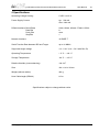
4 Specifications ............................................................................................................................ 44
5 Environmental notice................................................................................................................ 45
6 Declaration of Conformity (CE)................................................................................................ 45
7 Abatron Warranty and Support Terms .................................................................................... 46
7.1 Hardware ............................................................................................................................. 46
7.2 Software .............................................................................................................................. 46
7.3 Warranty and Disclaimer ..................................................................................................... 46
7.4 Limitation of Liability ............................................................................................................ 46
Appendices
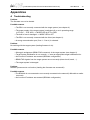
A Troubleshooting ....................................................................................................................... 47
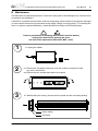
B Maintenance .............................................................................................................................. 48
C Trademarks ............................................................................................................................... 50
© Copyright 1997-2015 by ABATRON AG Switzerland
V 1.31
bdiGDB for BDI2000 (PowerPC 6xx/7xx/82xx/83xx/7400/7410)
User Manual
3
1 Introduction
bdiGDB enhances the GNU debugger (GDB), with COP debugging for PowerPC 6xx/7xx/82xx/83xx
based targets. With the built-in Ethernet interface you get a very fast code download speed. No target
communication channel (e.g. serial line) is wasted for debugging purposes. Even better, you can use
fast Ethernet debugging with target systems without network capability. The host to BDI communication uses the standard GDB remote protocol.
An additional Telnet interface is available for special debug tasks (e.g. force a hardware reset,
program flash memory).
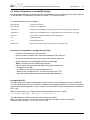
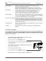
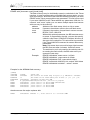
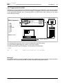
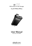
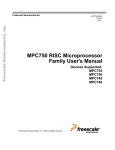
The following figure shows how the BDI2000 interface is connected between the host and the target:
Target System
MPC
8260
COP Interface
PC / Unix Host
BDI2000
GNU Debugger
(GDB)
Ethernet (10 BASE-T)
1.1 BDI2000
The BDI2000 is the main part of the bdiGDB system. This small box implements the interface between the JTAG pins of the target CPU and a 10Base-T Ethernet connector. The firmware and the
programmable logic of the BDI2000 can be updated by the user with a simple Windows based configuration program. The BDI2000 supports 1.8 – 5.0 Volts target systems (3.0 – 5.0 Volts target systems with Rev. B).
Note for 1.8V / 2.5V I/O voltage:
Some PowerPC designs work with 1.8V or 2.5V I/O voltage. This is not supported by the BDI2000
Rev. B. You need level shifters when using the BDI2000 Rev. B together with such a system.
© Copyright 1997-2015 by ABATRON AG Switzerland
V 1.31
bdiGDB for BDI2000 (PowerPC 6xx/7xx/82xx/83xx/7400/7410)
User Manual
4
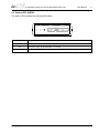
1.2 BDI Configuration
As an initial setup, the IP address of the BDI2000, the IP address of the host with the configuration
file and the name of the configuration file is stored within the flash of the BDI2000.
Every time the BDI2000 is powered on, it reads the configuration file via TFTP.
Following an example of a typical configuration file:
;bdiGDB configuration file for MPC8260-ADS board @40MHz
; ----------------------------------------------------[INIT]
; init core register
WREG
MSR
0x00000000
;clear MSR
WM32
0x0F0101A8
0x04700000
;IMMR : internal space @ 0x04700000
WM32
0x04710004
0xFFFFFFC3
;SYPCR: disable watchdog
WM32
0x04710C80
0x00000001
;SCCR : normal operation
; init
WM32
WM32
WM32
WM32
WM32
memory controller
0x04710104
0xFF800836
0x04710100
0xFF801801
0x0471010C
0xFFFF8010
0x04710108
0x04501801
0x04500004
0x3D000000
; init
WM16
WM8
WM32
WM32
WM32
WM8
WM32
WM8
SDRAM Init (PPC bus)
0x04710184
0x1900
0x0471019C
0x14
0x04710114
0xFF000C80
0x04710110
0x00000041
0x04710190
0x296EB452
0x00000000
0xFF
0x04710190
0x096EB452
0x00000000
0xFF
.....
0x00000000
0xFF
0x04710190
0x196EB452
0x00000000
0xFF
0x04710190
0x416EB452
WM8
WM32
WM8
WM32
;OR0: Flash 8MB, CS early negate, 6 w.s., Timing relax
;BR0: Flash @0xFF800000, 32bit, no parity
;OR1: BCSR 32KB, all types accesse, 1 w.s.
;BR1: BCSR @0x04500000, 32bit, no parity
;BCSR1: enable RS232-1
;MPTPR:
;PSRT :
;OR2 :
;BR2 :
;PSDMR:
;Access
;PSDMR:
;Access
Divide Bus clock by 26
Divide MPTPR output by 21
16MB, 2 banks, row start at A9, 11 rows
SDRAM @0x00000000, 64bit, no parity
Precharge all banks
SDRAM
CBR Refresh
SDRAM
;Access
;PSDMR:
;Access
;PSDMR:
SDRAM
Mode Set
SDRAM
enable refresh, normal operation
[TARGET]
CPUTYPE
JTAGCLOCK
WORKSPACE
BDIMODE
BREAKMODE
VECTOR
DCACHE
MMU
POWERUP
8260
0
0x00000000
AGENT
SOFT
CATCH
FLUSH
XLAT
5000
[HOST]
IP
FILE
FORMAT
LOAD
DEBUGPORT
151.120.25.115
E:\cygnus\root\usr\demo\mpc8260\vxworks
ELF
MANUAL
;load code MANUAL or AUTO after reset
2001
;the CPU type (603EV,750,8240,8260)
;use 16 MHz JTAG clock
;workspace in target RAM for fast download
;the BDI working mode (LOADONLY | AGENT)
;SOFT or HARD, HARD uses PPC hardware breakpoints
;catch unhandled exceptions
;flush data cache before accessing memory
;translate effective to physical address
;start delay after power-up detected in ms
Based on the information in the configuration file, the target is automatically initialized after every reset.
© Copyright 1997-2015 by ABATRON AG Switzerland
V 1.31
bdiGDB for BDI2000 (PowerPC 6xx/7xx/82xx/83xx/7400/7410)
User Manual
5
2 Installation
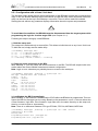
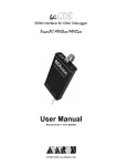
2.1 Connecting the BDI2000 to Target
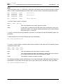
The cable to the target system is a 16 pin flat ribbon cable. In case where the target system has an
appropriate connector, the cable can be directly connected. The pin assignment is in accordance with
the PowerPC COP connector specification.
!
In order to ensure reliable operation of the BDI (EMC, runtimes, etc.) the target cable length must not
exceed 20 cm (8").
Target System
1
PPC
15
COP/JTAG Connector
16
2
BDI2000
BDI
TRGT MODE
TARGET A
15
TARGET B
16
1
2
The green LED «TRGT» marked light up when target is powered up
1 - TDO
2 - QACK
3 - TDI
4 - TRST
5 - HALTED
6 - Vcc Target
7 - TCK
8 - RXD
9 - TMS
10 - TXD
11 - SRESET
12 - GROUND
13 - HRESET
14 - NC (key)
15 - CKSTP_OUT
16 - GROUND
If possible, connect the RXD/TXD pins of a not used SMC, SCC or any UART channel to the COP/
JTAG connector. This two optional signals can be used by the BDI2000 to establish a TCP/IP connection between the host and this target serial I/O port.
Additional Signals:
Pin
Name
Describtion
8
RXD
Serial Data Input
This output of the BDI2000 connects to the RXD pin of a SMC, SCC channel.
10
TXD
Serial Data Output
This input to the BDI2000 connects to the TXD pin of a SMC, SCC channel.
Warning:
Do not use a V24 (RS232) driver when connecting this pins, use target logic levels (Vdd I/O).
© Copyright 1997-2015 by ABATRON AG Switzerland
V 1.31
bdiGDB for BDI2000 (PowerPC 6xx/7xx/82xx/83xx/7400/7410)
User Manual
6
BDI TARGET B Connector Signals:
Pin
Name
Description
1
TDO
JTAG Test Data Out
This input to the BDI2000 connects to the target TDO pin.
2
QACK
QACK
This output of the BDI2000 connects to the target QACK pin. By default this pin is not driven
by the BDI2000. With an entry in the configuration file it can be forced low.
3
TDI
JTAG Test Data In
This output of the BDI2000 connects to the target TDI pin.
4
TRST
JTAG Test Reset
This output of the BDI2000 resets the JTAG TAP controller on the target.
5
IN0
General purpose Input
This input to the BDI2000 connects to the target HALTED pin. Currently not used.
6
Vcc Target
1.8 – 5.0V:
This is the target reference voltage. It indicates that the target has power and it is also used
to create the logic-level reference for the input comparators. It also controls the output logic
levels to the target. It is normally connected to Vdd I/O on the target board.
3.0 – 5.0V with Rev. B :
This input to the BDI2000 is used to detect if the target is powered up. If there is a current
limiting resistor between this pin and the target Vdd, it should be 100 Ohm or less.
7
TCK
JTAG Test Clock
This output of the BDI2000 connects to the target TCK pin.
8
RXD
Serial Data Input (Optional)
This output of the BDI2000 connects to the RXD pin of a SMC, SCC or any other UART
channel.
9
TMS
JTAG Test Mode Select
This output of the BDI2000 connects to the target TMS line.
10
TXD
Serial Data Output (Optional)
This input to the BDI2000 connects to the TXD pin of a SMC, SCC or any other UART channel.
11
SRESET
Soft-Reset
This open collector output of the BDI2000 connects to the target SRESET pin.
12
GROUND
System Ground
13
HRESET
Hard-Reset
This open collector output of the BDI2000 connects to the target HRESET pin.
14
<reseved>
15
IN1
General purpose Input
This input to the BDI2000 connects to the target CKSTP_OUT pin. Currently not used.
16
GROUND
System Ground
© Copyright 1997-2015 by ABATRON AG Switzerland
V 1.31
bdiGDB for BDI2000 (PowerPC 6xx/7xx/82xx/83xx/7400/7410)
User Manual
7
2.1.1 Changing Target Processor Type
Before you can use the BDI2000 with an other target processor type (e.g. CPU32 <--> PPC), a new
setup has to be done (see chapter 2.5). During this process the target cable must be disconnected
from the target system. The BDI2000 needs to be supplied with 5 Volts via the BDI OPTION connector (Version A) or via the POWER connector (Version B). For more information see chapter 2.2.1
«External Power Supply».
!
To avoid data line conflicts, the BDI2000 must be disconnected from the target system while
programming the logic for an other target CPU.
© Copyright 1997-2015 by ABATRON AG Switzerland
V 1.31
bdiGDB for BDI2000 (PowerPC 6xx/7xx/82xx/83xx/7400/7410)
User Manual
8
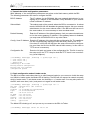
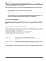
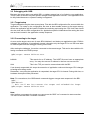
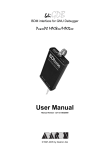
2.2 Connecting the BDI2000 to Power Supply
The BDI2000 needs to be supplied with 5 Volts (max. 1A) via the POWER connector. The available
power supply from Abatron (option) or the enclosed power cable can be directly connected. In order
to ensure reliable operation of the BDI2000, keep the power supply cable as short as possible.
!
For error-free operation, the power supply to the BDI2000 must be between 4.75V and 5.25V DC.
The maximal tolerable supply voltage is 5.25 VDC. Any higher voltage or a wrong polarity
might destroy the electronics.
Rev. B Version
GND 3
1 Vcc
2
4
RS232
BDI
TRGT MODE
POWER
Connector
POWER
LI
TARGET A
TX RX
10 BASE-T
1 - Vcc (+5V)
2 - VccTGT
3 - GROUND
4 - NOT USED
TARGET B
The green LED «BDI» marked light up when 5V power is connected to the BDI2000
Please switch on the system in the following sequence:
• 1 --> external power supply
• 2 --> target system
© Copyright 1997-2015 by ABATRON AG Switzerland
V 1.31
bdiGDB for BDI2000 (PowerPC 6xx/7xx/82xx/83xx/7400/7410)
User Manual
9
2.3 Status LED «MODE»
The built in LED indicates the following BDI states:
BDI
TRGT MODE
TARGET A
MODE LED
TARGET B
BDI STATES
OFF
The BDI is ready for use, the firmware is already loaded.
ON
The power supply for the BDI2000 is < 4.75VDC.
BLINK
The BDI «loader mode» is active (an invalid firmware is loaded or loading firmware is active).
© Copyright 1997-2015 by ABATRON AG Switzerland
V 1.31
bdiGDB for BDI2000 (PowerPC 6xx/7xx/82xx/83xx/7400/7410)
User Manual
10
2.4 Connecting the BDI2000 to Host
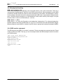
2.4.1 Serial line communication
Serial line communication is only used for the initial configuration of the bdiGDB system.
The host is connected to the BDI through the serial interface (COM1...COM4). The communication
cable (included) between BDI and Host is a serial cable. There is the same connector pinout for the
BDI and for the Host side (Refer to Figure below).
RS232 Connector
(for PC host)
Target System
12345
PPC
1 - NC
2 - RXD data from host
3 - TXD data to host
4 - NC
5 - GROUND
6 - NC
7 - NC
8 - NC
9 - NC
6789
RS232
POWER
LI
TX RX
10 BASE-T
BDI2000
Host
RS232
© Copyright 1997-2015 by ABATRON AG Switzerland
V 1.31
bdiGDB for BDI2000 (PowerPC 6xx/7xx/82xx/83xx/7400/7410)
User Manual
11
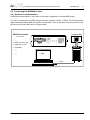
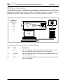
2.4.2 Ethernet communication
The BDI2000 has a built-in 10 BASE-T Ethernet interface (see figure below). Connect an UTP (Unshilded Twisted Pair) cable to the BD2000. For thin Ethernet coaxial networks you can connect a
commercially available media converter (BNC-->10 BASE-T) between your network and the
BDI2000. Contact your network administrator if you have questions about the network.
Target System
10 BASE-T
Connector
1 - TD+
2 - TD3 - RD+
4 - NC
5 - NC
6 - RD7 - NC
8 - NC
1
RS232
POWER
LI
TX RX
8
PPC
10 BASE-T
BDI2000
PC / Unix
Host
Ethernet (10 BASE-T)
The following explains the meanings of the built-in LED lights:
LED
Name
Description
LI
Link
When this LED light is ON, data link is successful between the UTP
port of the BDI2000 and the hub to which it is connected.
TX
Transmit
When this LED light BLINKS, data is being transmitted through the UTP
port of the BDI2000
RX
Receive
When this LED light BLINKS, data is being received through the UTP
port of the BDI2000
© Copyright 1997-2015 by ABATRON AG Switzerland
V 1.31
bdiGDB for BDI2000 (PowerPC 6xx/7xx/82xx/83xx/7400/7410)
User Manual
12
2.5 Initial configuration of the bdiGDB system
On the enclosed diskette you will find the BDI configuration software and the firmware / logic required
for the BDI2000. For Windows users there is also a TFTP server included.
The following files are on the diskette.
b20copgd.exe
Configuration program
b20copgd.xxx
Firmware for the BDI2000
copjed20.xxx
JEDEC file for the BDI2000 (Rev. B) logic device when working with a COP target
copjed21.xxx
JEDEC file for the BDI2000 (Rev. C) logic device when working with a COP target
tftpsrv.exe
TFTP server for Windows (WIN32 console application)
*.cfg
Configuration files
*.def
Register definition files
bdisetup.zip
ZIP Archive with the Setup Tool sources for Linux / UNIX hosts.
Overview of an installation / configuration process:
• Create a new directory on your hard disk
• Copy the entire contents of the enclosed diskette into this directory
• Linux only: extract the setup tool sources and build the setup tool
• Use the setup tool to load/update the BDI firmware/logic
Note: A new BDI has no firmware/logic loaded.
• Use the setup tool to transmit the initial configuration parameters
- IP address of the BDI.
- IP address of the host with the configuration file.
- Name of the configuration file. This file is accessed via TFTP.
- Optional network parameters (subnet mask, default gateway).
Activating BOOTP:
The BDI can get the network configuration and the name of the configuration file also via BOOTP.
For this simple enter 0.0.0.0 as the BDI’s IP address (see following chapters). If present, the subnet
mask and the default gateway (router) is taken from the BOOTP vendor-specific field as defined in
RFC 1533.
With the Linux setup tool, simply use the default parameters for the -c option:
[root@LINUX_1 bdisetup]# ./bdisetup -c -p/dev/ttyS0 -b57
The MAC address is derived from the serial number as follows:
MAC: 00-0C-01-xx-xx-xx , replace the xx-xx-xx with the 6 left digits of the serial number
Example: SN# 93123457 ==>> 00-0C-01-93-12-34
© Copyright 1997-2015 by ABATRON AG Switzerland
V 1.31
bdiGDB for BDI2000 (PowerPC 6xx/7xx/82xx/83xx/7400/7410)
User Manual
13
2.5.1 Configuration with a Linux / Unix host
The firmware / logic update and the initial configuration of the BDI2000 is done with a command line
utility. In the ZIP Archive bdisetup.zip are all sources to build this utility. More information about this
utility can be found at the top in the bdisetup.c source file. There is also a make file included.
Starting the tool without any parameter displays information about the syntax and parameters.
!
To avoid data line conflicts, the BDI2000 must be disconnected from the target system while
programming the logic for an other target CPU (see Chapter 2.1.1).
Following the steps to bring-up a new BDI2000:
1. Build the setup tool:
The setup tool is delivered only as source files. This allows to build the tool on any Linux / Unix host.
To build the tool, simply start the make utility.
[root@LINUX_1 bdisetup]# make
cc -O2
-c -o bdisetup.o bdisetup.c
cc -O2
-c -o bdicnf.o bdicnf.c
cc -O2
-c -o bdidll.o bdidll.c
cc -s bdisetup.o bdicnf.o bdidll.o -o bdisetup
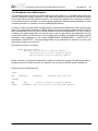
2. Check the serial connection to the BDI:
With "bdisetup -v" you may check the serial connection to the BDI. The BDI will respond with information about the current loaded firmware and network configuration.
Note: Login as root, otherwise you probably have no access to the serial port.
[root@LINUX_1 bdisetup]# ./bdisetup -v -p/dev/ttyS0 -b57
BDI Type : BDI2000 Rev.C (SN: 92152150)
Loader
: V1.05
Firmware : unknown
Logic
: unknown
MAC
: 00-0c-01-92-15-21
IP Addr : 255.255.255.255
Subnet
: 255.255.255.255
Gateway : 255.255.255.255
Host IP : 255.255.255.255
Config
: ??????????????????
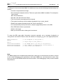
3. Load/Update the BDI firmware/logic:
With "bdisetup -u" the firmware is loaded and the CPLD within the BDI2000 is programmed. This configures the BDI for the target you are using. Based on the parameters -a and -t, the tool selects the
correct firmware / logic files. If the firmware / logic files are in the same directory as the setup tool,
there is no need to enter a -d parameter.
Note: There is no difference between CPU type PPC600, PPC700, MPC8200, MPC7400.
[root@LINUX_1 bdisetup]# ./bdisetup -u -p/dev/ttyS0 -b57 -aGDB -tPPC700
Connecting to BDI loader
Erasing CPLD
Programming firmware with ./b20copgd.108
Programming CPLD with ./copjed21.102
© Copyright 1997-2015 by ABATRON AG Switzerland
V 1.31
bdiGDB for BDI2000 (PowerPC 6xx/7xx/82xx/83xx/7400/7410)
User Manual
14
4. Transmit the initial configuration parameters:
With "bdisetup -c" the configuration parameters are written to the flash memory within the BDI.
The following parameters are used to configure the BDI:
BDI IP Address
The IP address for the BDI2000. Ask your network administrator for assigning an IP address to this BDI2000. Every BDI2000 in your network
needs a different IP address.
Subnet Mask
The subnet mask of the network where the BDI is connected to. A subnet
mask of 255.255.255.255 disables the gateway feature. Ask your network
administrator for the correct subnet mask. If the BDI and the host are in
the same subnet, it is not necessary to enter a subnet mask.
Default Gateway
Enter the IP address of the default gateway. Ask your network administrator for the correct gateway IP address. If the gateway feature is disabled,
you may enter 255.255.255.255 or any other value.
Config - Host IP Address Enter the IP address of the host with the configuration file. The configuration file is automatically read by the BDI after every start-up via TFTP.
If the host IP is 255.255.255.255 then the setup tool stores the configuration read from the file into the BDI internal flash memory. In this case no
TFTP server is necessary.
Configuration file
Enter the full path and name of the configuration file. This file is read by
the setup tool or via TFTP. Keep in mind that TFTP has it’s own root directory (usual /tftpboot).
[root@LINUX_1 bdisetup]# ./bdisetup -c -p/dev/ttyS0 -b57 \
> -i151.120.25.101 \
> -h151.120.25.118 \
> -fppc750.cnf
Connecting to BDI loader
Writing network configuration
Writing init list and mode
Configuration passed
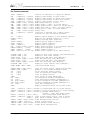
5. Check configuration and exit loader mode:
The BDI is in loader mode when there is no valid firmware loaded or you connect to it with the setup
tool. While in loader mode, the Mode LED is flashing. The BDI will not respond to network requests
while in loader mode. To exit loader mode, the "bdisetup -v -s" can be used. You may also power-off
the BDI, wait some time (1min.) and power-on it again to exit loader mode.
[root@LINUX_1 bdisetup]# ./bdisetup -v -p/dev/ttyS0 -b57 -s
BDI Type : BDI2000 Rev.C (SN: 92152150)
Loader
: V1.05
Firmware : V1.08 bdiGDB for PPC6xx/PPC7xx
Logic
: V1.02 PPC6xx/PPC7xx
MAC
: 00-0c-01-92-15-21
IP Addr : 151.120.25.101
Subnet
: 255.255.255.255
Gateway : 255.255.255.255
Host IP : 151.120.25.118
Config
: ppc750.cnf
The Mode LED should go off, and you can try to connect to the BDI via Telnet.
[root@LINUX_1 bdisetup]# telnet 151.120.25.101
© Copyright 1997-2015 by ABATRON AG Switzerland
V 1.31
bdiGDB for BDI2000 (PowerPC 6xx/7xx/82xx/83xx/7400/7410)
User Manual
15
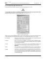
2.5.2 Configuration with a Windows host
First make sure that the BDI is properly connected (see Chapter 2.1 to 2.4).
!
To avoid data line conflicts, the BDI2000 must be disconnected from the target system while
programming the logic for an other target CPU (see Chapter 2.1.1).
dialog box «BDI2000 Update/Setup»
Before you can use the BDI2000 together with the GNU debugger, you must store the initial configuration parameters in the BDI2000 flash memory. The following options allow you to do this:
Port / Speed
Select the communication port and baudrate used to communicate with
the BDI2000 loader during this setup session.
Connect
Click on this button to establish a connection with the BDI2000 loader.
Once connected, the BDI2000 remains in loader mode until it is restarted
or this dialog box is closed.
Current
Press this button to read back the current loaded BDI2000 software and
logic versions. The current loader, firmware and logic version will be
displayed.
Erase
Press this button to erase the BDI2000 flash memory / programmable logic contents. For a normal update it is not necessary to use this function.
Update
This button is only active if there is a newer firmware or logic version present in the execution directory of the bdiGDB setup software. Press this button to write the new firmware and/or logic into the BDI2000 flash memory
/ programmable logic.
© Copyright 1997-2015 by ABATRON AG Switzerland
V 1.31
bdiGDB for BDI2000 (PowerPC 6xx/7xx/82xx/83xx/7400/7410)
User Manual
16
BDI IP Address
Enter the IP address for the BDI2000. Use the following format:
xxx.xxx.xxx.xxx e.g.151.120.25.101
Ask your network administrator for assigning an IP address to this
BDI2000. Every BDI2000 in your network needs a different IP address.
Subnet Mask
Enter the subnet mask of the network where the BDI is connected to.
Use the following format: xxx.xxx.xxx.xxxe.g.255.255.255.0
A subnet mask of 255.255.255.255 disables the gateway feature.
Ask your network administrator for the correct subnet mask.
Default Gateway
Enter the IP address of the default gateway. Ask your network administrator for the correct gateway IP address. If the gateway feature is disabled,
you may enter 255.255.255.255 or any other value..
Config - Host IP Address Enter the IP address of the host with the configuration file. The configuration file is automatically read by the BDI after every start-up via TFTP.
If the host IP is 255.255.255.255 then the setup tool stores the configuration read from the file into the BDI internal flash memory. In this case no
TFTP server is necessary.
Configuration file
Enter the full path and name of the configuration file. This file is read by
the setup tool or via TFTP.
Transmit
Click on this button to store the configuration in the BDI2000 flash
memory.
2.5.3 Recover procedure
In rare instances you may not be able to load the firmware in spite of a correctly connected BDI (error
of the previous firmware in the flash memory). Before carrying out the following procedure, check
the possibilities in Appendix «Troubleshooting». In case you do not have any success with the
tips there, do the following:
• Switch OFF the power supply for the BDI and open the unit as
described in Appendix «Maintenance»
• Place the jumper in the «INIT MODE» position
• Connect the power cable or target cable if the BDI is powered
from target system
• Switch ON the power supply for the BDI again and wait until the
LED «MODE» blinks fast
INIT MODE
• Turn the power supply OFF again
DEFAULT
• Return the jumper to the «DEFAULT» position
• Reassemble the unit as described in Appendix «Maintenance»
© Copyright 1997-2015 by ABATRON AG Switzerland
V 1.31
bdiGDB for BDI2000 (PowerPC 6xx/7xx/82xx/83xx/7400/7410)
User Manual
17
2.6 Testing the BDI2000 to host connection
After the initial setup is done, you can test the communication between the host and the BDI2000.
There is no need for a target configuration file and no TFTP server is needed on the host.
• If not already done, connect the BDI2000 system to the network.
• Power-up the BDI2000.
• Start a Telnet client on the host and connect to the BDI2000 (the IP address you entered during initial configuration).
• If everything is okay, a sign on message like «BDI Debugger for Embedded PowerPC» and
a list of the available commands should be displayed in the Telnet window.
2.7 TFTP server for Windows
The bdiGDB system uses TFTP to access the configuration file and to load the application program.
Because there is no TFTP server bundled with Windows, Abatron provides a TFTP server application
tftpsrv.exe. This WIN32 console application runs as normal user application (not as a system service).
Command line syntax:
tftpsrv [p] [w] [dRootDirectory]
Without any parameter, the server starts in read-only mode. This means, only read access request
from the client are granted. This is the normal working mode. The bdiGDB system needs only read
access to the configuration and program files.
The parameter [p] enables protocol output to the console window. Try it.
The parameter [w] enables write accesses to the host file system.
The parameter [d] allows to define a root directory.
tftpsrv p
Starts the TFTP server and enables protocol output
tftpsrv p w
Starts the TFTP server, enables protocol output and write accesses are
allowed.
tftpsrv dC:\tftp\
Starts the TFTP server and allows only access to files in C:\tftp and its
subdirectories. As file name, use relative names.
For example "bdi\mpc750.cfg" accesses "C:\tftp\bdi\mpc750.cfg"
You may enter the TFTP server into the Startup group so the server is started every time you login.
© Copyright 1997-2015 by ABATRON AG Switzerland
V 1.31
bdiGDB for BDI2000 (PowerPC 6xx/7xx/82xx/83xx/7400/7410)
User Manual
18
3 Using bdiGDB
3.1 Principle of operation
The firmware within the BDI handles the GDB request and accesses the target memory or registers
via the JTAG interface. There is no need for any debug software on the target system. After loading
the code via TFTP, debugging can begin at the very first assembler statement.
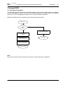
Whenever the BDI system is powered-up the following sequence starts:
Power On
initial
configuration
valid?
no
yes
activate BDI2000 loader
Get configuration file
via TFTP
Reset System and
Process target init list
Power OFF
Process GDB requests
Process Telnet commands
Power OFF
Note:
During every restart of the processor the instruction cache will be flash invalidated.
© Copyright 1997-2015 by ABATRON AG Switzerland
V 1.31
bdiGDB for BDI2000 (PowerPC 6xx/7xx/82xx/83xx/7400/7410)
User Manual
19
3.2 Configuration File
The configuration file is automatically read by the BDI after every power on.
The syntax of this file is as follows:
; comment
[part name]
identifier parameter1
identifier parameter1
.....
[part name]
identifier parameter1
identifier parameter1
.....
etc.
parameter2 ..... parameterN
parameter2 ..... parameterN
; comment
parameter2 ..... parameterN
parameter2 ..... parameterN
Numeric parameters can be entered as decimal (e.g. 700) or as hexadecimal (0x80000).
3.2.1 Part [INIT]
The part [INIT] defines a list of commands which should be executed every time the target comes out
of reset. The commands are used to get the target ready for loading the program file.
WGPR register value
Write value to the selected general purpose register.
register
the register number 0 .. 31
value
the value to write into the register
Example: WGPR 0 5
WSPR register value
Write value to the selected special purpose register.
register
the register number
value
the value to write into the register
Example: WSPR 27 0x00001002 ; SRR1 : ME,RI
WSR register value
Write value to the selected segment register.
register
the register number
value
the value to write into the register
Example: WSR 0 0x00001002 ; SR0
WREG name value
Write value to the selected register/memory by name
name
the case sensitive register name from the reg def file
value
the value to write to the register/memory
Example: WREG pc 0x00001000
DELAY value
Delay for the selected time. A delay may be necessary to let the clock PLL
lock again after a new clock rate is selected.
value
the delay time in milliseconds (1...30000)
Example: DELAY 500 ; delay for 0.5 seconds
© Copyright 1997-2015 by ABATRON AG Switzerland
V 1.31
bdiGDB for BDI2000 (PowerPC 6xx/7xx/82xx/83xx/7400/7410)
User Manual
20
WM8 address value
Write a byte (8bit) to the selected memory place.
address
the memory address
value
the value to write to the target memory
Example: WM8 0xFFFFFA21 0x04 ; SYPCR: watchdog disable ...
WM16 address value
Write a half word (16bit) to the selected memory place.
address
the memory address
value
the value to write to the target memory
Example: WM16 0x02200200 0x0002 ; TBSCR
WM32 address value
Write a word (32bit) to the selected memory place.
address
the memory address
value
the value to write to the target memory
Example: WM32 0x02200000 0x01632440 ; SIUMCR
WM64 address value
Write a double word (64bit) to the selected memory place. This entry is
mainly used to unlock flash blocks. The pattern written is generated by duplicating the value (0x12345678 -> 0x1234567812345678).
address
the memory address
value
the value used to generate the pattern
Example: WM64 0xFFF00000 0x00600060 ; unlock block 0
RM8 address value
Read a byte (8bit) from the selected memory place.
address
the memory address
Example: RM8 0x00000000
RM16 address value
Read a half word (16bit) from the selected memory place.
address
the memory address
Example: RM16 0x00000000
RM32 address value
Read a word (32bit) from the selected memory place.
address
the memory address
Example: RM32 0x00000000
RM64 address value
Read a double word (64bit) from the selected memory place.
address
the memory address
Example: RM64 0x00000000
SUPM memaddr mdraddr Starts a sequence of writes to the UPM RAM array (MPC82xx).
memaddr
an address in the UPM memory range
dataaddr
the address of the MDR register
Example:
WM32 0x04710118 0x10000081 ; BR3
WM32 0x04710170 0x10000000 ; MAMR setup
SUPM 0x10000000 0x04710188
WUPM dummy data
Write to the UPM RAM array (*mdraddr = data, *memaddr = 0).
dummy
this value is not used here (use 0)
data
this value is written to the UPM data register
Example:
WUPM 0 0x0FFFEC04
© Copyright 1997-2015 by ABATRON AG Switzerland
V 1.31
bdiGDB for BDI2000 (PowerPC 6xx/7xx/82xx/83xx/7400/7410)
User Manual
21
TSZ1 start end
Defines a memory range with 1 byte maximal transfer size.
Normally when the BDI reads or writes a memory block, it tries to access
the memory with a transfer size of 8 bytes. The TSZx entry allows to define
a maximal transfer size for up to 8 address ranges.
start
the start address of the memory range
end
the end address of the memory range
Example: TSZ1 0xFF000000 0xFFFFFFFF ; PCI ROM space
TSZ2 start end
Defines a memory range with 2 byte maximal transfer size.
TSZ4 start end
Defines a memory range with 4 byte maximal transfer size.
MMAP start end
Because a memory access to an invalid memory space via JTAG can lead
to a deadlock, this entry can be used to define up to 32 valid memory ranges. If at least one memory range is defined, the BDI checks against this
range(s) and avoids accessing of not mapped memory ranges.
start
the start address of a valid memory range
end
the end address of this memory range
Example: MMAP 0xFFE00000 0xFFFFFFFF ;Boot ROM
Example how to write to the UPM array:
WM32
WM32
WM32
SUPM
WUPM
WUPM
WUPM
WUPM
WUPM
WUPM
WUPM
WUPM
WUPM
WUPM
WUPM
WM32
0x0471011C
0x04710118
0x04710170
0x10000000
0x00000000
0x00000000
0x00000000
0x00000000
0x00000000
...
0x00000000
0x00000000
0x00000000
0x00000000
0x00000000
0x00000000
0x04710170
0xFF000000
0x10000081
0x10000000
0x04710188
0xaba00000
0xaba00001
0xaba00002
0xaba00003
0xaba00004
0xaba0003A
0xaba0003B
0xaba0003C
0xaba0003D
0xaba0003E
0xaba0003F
0x00000000
;OR3
;BR3
;MAMR : setup for array write
;set address of UPM range and MDR
;write UPM array
;MAMR : setup for normal mode
© Copyright 1997-2015 by ABATRON AG Switzerland
V 1.31
bdiGDB for BDI2000 (PowerPC 6xx/7xx/82xx/83xx/7400/7410)
User Manual
22
3.2.2 Part [TARGET]
The part [TARGET] defines some target specific values.
CPUTYPE type [32BIT]
This value gives the BDI information about the connected CPU. The optional second parameter (32BIT) defines that the PPC core works in 32-bit
data bus mode. For I/O voltage support see note below.
type
750, 750CX, 750FX, 750GX, 750CL, 7400, 7410,
5121, 5200, 8240, 8260, 8280, 8275, 8270, 8220,
8300, 8343, 8347, 8349, 8358, 8360, 8321, 8323,
8313, 8314, 8315, 8377, 8378, 8379
Example:
CPUTYPE 8260
ENDIAN format
This entry defines the endiannes of the memory system. Little endian is
only supported for the MPC83xx processors (True Little Endian).
format
The endiannes of the target memory:
BIG (default), LITTLE
Example:
ENDIAN LITTLE
JTAGCLOCK value
With this value you select the JTAG clock frequency.
value
The JTAG clock frequency in Hertz or an index value
from the following table:
0 = 16 MHz
1 = 8 MHz
2 = 4 MHz
Example:
JTAGCLOCK 1 ; JTAG clock is 8 MHz
BDIMODE mode [RUN]
This parameter selects the BDI debugging mode. The following modes are
supported:
LOADONLY Loads and starts the application code. No debugging via
JTAG port.
AGENT
The debug agent runs within the BDI. There is no need
for any debug software on the target. This mode accepts
a second parameter. If RUN is entered as a second parameter, the loaded application will be started immediately, otherwise only the PC is set and BDI waits for
GDB requests.
Example:
BDIMODE AGENT RUN
STARTUP mode [runtime]This parameter selects the target startup mode. The following modes are
supported:
RESET
This default mode forces the target to debug mode immediately out of reset. No code is executed after reset.
STOP
In this mode, the BDI lets the target execute code for
"runtime" milliseconds after reset. This mode is useful
when monitor code should initialize the target system.
RUN
After reset, the target executes code until stopped by the
Telnet "halt" command.
Example:
STARTUP STOP 3000 ; let the CPU run for 3 seconds
© Copyright 1997-2015 by ABATRON AG Switzerland
V 1.31
bdiGDB for BDI2000 (PowerPC 6xx/7xx/82xx/83xx/7400/7410)
User Manual
23
BOOTADDR address
Normally the boot address for PowerPC is 0xFFF00100. The MPC8260
allows also to boot from 0x00000100. The BDI sets a hardware breakpoint
at this address to freeze the processor immediately out of reset.
address
the address where to set the startup breakpoint
Example:
BOOTADDR 0x00000100
WORKSPACE address
If a workspace is defined, the BDI uses a faster download mode. The
workspace is used for a short code sequence. There must be at least 256
Bytes of RAM available for this purpose. The BDI also uses this workspace for a code sequence to flush the data cache and to access L2 private memory. See also DCACHE and L2PM configuration parameter.
address
the address of the RAM area
Example:
WORKSPACE 0x00000000
BREAKMODE mode
This parameter defines how breakpoints are implemented. The current
mode can also be changed via the Telnet interface
SOFT
This is the normal mode. Breakpoints are implemented
by replacing code with a TRAP or ILLEGAL instruction.
HARD
In this mode, the PPC breakpoint hardware is used.
Only 1 or 2 breakpoints at a time is supported.
Example:
BREAKMODE HARD
STEPMODE mode
This parameter defines how single step (instruction step) is implemented.
The alternate step mode (HWBP) may be useful when stepping instructions that causes a TLB miss exception.
TRACE
This is the default mode. Single step is implemented by
setting the SE bit in MSR.
HWBP
In this mode, a hardware breakpoint on the next instruction is used to implement single stepping.
Example:
STEPMODE HWBP
VECTOR CATCH
When this line is present, the BDI catches all unhandled exceptions.
Catching exceptions is only possible if the memory at address
0x00000000 to 0x00001FFF is writable.
Example:
VECTOR CATCH ; catch unhandled exception
© Copyright 1997-2015 by ABATRON AG Switzerland
V 1.31
bdiGDB for BDI2000 (PowerPC 6xx/7xx/82xx/83xx/7400/7410)
DCACHE mode
User Manual
24
This parameter defines if the BDI flushes the data cache before it accesses memory. If the BDI does not flush the data cache, it executes L1 cache
coherent memory accesses. If the L1 data cache is enabled and the appropriate data is valid in the cache, data is read from the cache. For a write
access, the cache is updated and the data also written to external memory. If there is an enabled L2 cache, flushing the data cache is recommended except for 750FX/GX. Otherwise the debugger may display wrong data
and working with software breakpoints may also fail. The following modes
are supported:
NOFLUSH
The data cache is not flushed. L1 cache coherent memory accesses are used. Recommended if there is no L2
cache in the system or the target is 750FX/GX.
FLUSH
Before the BDI accesses any memory, the data cache is
flushed and only external memory is accessed. This
mode needs a valid workspace for the flush code.
Example:
DCACHE NOFLUSH ; do not flush data cache
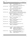
POWERUP delay [NORESET]
The value entered in this configuration line is the delay time in milliseconds
the BDI waits before it begins the reset sequence. This time should be longer than the on-board reset circuit asserts HRESET (default is 5 seconds).
If the NORESET option is not present (default), the BDI asserts the
HRESET signal via the debug connector as soon as power-up is detected.
delay
the power-up start delay in milliseconds
Example:
POWERUP 5000
;start delay after power-up
WAKEUP time
This entry in the init list allows to define a delay time (in ms) the BDI inserts
between releasing the COP-HRESET line and starting communicating
with the target. This init list entry may be necessary if COP-HRESET is delayed on its way to the PowerPC reset pin.
time
the delay time in milliseconds
Example:
WAKEUP 3000 ; insert 3sec wake-up time
MEMDELAY clocks
For slow memory it may be necessary to increase the number of clocks
used to execute a memory access cycle. If for example you cannot access
boot ROM content with the default configuration of your memory controller, define additional memory access clocks.
clocks
additional number of CPU clocks for a memory access
Example:
MEMDELAY 2000 ; additional memory access clocks
L2PM base size
Defines the base address and size of the L2 cache private memory. Because L2 cache private memory cannot be accessed directly via JTAG,
the BDI loads some support code into the workspace and uses it to access
this memory range. Therefore a workspace is necessary to access this
memory range.
Example: L2PM 0x01000000 0x80000 ; define 512k L2 private memory
© Copyright 1997-2015 by ABATRON AG Switzerland
V 1.31
bdiGDB for BDI2000 (PowerPC 6xx/7xx/82xx/83xx/7400/7410)
User Manual
25
MMU XLAT [kb]
In order to support Linux kernel debugging when MMU is on, the BDI
translates effective (virtual) to physical addresses. This translation is done
based on the current MMU configuration (BAT’s and page tables). If this
configuration line is present and address relocation active (MSR bits IR/
DR), the BDI translates the addresses received from GDB before it accesses physical memory. The optional parameter defines the kernel virtual base address (default is 0xC0000000) and is used for default address
translation. For more information see also chapter "Embedded Linux MMU
Support". Addresses entered at the Telnet are never translated. Translation can be probed with the Telnet command PHYS.
kb
The kernel virtual base address (KERNELBASE)
Example:
MMU XLAT ;enable address translation
PTBASE addr
This parameter defines the physical memory address where the BDI looks
for the virtual address of the array with the two page table pointers. For
more information see also chapter "Embedded Linux MMU Support".
addr
Physical address of the memory used to store the virtual
address of the array with the two page table pointers.
Example:
PTBASE 0xf0
PARITY ON
When this line is present, the BDI generates the data write parity bits.
Example:
PARITY ON ; generate data write parity
REGLIST list
With GDB version 5.0, the number of registers read from the target has
been increased. Additional registers like SR’s, BAT’s and SPR’s are requested when you select a specific PowerPC variant with the "set processor" command (see GDB source file rs6000-tdep.c). In order to be
compatible with older GDB versions and to optimize the time spent to read
registers, this parameter can be used. You can define which register group
is really read from the target. By default STD and FPR are read and transferred. This default is compatible with older GDB versions. The following
names are use to select a register group:
STD
The standard (old) register block. The FPR registers are
not read from the target but transferred. You can’t disable this register group.
FPR
The floating point registers are read and transferred.
SR
The segment registers.
BAT
The IBAT and DBAT registers
SPR
The additional special purpose registers
AUX
currently not used
ALL
Include all register groups
Example:
REGLIST STD ; only standard registers
REGLIST STD FPR SPR ; all except SR and BAT
© Copyright 1997-2015 by ABATRON AG Switzerland
V 1.31
bdiGDB for BDI2000 (PowerPC 6xx/7xx/82xx/83xx/7400/7410)
User Manual
26
VIO port [baudrate]
When this line is present and the optional Rx/Tx pins of the COP connector are routed to a UART, the serial IO of this UART can be accessed from
the host via a Telnet session. The port parameter defines the TCP port
used for this BDI to host communication. You may choose any port except
0 and the default Telnet port (23). On the host, open a Telnet session using this port. Now you should see the UART output in this Telnet session.
You can use the normal Telnet connection to the BDI in parallel, they work
completely independent. Also input to the UART is implemented.
Note: You cannot use SIO and VIO at the same time.
port
The TCP/IP port used for the host communication.
baudrate
The BDI supports 2400 ... 115200 baud
Example:
VIO 7 ;TCP port for virtual IO
SIO port [baudrate]
When this line is present, a TCP/IP channel is routed to the BDI’s RS232
connector. The port parameter defines the TCP port used for this BDI to
host communication. You may choose any port except 0 and the default
Telnet port (23). On the host, open a Telnet session using this port. Now
you should see the UART output in this Telnet session. You can use the
normal Telnet connection to the BDI in parallel, they work completely independent. Also input to the UART is implemented.
Note: You cannot use SIO and VIO at the same time.
port
The TCP/IP port used for the host communication.
baudrate
The BDI supports 2400 ... 115200 baud
Example:
SIO 7 9600 ;TCP port for virtual IO
QACK LOW
When this line is present, the BDI forces the QACK pin (pin 2) on the COP
connector low. By default this pin is not driven by the BDI. Maybe useful
for PPC750 and PPC7400 targets.
Example:
QACK LOW ; force QACK low via COP connector
RCW high low
Only for MPC83xx targets:
When this line is present, the BDI overrides the Reset Configuration
Words with the values provided. Provide always both words.
high
The Reset Configuration Word High
low
The Reset Configuration Word Low
Example:
RCW 0x84600000 0x04040000 ; override RCW’s
© Copyright 1997-2015 by ABATRON AG Switzerland
V 1.31
bdiGDB for BDI2000 (PowerPC 6xx/7xx/82xx/83xx/7400/7410)
User Manual
27
Daisy chained JTAG devices:
The BDI can also handle systems with multiple devices connected to the JTAG scan chain. In order
to put the other devices into BYPASS mode and to count for the additional bypass registers, the BDI
needs some information about the scan chain layout. Enter the number (count) and total instruction
register (irlen) length of the devices present before the PowerPC chip (Predecessor). Enter the appropriate information also for the devices following the PowerPC chip (Successor):
SCANPRED count irlen
This value gives the BDI information about JTAG devices present before
the PowerPC chip in the JTAG scan chain.
count
The number of preceding devices (0 ... 31)
irlen
The sum of the length of all preceding instruction registers (IR) (0 ... 1024)
Example:
SCANPRED 1 8 ; one device with an IR length of 8
SCANSUCC count irlen
This value gives the BDI information about JTAG devices present after the
PowerPC chip in the JTAG scan chain.
count
The number of succeeding devices (0 ... 31)
irlen
The sum of the length of all succeeding instruction registers (IR) (0 ... 1024)
Example:
SCANSUCC 2 12 ; two device with an IR length of 8+4
© Copyright 1997-2015 by ABATRON AG Switzerland
V 1.31
bdiGDB for BDI2000 (PowerPC 6xx/7xx/82xx/83xx/7400/7410)
User Manual
28
3.2.3 Part [HOST]
The part [HOST] defines some host specific values.
IP ipaddress
The IP address of the host.
ipaddress
the IP address in the form xxx.xxx.xxx.xxx
Example:
IP 151.120.25.100
FILE filename
The default name of the file that is loaded into RAM using the Telnet ’load’
command. This name is used to access the file via TFTP. If the filename
starts with a $, this $ is replace with the path of the configuration file name.
filename
the filename including the full path or $ for relative path.
Example:
FILE F:\gnu\demo\ppc\test.elf
FILE $test.elf
FORMAT format [offset] The format of the image file and an optional load address offset. If the image is already stored in ROM on the target, select ROM as the format. The
optional parameter "offset" is added to any load address read from the image file.
format
SREC, BIN, AOUT, ELF, IMAGE* or ROM
Example:
FORMAT ELF
FORMAT ELF 0x10000
LOAD mode
In Agent mode, this parameters defines if the code is loaded automatically
after every reset.
mode
AUTO, MANUAL
Example:
LOAD MANUAL
START address
The address where to start the program file. If this value is not defined and
the core is not in ROM, the address is taken from the image file. If this value is not defined and the core is already in ROM, the PC will not be set
before starting the program file. This means, the program starts at the normal reset address (0xFFF00100).
address
the address where to start the program file
Example:
START 0x1000
* Special IMAGE load format:
The IMAGE format is a special version of the ELF format used to load a Linux boot image into target
memory. When this format is selected, the BDI loads not only the loadable segment as defined in the
Program Header, it also loads the rest of the file up to the Section Header Table. The relationship
between load address and file offset will be maintained throughout this process. This way, the compressed Linux image and a optional RAM disk image will also be loaded.
© Copyright 1997-2015 by ABATRON AG Switzerland
V 1.31
bdiGDB for BDI2000 (PowerPC 6xx/7xx/82xx/83xx/7400/7410)
User Manual
29
DEBUGPORT port [RECONNECT]
The TCP port GDB uses to access the target. If the RECONNECT parameter is present, an open TCP/IP connection (Telnet/GDB) will be closed if
there is a connect request from the same host (same IP address).
port
the TCP port number (default = 2001)
Example:
DEBUGPORT 2001
PROMPT string
This entry defines a new Telnet prompt. The current prompt can also be
changed via the Telnet interface.
Example:
PROMPT PPC_2
DUMP filename
The default file name used for the Telnet DUMP command.
filename
the filename including the full path
Example:
DUMP dump.bin
TELNET mode
By default the BDI sends echoes for the received characters and supports
command history and line editing. If it should not send echoes and let the
Telnet client in "line mode", add this entry to the configuration file.
mode
ECHO (default), NOECHO or LINE
Example:
TELNET NOECHO ; use old line mode
© Copyright 1997-2015 by ABATRON AG Switzerland
V 1.31
bdiGDB for BDI2000 (PowerPC 6xx/7xx/82xx/83xx/7400/7410)
User Manual
30
3.2.4 Part [FLASH]
The Telnet interface supports programming and erasing of flash memories. The bdiGDB system has
to know which type of flash is used, how the chip(s) are connected to the CPU and which sectors to
erase in case the ERASE command is entered without any parameter.
CHIPTYPE type
This parameter defines the type of flash used. It is used to select the correct programming algorithm.
format
AM29F, AM29BX8, AM29BX16, I28BX8, I28BX16,
AT49, AT49X8, AT49X16, STRATAX8, STRATAX16,
MIRROR, MIRRORX8, MIRRORX16,
S29M32X16, S29GLSX16, S29WSRX16, S29VSRX16
M58X32, AM29DX16, AM29DX32
Example:
CHIPTYPE AM29F
CHIPSIZE size
The size of one flash chip in bytes (e.g. AM29F010 = 0x20000). This value
is used to calculate the starting address of the current flash memory bank.
size
the size of one flash chip in bytes
Example:
CHIPSIZE 0x80000
BUSWIDTH width
Enter the width of the memory bus that leads to the flash chips. Do not enter the width of the flash chip itself. The parameter CHIPTYPE carries the
information about the number of data lines connected to one flash chip.
For example, enter 16 if you are using two AM29F010 to build a 16bit flash
memory bank.
with
the width of the flash memory bus in bits (8 | 16 | 32 | 64)
Example:
BUSWIDTH 16
FILE filename
The default name of the file that is programmed into flash using the Telnet
’prog’ command. This name is used to access the file via TFTP. If the filename starts with a $, this $ is replace with the path of the configuration file
name. This name may be overridden interactively at the Telnet interface.
filename
the filename including the full path or $ for relative path.
Example:
FILE F:\gnu\ppc\bootrom.hex
FILE $bootrom.hex
FORMAT format [offset] The format of the file and an optional address offset. The optional parameter "offset" is added to any load address read from the program file.
You get the best programming performance when using a binary format
(BIN, AOUT, ELF or IMAGE).
format
SREC, BIN, AOUT, ELF or IMAGE
Example:
FORMAT BIN 0x10000
WORKSPACE address
If a workspace is defined, the BDI uses a faster programming algorithm
that runs out of RAM on the target system. Otherwise, the algorithm is processed within the BDI. The workspace is used for a 1kByte data buffer and
to store the algorithm code. There must be at least 2kBytes of RAM available for this purpose.
address
the address of the RAM area
Example:
WORKSPACE 0x00000000
© Copyright 1997-2015 by ABATRON AG Switzerland
V 1.31
bdiGDB for BDI2000 (PowerPC 6xx/7xx/82xx/83xx/7400/7410)
User Manual
31
ERASE addr [increment count] [mode [wait]]
The flash memory may be individually erased or unlocked via the Telnet
interface. In order to make erasing of multiple flash sectors easier, you can
enter an erase list. All entries in the erase list will be processed if you enter
ERASE at the Telnet prompt without any parameter. This list is also used
if you enter UNLOCK at the Telnet without any parameters. With the "increment" and "count" option you can erase multiple equal sized sectors
with one entry in the erase list.
address
Address of the flash sector, block or chip to erase
increment
If present, the address offset to the next flash sector
count
If present, the number of equal sized sectors to erase
mode
BLOCK, CHIP, UNLOCK
Without this optional parameter, the BDI executes a sector erase. If supported by the chip, you can also specify
a block or chip erase. If UNLOCK is defined, this entry is
also part of the unlock list. This unlock list is processed
if the Telnet UNLOCK command is entered without any
parameters.
Note: Chip erase does not work for large chips because
the BDI time-outs after 3 minutes. Use block erase.
wait
The wait time in ms is only used for the unlock mode. After starting the flash unlock, the BDI waits until it processes the next entry.
Example:
ERASE 0xff040000 ;erase sector 4 of flash
ERASE 0xff060000 ;erase sector 6 of flash
ERASE 0xff000000 CHIP ;erase whole chip(s)
ERASE 0xff010000 UNLOCK 100 ;unlock, wait 100ms
ERASE 0xff000000 0x10000 7 ; erase 7 sectors
Example for the ADS8260 flash memory:
[FLASH]
CHIPTYPE
CHIPSIZE
BUSWIDTH
WORKSPACE
FILE
ERASE
ERASE
ERASE
ERASE
I28BX8
;Flash type
0x200000
;The size of one flash chip in bytes (e.g. AM29F010 = 0x20000)
32
;The width of the flash memory bus in bits (8 | 16 | 32 | 64)
0x04700000 ;workspace in dual port RAM
E:\gnu\demo\ads8260\bootrom.hex ;The file to program
0xFF900000 ;erase sector 4 of flash SIMM (LH28F016SCT)
0xFF940000 ;erase sector 5 of flash SIMM
0xFF980000 ;erase sector 6 of flash SIMM
0xFF9c0000 ;erase sector 7 of flash SIMM
the above erase list maybe replaces with:
ERASE
0xFF900000
0x40000
4 ; erase sector 4 to 7 of flash SIMM
© Copyright 1997-2015 by ABATRON AG Switzerland
V 1.31
bdiGDB for BDI2000 (PowerPC 6xx/7xx/82xx/83xx/7400/7410)
User Manual
32
Supported standard parallel NOR Flash Memories:
There are different flash algorithm supported. Almost all currently available parallel NOR flash memories can be programmed with one of these algorithm. The flash type selects the appropriate algorithm and gives additional information about the used flash.
On our web site (www.abatron.ch -> Debugger Support -> GNU Support -> Flash Support) there is a
PDF document available that shows the supported parallel NOR flash memories.
Some newer Spansion MirrorBit flashes cannot be programmed with the MIRRORX16 algorithm because of the used unlock address offset. Use S29M32X16 for these flashes.
The AMD and AT49 algorithm are almost the same. The only difference is, that the AT49 algorithm
does not check for the AMD status bit 5 (Exceeded Timing Limits).
Only the AMD and AT49 algorithm support chip erase. Block erase is only supported with the AT49
algorithm. If the algorithm does not support the selected mode, sector erase is performed. If the chip
does not support the selected mode, erasing will fail. The erase command sequence is different only
in the 6th write cycle. Depending on the selected mode, the following data is written in this cycle (see
also flash data sheets): 0x10 for chip erase, 0x30 for sector erase, 0x50 for block erase.
To speed up programming of Intel Strata Flash and AMD MirrorBit Flash, an additional algorithm is
implemented that makes use of the write buffer. The Strata algorithm needs a workspace, otherwise
the standard Intel algorithm is used.
The Telnet "eprog" command:
The Telnet "eprog" command automatically erases the used sectors based on the information in the
ELF header. Instead of "prog" you have to use the "eprog" command. The BDI needs information
about the sector addresses and sizes of the used flash. It will get it from the erase list in the
configuration file. The syntax is "ERASE address size count". It is not necessary to specify all flash
sectors. But you have to specify those sectors that are candidates for erase/program.
If you use "erase" via Telnet then the whole list will be erased. If you use "eprog" the sectors are
checked against the ELF header and only the relevant sectors will be erased before programming.
This command supports only ELF files. Binary and S-record files are not supported. For all file formats other than ELF, the "eprog" command maps to the normal "prog" command.
© Copyright 1997-2015 by ABATRON AG Switzerland
V 1.31
bdiGDB for BDI2000 (PowerPC 6xx/7xx/82xx/83xx/7400/7410)
User Manual
33
Note:
Some Intel flash chips (e.g. 28F800C3, 28F160C3, 28F320C3) power-up with all blocks in locked
state. In order to erase/program those flash chips, use the init list to unlock the appropriate blocks:
WM16
WM16
WM16
WM16
WM16
0xFFF00000
0xFFF00000
0xFFF10000
0xFFF10000
....
0xFFF00000
0x0060
0x00D0
0x0060
0x00D0
unlock block 0
0xFFFF
select read mode
unlock block 1
or use the Telnet "unlock" command:
UNLOCK [<addr> [<delay>]]
addr
This is the address of the sector (block) to unlock
delay
A delay time in milliseconds the BDI waits after sending the unlock command to the flash. For example, clearing all lock-bits of an Intel J3 Strata
flash takes up to 0.7 seconds.
If "unlock" is used without any parameter, all sectors in the erase list with the UNLOCK option are
processed.
To clear all lock-bits of an Intel J3 Strata flash use for example:
BDI> unlock 0xFF000000 1000
To erase or unlock multiple, continuous flash sectors (blocks) of the same size, the following Telnet
commands can be used:
ERASE <addr> <step> <count>
UNLOCK <addr> <step> <count>
addr
This is the address of the first sector to erase or unlock.
step
This value is added to the last used address in order to get to the next sector. In other words, this is the size of one sector in bytes.
count
The number of sectors to erase or unlock.
The following example unlocks all 256 sectors of an Intel Strata flash (28F256K3) that is mapped to
0x00000000. In case there are two flash chips to get a 32bit system, double the "step" parameter.
BDI> unlock 0x00000000 0x20000 256
© Copyright 1997-2015 by ABATRON AG Switzerland
V 1.31
bdiGDB for BDI2000 (PowerPC 6xx/7xx/82xx/83xx/7400/7410)
User Manual
34
3.2.5 Part [REGS]
In order to make it easier to access target registers via the Telnet interface, the BDI can read in a
register definition file. In this file, the user defines a name for the register and how the BDI should
access it (e.g. as memory mapped, memory mapped with offset, ...). The name of the register definition file and information for different registers type has to be defined in the configuration file. The
register name, type, address/offset/number and size are defined in a separate register definition file.
An entry in the register definition file has the following syntax:
name
type
addr
[size [SWAP]]
name
The name of the register (max. 12 characters)
type
The register type
GPR
SPR
MBAR
MM
DMM1...DMM4
IMM1...IMM4
General purpose register
Special purpose register
Relative to MBAR memory mapped registers.
The BDI knows the current MBAR address for
MPC5200, MPC8220 and MPC83xx targets.
Absolute direct memory mapped register
Relative direct memory mapped register
Indirect memory mapped register
addr
The address, offset or number of the register
size
The size (8, 16, 32) of the register (default is 32)
SWAP
If present, the bytes of a 16bit or 32bit register are swapped. This is useful
to access little endian ordered registers (e.g. MPC8240 configuration registers).
The following entries are supported in the [REGS] part of the configuration file:
FILE filename
The name of the register definition file. This name is used to access the
file via TFTP. If the filename starts with a $, this $ is replace with the path
of the configuration file name. The file is loaded once during BDI startup.
filename
the filename including the full path or $ for relative path.
Example:
FILE C:\bdi\regs\mpc8260.def
DMMn base
This defines the base address of direct memory mapped registers. This
base address is added to the individual offset of the register.
base
the base address
Example:
DMM1 0x01000
IMMn addr data
This defines the addresses of the memory mapped address and data registers of indirect memory mapped registers. The address of a IMMn register is first written to "addr" and then the register value is access using
"data" as address.
addr
the address of the Address register
data
the address of the Data register
Example:
DMM1 0x04700000
Remark:
The registers msr, cr and fpspr are predefined
© Copyright 1997-2015 by ABATRON AG Switzerland
V 1.31
bdiGDB for BDI2000 (PowerPC 6xx/7xx/82xx/83xx/7400/7410)
User Manual
35
Example for a register definition (MPC8260):
Entry in the configuration file:
[REGS]
DMM1
0x04700000
FILE
E:\bdi\mpc8260\reg8260.def
;Internal Memory Map Base Address
;The register definition file
The register definition file:
;name
type
addr
size
;------------------------------------------;
gpr0
GPR
0
sp
GPR
1
;
xer
SPR
1
lr
SPR
8
ctr
SPR
9
sprg0
SPR
272
sprg1
SPR
273
sprg2
SPR
274
sprg3
SPR
275
;
;
; DMM1 must be set to the internal memory map base address
;
siumcr
DMM1
0x10000
32
sypcr
DMM1
0x10004
32
;
br0
DMM1
0x10100
32
or1
DMM1
0x10100
32
;
sicr
DMM1
0x10c00
16
sivec
DMM1
0x10c04
32
Now the defined registers can be accessed by name via the Telnet interface:
BDI> rd sicr
BDI>rm br0 0xFF801801
© Copyright 1997-2015 by ABATRON AG Switzerland
V 1.31
bdiGDB for BDI2000 (PowerPC 6xx/7xx/82xx/83xx/7400/7410)
User Manual
36
3.3 Debugging with GDB
Because the target agent runs within BDI, no debug support has to be linked to your application.
There is also no need for any BDI specific changes in the application sources. Your application must
be fully linked because no dynamic loading is supported.
3.3.1 Target setup
Target initialization may be done at two places. First with the BDI configuration file, second within the
application. The setup in the configuration file must at least enable access to the target memory
where the application will be loaded. Disable the watchdog and setting the CPU clock rate should
also be done with the BDI configuration file. Application specific initializations like setting the timer
rate are best located in the application startup sequence.
3.3.2 Connecting to the target
As soon as the target comes out of reset, BDI initializes it and loads your application code. If RUN is
selected, the application is immediately started, otherwise only the target PC is set. BDI now waits
for GDB request from the debugger running on the host.
After starting the debugger, it must be connected to the remote target. This can be done with the following command at the GDB prompt:
(gdb)target remote bdi2000:2001
bdi2000
This stands for an IP address. The HOST file must have an appropriate
entry. You may also use an IP address in the form xxx.xxx.xxx.xxx
2001
This is the TCP port used to communicate with the BDI
If not already suspended, this stops the execution of application code and the target CPU changes
to background debug mode.
Remember, every time the application is suspended, the target CPU is freezed. During this time, no
hardware interrupts will be processed.
Note: For convenience, the GDB detach command triggers a target reset sequence in the BDI.
(gdb)...
(gdb)detach
... Wait until BDI has resetet the target and reloaded the image
(gdb)target remote bdi2000:2001
Note:
After loading a program to the target you cannot use the GDB "run" command to start execution.
You have to use the GDB "continue" command.
© Copyright 1997-2015 by ABATRON AG Switzerland
V 1.31
bdiGDB for BDI2000 (PowerPC 6xx/7xx/82xx/83xx/7400/7410)
User Manual
37
3.3.3 Breakpoint Handling
GDB versions before V5.0:
GDB inserts breakpoints by replacing code via simple memory read / write commands. There is no
command like "Set Breakpoint" defined in the GDB remote protocol. When breakpoint mode HARD
is selected, the BDI checks the memory write commands for such hidden "Set Breakpoint" actions.
If such a write is detected, the write is not performed and the BDI sets an appropriate hardware breakpoint. The BDI assumes that this is a "Set Breakpoint" action when memory write length is 4 bytes
and the pattern to write is 0x7D821008 (tw 12,r2,r2).
GDB version >= V5.0:
GDB version >= 5.0 uses the Z-packet to set breakpoints (watchpoints). For software breakpoints,
the BDI replaces code with 0x7D821008 (tw 12,r2,r2) or for e300c2 cores with 0x00000000 (illegal).
When breakpoint mode HARD is selected, the BDI sets an appropriate hardware breakpoint (IABR).
3.3.4 GDB monitor command
The BDI supports the GDB V5.x "monitor" command. Telnet commands are executed and the Telnet
output is returned to GDB. This way you can for example switch the BDI breakpoint mode from within
your GDB session.
(gdb) target remote bdi2000:2001
Remote debugging using bdi2000:2001
0x10b2 in start ()
(gdb) monitor break
Breakpoint mode is SOFT
(gdb) mon break hard
(gdb) mon break
Breakpoint mode is HARD
(gdb)
© Copyright 1997-2015 by ABATRON AG Switzerland
V 1.31
bdiGDB for BDI2000 (PowerPC 6xx/7xx/82xx/83xx/7400/7410)
User Manual
38
3.3.5 Target serial I/O via BDI
A RS232 port of the target can be connected to the RS232 port of the BDI2000. This way it is possible
to access the target’s serial I/O via a TCP/IP channel. For example, you can connect a Telnet session
to the appropriate BDI2000 port. Connecting GDB to a GDB server (stub) running on the target
should also be possible.
1 - CD
2 - RXD
3 - TXD
4 - DTR
5 - GROUND
6 - DSR
7 - RTS
8 - CTS
9 - RI
RS232
RS232 Connector
Target System
12345
PPC
6789
RS232
POWER
LI
TX RX
10 BASE-T
BDI2000
XXX BDI Output
Ethernet (10 BASE-T)
The configuration parameter "SIO" is used to enable this serial I/O routing.
The used framing parameters are 8 data, 1 stop and not parity.
The BDI asserts RTS and DTR when a TCP connection is established.
[TARGET]
....
SIO
7
9600
;Enable SIO via TCP port 7 at 9600 baud
Warning!!!
Once SIO is enabled, connecting with the setup tool to update the firmware will fail. In this case either
disable SIO first or disconnect the BDI from the LAN while updating the firmware.
© Copyright 1997-2015 by ABATRON AG Switzerland
V 1.31
bdiGDB for BDI2000 (PowerPC 6xx/7xx/82xx/83xx/7400/7410)
User Manual
39
3.3.6 Embedded Linux MMU Support
The bdiGDB system supports Linux kernel debugging when MMU is on. The MMU configuration parameter enables this mode of operation. In this mode, all addresses received from GDB are assumed
to be virtual. Before the BDI accesses memory, it translates this address into a physical one based
on information found in the BAT’s or the kernel/user page table. Default address translation is used
if address relocation is currently not active (MSR[DR] bit cleared).
In order to search the page tables, the BDI needs to know the start addresses of the first level page
table. The configuration parameter PTBASE defines the physical address where the BDI looks for
the virtual address of an array with two virtual addresses of first level page tables. The first one points
normally to the kernel page table, the second one can point to the current user page table. As long
as the base pointer or the first entry is zero, the BDI does only BAT and default translation. Default
translation maps addresses in the range KERNELBASE...(KERNELBASE + 0x0FFFFFFF) to
0x00000000...0x0FFFFFFF. The second page table is only searched if its address is not zero and
there was no match in the first one.
The pointer stucture is as follows:
PTBASE (physical address) ->
PTE pointer pointer(virtual or physical address) ->
PTE kernel pointer (virtual or physical address)
PTE user pointer (virtual or physical address)
Newer versions of "arch/ppc/kernel/head.S" support the automatic update of the BDI page table information structure. Search "head.S" for "abatron" and you will find the BDI specific extensions.
Extract from the configuration file:
[INIT]
......
WM32
[TARGET]
....
MMU
PTBASE
0x000000f0
XLAT
0x000000f0
0x00000000
;invalidate page table base
;translate effective to physical address
;here is the pointer to the page table pointers
© Copyright 1997-2015 by ABATRON AG Switzerland
V 1.31
bdiGDB for BDI2000 (PowerPC 6xx/7xx/82xx/83xx/7400/7410)
User Manual
40
To debug the Linux kernel when MMU is enabled you may use the following load and startup sequence:
• Load the compressed linux image
• Set a hardware breakpoint with the Telnet at a point where MMU is enabled. For example at
"start_kernel".
BDI> BI 0xC0061550 v
• Start the code with GO at the Telnet
• The Linux kernel is decompressed and started
• The system should stop at the hardware breakpoint (e.g. at start_kernel)
• Disable the hardware breakpoint with the Telnet command CI.
• If not automatically done by the kernel, setup the page table pointers for the BDI.
• Start GDB with vmlinux as parameter
• Attach to the target
• Now you should be able to debug the Linux kernel
To setup the BDI page table information structure manually, set a hardware breakpoint at
"start_kernel" and use the Telnet to write the address of "swapper_pg_dir" to the appropriate place.
BDI>bi
BDI>go
..
BDI>ci
BDI>mm
BDI>mm
BDI>mm
0xc0061550
/* set breakpoint at start_kernel */
/* target stops at start_kernel */
0xf0 0xc00000f8
0xf8 0xc0057000
0xfc 0x00000000
/* Let PTBASE point to an array of two pointers*/
/* write address of swapper_pg_dir to first pointer */
/* clear second (user) pointer */
Note:
The MMU support that is implemented should help to bring up a Linux kernel but it makes no sense
to use it when debugging Linux applications. Also when KGDB runs, use it because it is saver. Only
when you cannot use KGDB because the kernel crashes, JTAG debugging is a way to find out where
the problem is.
© Copyright 1997-2015 by ABATRON AG Switzerland
V 1.31
bdiGDB for BDI2000 (PowerPC 6xx/7xx/82xx/83xx/7400/7410)
User Manual
41
3.4 Telnet Interface
A Telnet server is integrated within the BDI. The Telnet channel is used by the BDI to output error
messages and other information. Also some basic debug commands can be executed.
Telnet Debug features:
• Display and modify memory locations
• Display and modify general and special purpose registers
• Single step a code sequence
• Set hardware breakpoints
• Load a code file from any host
• Start / Stop program execution
• Programming and Erasing Flash memory
During debugging with GDB, the Telnet is mainly used to reboot the target (generate a hardware reset and reload the application code). It may be also useful during the first installation of the bdiGDB
system or in case of special debug needs.
Multiple commands separated by a semicolon can be entered on one line.
Example of a Telnet session:
BDI>res
- TARGET: processing user reset request
- TARGET: Target PVR is 0x00088202
- TARGET: reseting target passed
- TARGET: processing target init list ....
- TARGET: processing target init list passed
BDI>info
Target CPU
: 740/750 Lonestar Rev.2
Target state
: debug mode
Debug entry cause : COP freeze (startup)
Current PC
: 0xfff00100
Current CR
: 0x00000000
Current MSR
: 0x00000000
Current LR
: 0x00000000
BDI>md 0xfff00100
fff00100 : 48001f20 60000000 60000000 60000000
fff00110 : 60000000 60000000 60000000 60000000
fff00120 : 60000000 60000000 60000000 60000000
fff00130 : 60000000 60000000 60000000 60000000
fff00140 : 60000000 60000000 60000000 60000000
.....................
H.. `...`...`...
`...`...`...`...
`...`...`...`...
`...`...`...`...
`...`...`...`...
Note:
The DUMP command uses TFTP to write a binary image to a host file. Writing via TFTP on a Linux/
Unix system is only possible if the file already exists and has public write access. Use "man tftpd" to
get more information about the TFTP server on your host.
© Copyright 1997-2015 by ABATRON AG Switzerland
V 1.31
bdiGDB for BDI2000 (PowerPC 6xx/7xx/82xx/83xx/7400/7410)
User Manual
42
The Telnet commands:
"PHYS
"MD
"MDD
"MDH
"MDB
"DUMP
"MM
"MMD
"MMH
"MMB
"MT
"MC
"MV
<address>
[<address>] [<count>]
[<address>] [<count>]
[<address>] [<count>]
[<address>] [<count>]
<addr> <size> [<file>]
<addr> <value> [<cnt>]
<addr> <value> [<cnt>]
<addr> <value> [<cnt>]
<addr> <value> [<cnt>]
<addr> <count>[<loop>]
[<address>] [<count>]
"RD
"RDUMP
"RDFPR
"RDSPR
"RDSR
"RDVR
"RM
"RMSPR
"RMSR
"RMVR
[<name>]
[<file>]
converts an effective to a physical address",
display target memory as word (32bit)",
display target memory as double word (64bit)",
display target memory as half word (16bit)",
display target memory as byte (8bit)",
dump target memory to a file",
modify word(s) (32bit) in target memory",
modify double word(s) (64bit) in target memory",
modify half word(s) (16bit) in target memory",
modify byte(s) (8bit) in target memory",
memory test",
calculates a checksum over a memory range",
verifies the last calculated checksum",
display general purpose or user defined register",
dump all user defined register to a file",
display floating point registers",
<number>
display special purpose register",
<number>
display segment register",
[<number>]
display vector register",
{<nbr>|<name>} <value> modify general purpose or user defined register",
<number>
<value>
modify special purpose register",
<number>
<value>
modify segment register",
<nbr><val val val val> modify vector register (four 32bit values)",
"ICACHE <addr | set>
"DCACHE <addr | set>
"DTLB <from> [<to>]
"DTLB <index> <upper> <lower>
"ITLB <from> [<to>]
"ITLB <index> <upper> <lower>
"L2CACHE <addr | set>
"UPMR <MxMR> <MDR> <addr>
display L1 inst cache content (only MPC83xx/755)",
display L1 data cache content",
display data TLB entry (only MPC83xx)",
write data TLB entry (only MPC83xx)",
display inst TLB entry (only MPC83xx)",
write inst TLB entry (only MPC83xx)",
display L2 cache content (only 750FX/GX)",
read selected UPM array",
"RESET [HALT | RUN [time]]
"BREAK [SOFT | HARD]
"GO
[<pc>]
"TI
[<pc>]
"TC
[<pc>]
"HALT
"BI <addr>
"CI [<id>]
"BD [R|W] <addr>
"BDT [R|W] <addr>
"CD [<id>]
"INFO
reset the target system, change startup mode",
display or set current breakpoint mode",
set PC and start target system",
trace on instuction (single step)",
trace on change of flow",
force target to enter debug mode",
set instruction hardware breakpoint",
clear instruction hardware breakpoint(s)",
set data watchpoint via DABR (DABR[BT]=0)",
set data watchpoint via DABR (DABR[BT]=1)",
clear data watchpoint(s)",
display information about the current state",
"LOAD
"VERIFY
"PROG
"
"EPROG
"ERASE
"
"ERASE
"UNLOCK
"UNLOCK
"FLASH
[<offset>] [<file> [<format>]] load program file to target memory",
[<offset>] [<file> [<format>]] verify a program file to target memory",
[<offset>] [<file> [<format>]] program flash memory",
<format> : SREC, BIN, AOUT or ELF",
[<offset>] [<file> [ELF]]
erase and program flash memory",
[<address> [<mode>]] erase a flash memory sector, chip or block",
<mode> : CHIP, BLOCK or SECTOR (default is sector)",
<addr> <step> <count> erase multiple flash sectors",
[<addr> [<delay>]]
unlock a flash sector",
<addr> <step> <count> unlock multiple flash sectors",
<type> <size> <bus>
change flash configuration",
© Copyright 1997-2015 by ABATRON AG Switzerland
V 1.31
bdiGDB for BDI2000 (PowerPC 6xx/7xx/82xx/83xx/7400/7410)
User Manual
43
The Telnet commands (cont.):
"DELAY <ms>
delay for a number of milliseconds",
"HOST
<ip>
change IP address of the host",
"PROMPT <string>
defines a new prompt string",
"QUERY [0]
display target configuration",
"CONFIG
display or update BDI configuration",
"CONFIG <file> [<hostIP> [<bdiIP> [<gateway> [<mask>]]]]",
"UPDATE
reload the configuration without a reboot",
"HELP
display command list",
"BOOT [loader]
reboot the BDI and reload the configuration",
"QUIT
terminate the Telnet session"
For MPC83xx the Telnet itlb and dtlb supports also writing to the TLB’s.
If these commands are used with 3 parameters then a write is executed.
"DTLB <index> <upper> <lower>"
index:
upper:
lower:
or
"ITLB <index> <upper> <lower>"
The TLB entry 0..63 (Way0: 0..31 / Way1: 32..63)
{Valid,VSID[0:23],LRU bit,API[0:5]}
{RPN[0:19],EPI[0:4],CBIT[0],WIMG[0:3],PP[0:1]}
The bit assignment is the one expected by the e300 debug interface.
Example:
8349EA> itlb 0 7
IDX V RC VSID
VPI
0: - 0- 000000_0000000
1: - 0- 000000_0001000
2: - 0- 000000_0002000
3: - 0- 000000_0003000
4: - 0- 000000_0004000
5: - 0- 000000_0005000
6: - 0- 000000_0006000
7: - 0- 000000_0007000
->
->
->
->
->
->
->
->
RPN
00000000
00000000
00000000
00000000
00000000
00000000
00000000
00000000
WIMG
-------------------------
PP
00
00
00
00
00
00
00
00
WIMG
---------W--G
-------------
PP
00
00
00
10
00
00
00
00
8349EA>itlb 3 0x82000013 0xaba00026
8349EA> itlb 0 7
IDX V RC VSID
VPI
0: - 0- 000000_0000000
1: - 0- 000000_0001000
2: - 0- 000000_0002000
3: V 0- 040000_4c03000
4: - 0- 000000_0004000
5: - 0- 000000_0005000
6: - 0- 000000_0006000
7: - 0- 000000_0007000
->
->
->
->
->
->
->
->
RPN
00000000
00000000
00000000
aba00000
00000000
00000000
00000000
00000000
© Copyright 1997-2015 by ABATRON AG Switzerland
V 1.31
bdiGDB for BDI2000 (PowerPC 6xx/7xx/82xx/83xx/7400/7410)
User Manual
44
4 Specifications
Operating Voltage Limiting
5 VDC ± 0.25 V
Power Supply Current
typ. 500 mA
max. 1000 mA
RS232 Interface: Baud Rates
Data Bits
Parity Bits
Stop Bits
9’600,19’200, 38’400, 57’600,115’200
8
none
1
Network Interface
10 BASE-T
Serial Transfer Rate between BDI and Target
up to 16 Mbit/s
Supported target voltage
1.8 – 5.0 V (3.0 – 5.0 V with Rev. B)
Operating Temperature
+ 5 °C ... +60 °C
Storage Temperature
-20 °C ... +65 °C
Relative Humidity (noncondensing)
<90 %rF
Size
190 x 110 x 35 mm
Weight (without cables)
420 g
Host Cable length (RS232)
2.5 m
Specifications subject to change without notice
© Copyright 1997-2015 by ABATRON AG Switzerland
V 1.31
bdiGDB for BDI2000 (PowerPC 6xx/7xx/82xx/83xx/7400/7410)
User Manual
45
5 Environmental notice
Disposal of the equipment must be carried out at a designated disposal site.
6 Declaration of Conformity (CE)
© Copyright 1997-2015 by ABATRON AG Switzerland
V 1.31
bdiGDB for BDI2000 (PowerPC 6xx/7xx/82xx/83xx/7400/7410)
User Manual
46
7 Abatron Warranty and Support Terms
7.1 Hardware
ABATRON Switzerland warrants that the Hardware shall be free from defects in material and workmanship for a period of 3 years following the date of purchase when used under normal conditions.
Failure in handling which leads to defects or any self-made repair attempts are not covered under
this warranty. In the event of notification within the warranty period of defects in material or workmanship, ABATRON will repair or replace the defective hardware. The customer must contact the distributor or Abatron for a RMA number prior to returning.
7.2 Software
License
Against payment of a license fee the client receives a usage license for this software product, which
is not exclusive and cannot be transferred.
Copies
The client is entitled to make copies according to the number of licenses purchased. Copies
exceeding this number are allowed for storage purposes as a replacement for defective storage
mediums.
Update and Support
The agreement includes free software maintenance (update and support) for one year from date of
purchase. After this period the client may purchase software maintenance for an additional year.
7.3 Warranty and Disclaimer
ABATRON AND ITS SUPPLIERS HEREBY DISCLAIMS AND EXCLUDES, TO THE EXTENT
PERMITTED BY APPLICABLE LAW, ALL WARRANTIES, EXPRESS OR IMPLIED, INCLUDING
WITHOUT LIMITATION, ANY WARRANTIES OF MERCHANTABILITY, FITNESS FOR A
PARTICULAR PURPOSE, TITLE AND NON-INFRINGEMENT.
7.4 Limitation of Liability
IN NO EVENT SHALL ABATRON OR ITS SUPPLIERS BE LIABLE TO YOU FOR ANY DAMAGES,
INCLUDING, WITHOUT LIMITATION, ANY SPECIAL, INDIRECT, INCIDENTAL OR
CONSEQUENTIAL DAMAGES, ARISING OUT OF OR IN CONNECTION WITH THE USE OR
PERFORMANCE OF THE HARDWARE AND/OR SOFTWARE, INCLUDING WITHOUT
LIMITATION, LOSS OF PROFITS, BUSINESS, DATA, GOODWILL, OR ANTICIPATED SAVINGS,
EVEN IF ADVISED OF THE POSSIBILITY OF THOSE DAMAGES.
The hardware and software product with all its parts, copyrights and any other rights remain in possession of ABATRON. Any dispute, which may arise in connection with the present agreement shall
be submitted to Swiss Law in the Court of Zug (Switzerland) to which both parties hereby assign competence.
© Copyright 1997-2015 by ABATRON AG Switzerland
V 1.31
bdiGDB for BDI2000 (PowerPC 6xx/7xx/82xx/83xx/7400/7410)
User Manual
47
Appendices
A Troubleshooting
Problem
The firmware can not be loaded.
Possible reasons
• The BDI is not correctly connected with the target system (see chapter 2).
• The power supply of the target system is switched off or not in operating range
(4.75 VDC ... 5.25 VDC) --> MODE LED is OFF or RED
• The built in fuse is damaged --> MODE LED is OFF
• The BDI is not correctly connected with the Host (see chapter 2).
• A wrong communication port (Com 1...Com 4) is selected.
Problem
No working with the target system (loading firmware is ok).
Possible reasons
• Wrong pin assignment (BDM/JTAG connector) of the target system (see chapter 2).
• Target system initialization is not correctly --> enter an appropriate target initialization list.
• An incorrect IP address was entered (BDI2000 configuration)
• BDM/JTAG signals from the target system are not correctly (short-circuit, break, ...).
• The target system is damaged.
Problem
Network processes do not function (loading the firmware was successful)
Possible reasons
• The BDI2000 is not connected or not correctly connected to the network (LAN cable or media
converter)
• An incorrect IP address was entered (BDI2000 configuration)
© Copyright 1997-2015 by ABATRON AG Switzerland
V 1.31
bdiGDB for BDI2000 (PowerPC 6xx/7xx/82xx/83xx/7400/7410)
User Manual
48
B Maintenance
The BDI needs no special maintenance. Clean the housing with a mild detergent only. Solvents such
as gasoline may damage it.
If the BDI is connected correctly and it is still not responding, then the built in fuse might be damaged
(in cases where the device was used with wrong supply voltage or wrong polarity). To exchange the
fuse or to perform special initialization, please proceed according to the following steps:
!
Observe precautions for handling (Electrostatic sensitive device)
Unplug the cables before opening the cover.
Use exact fuse replacement (Microfuse MSF 1.6 AF).
1
2
1.1 Unplug the cables
2.1 Remove the two plastic caps that cover the screws on target front side
(e.g. with a small knife)
2.2 Remove the two screws that hold the front panel
BDI
3
TRGT MODE
BDI MAIN
BDI OPTION
3.1 While holding the casing, remove the front panel and the red elastig sealing
casing
elastic sealing
front panel
© Copyright 1997-2015 by ABATRON AG Switzerland
V 1.31
bdiGDB for BDI2000 (PowerPC 6xx/7xx/82xx/83xx/7400/7410)
4
User Manual
49
4.1 While holding the casing, slide carefully the print in position as shown in
figure below
Jumper settings
DEFAULT
INIT MODE
Fuse Position
Version B
Fuse Position
Version A
Pull-out carefully the fuse and replace it
Type: Microfuse MSF 1.6AF
Manufacturer: Schurter
5
Reinstallation
5.1 Slide back carefully the print. Check that the LEDs align with the holes in the
back panel.
5.2 Push carefully the front panel and the red elastig sealing on the casing.
Check that the LEDs align with the holes in the front panel and that the
position of the sealing is as shown in the figure below.
casing
elastic sealing
back panel
front panel
5.3 Mount the screws (do not overtighten it)
5.4 Mount the two plastic caps that cover the screws
5.5 Plug the cables
!
Observe precautions for handling (Electrostatic sensitive device)
Unplug the cables before opening the cover.
Use exact fuse replacement (Microfuse MSF 1.6 AF).
© Copyright 1997-2015 by ABATRON AG Switzerland
V 1.31
bdiGDB for BDI2000 (PowerPC 6xx/7xx/82xx/83xx/7400/7410)
User Manual
50
C Trademarks
All trademarks are property of their respective holders.
© Copyright 1997-2015 by ABATRON AG Switzerland
V 1.31