1
AdvancedMC®
EP8548A 1.2 (DES0212)
User Manual
Developing Embedded Applications and Products
Utilizing Freescale™ PowerQUICC™ III 85xx Processors
P5010000086RA00
ry
Pre
lim
ina
2
2 February 2007
Preliminary P5010000086RA00
AdvancedMC®, EP8548A 1.2
Copyright
Copyright © 2007 Embedded Planet, LLC. All Rights Reserved.
This manual is copyrighted by Embedded Planet, LLC. No part of this document
may be copied or reproduced in any form or by any means without the express
written permission of Embedded Planet, LLC.
Notice
ry
Embedded Planet, LLC., reserves the right to modify the information contained
herein as necessary. Embedded Planet assumes no responsibility for any errors
which may appear in this document. Information in this document is provided
solely to enable system and software implementers to use Embedded Planet
products.
Trademarks
Pre
lim
ina
This manual in whole or in part, is to be considered the intellectual property of
Embedded Planet. This document is intended for the sole purpose of the owner of
an Embedded Planet product. Neither the document, nor reproductions of it, nor
information derived from it is to be given to others, nor used for any other
purpose other than for development of Embedded Planet computing engine
applications, by original, authorized owners of Embedded Planet products.
Embedded Planet, Linux Planet, Blue Planet, RPX LITE, and RPX LICC are
trademarks or registered trademarks of Embedded Planet.
Freescale, PowerQUICC, and QUICC Engine are trademarks of Freescale
Semiconductor, Inc.
IBM and PowerPC are registered trademarks of International Business Machines,
Inc.
AdvanceTCA and ATCA are registered trademarks of PCI Industrial Computer
Manufacturers Group (PICMG). AdvancedMC and MicroTCA are trademarks of
PICMG.
Wind River Systems, VxWorks, and Tornado are registered trademarks of Wind
River Systems, Inc.
All other names and trademarks are the property of their respective owners and
are hereby acknowledged.
P5010000086RA00 Preliminary
2 February 2007
3
Pre
lim
ina
ry
AdvancedMC®, EP8548A 1.2
4
2 February 2007
Preliminary P5010000086RA00
AdvancedMC®, EP8548A 1.2
Contents
ry
Chapter 1 Introduction .......................................................................................................... 9
Functions .........................................................................................................................................9
First Steps ......................................................................................................................................10
How to Use This Manual ............................................................................................................10
About Embedded Planet .............................................................................................................10
Customer Support .................................................................................................................11
Contact Embedded Planet ...................................................................................................11
Document Conventions ...............................................................................................................12
Reference Documents ..................................................................................................................12
Pre
lim
ina
Chapter 2 Description ......................................................................................................... 13
PowerPC Processor ......................................................................................................................16
SDRAM Organization .................................................................................................................17
FLASH Organization ...................................................................................................................17
Processor I/O Interface Signals ..................................................................................................17
I2C Devices ....................................................................................................................................19
Operating Modes ..........................................................................................................................20
Thermal ..........................................................................................................................................20
Firmware .......................................................................................................................................20
Restoring MAC Addresses .........................................................................................................20
Chapter 3 Getting Started ................................................................................................... 23
Serial Monitor Connection ..........................................................................................................23
Network Connection ...................................................................................................................23
Power Up .......................................................................................................................................24
Chapter 4 Setup ................................................................................................................... 25
SRIO Configuration .....................................................................................................................25
MMC Configuration ....................................................................................................................25
JTAG/COP Configuration ..........................................................................................................26
Chapter 5 Connectors and Headers ................................................................................... 27
Power .............................................................................................................................................27
Processor Monitor Port ................................................................................................................27
Ethernet Port .................................................................................................................................28
JTAG/COP Port ...........................................................................................................................28
MMC Serial Port ...........................................................................................................................29
MMC Debug Port .........................................................................................................................29
12 VDC Fan Header .....................................................................................................................29
AMC Connector ...........................................................................................................................29
Chapter 6 Operation ............................................................................................................ 33
System Reset Pushbutton ............................................................................................................33
Board LEDs ...................................................................................................................................33
Ethernet Port LEDs ......................................................................................................................33
User Applications .........................................................................................................................34
RS-232 Connection .......................................................................................................................34
P5010000086RA00 Preliminary
2 February 2007
5
AdvancedMC®, EP8548A 1.2
Contents (continued)
Chapter 7 Board Control and Status Registers ................................................................ 35
Chapter 8 Memory and Interrupts ...................................................................................... 39
Memory Map ................................................................................................................................39
External Interrupts .......................................................................................................................39
No.
2-1.
2-2.
2-3.
2-4.
A-1.
List of Tables
No.
1-1.
2-1.
2-2.
2-3.
4-1.
4-2.
4-3.
5-1.
5-2.
5-3.
5-4.
5-5.
5-6.
5-7.
6-1.
6-2.
7-1.
7-2.
7-3.
7-4.
7-5.
6
Pre
lim
ina
List of Figures
ry
Appendix A Mechanical Dimensions ................................................................................. 41
Title
Page
Simplified Block Diagram .............................................................................................13
EP Board - Top View.......................................................................................................14
EP Board - Bottom View ................................................................................................15
FLASH Address and Data Lines...................................................................................18
Mechanical Dimensions .................................................................................................42
Title
Page
Hardware Features ...........................................................................................................9
FLASH Devices ...............................................................................................................18
I/O Signals.......................................................................................................................18
I2C Address Map ............................................................................................................20
SERDES Port Configuration (SW1[1:3]) ......................................................................25
MMC Configuration (SW4[1:4]) ...................................................................................25
JTAG/COP Configuration (J6) .....................................................................................26
Monitor Port Pinout (P11) .............................................................................................28
Ethernet Port Pinout (J2, J3)...........................................................................................28
COP Port Pinout (P12) ...................................................................................................28
MMC Serial Port Pinout (J7)..........................................................................................29
MMC Debug Port Pinout (P13).....................................................................................29
12 VDC Fan Header Pinout (P1)...................................................................................29
AMC Connector (P15) ....................................................................................................30
Board LEDs ......................................................................................................................33
Ethernet Port (J2, J3) LEDs.............................................................................................34
BCSR0 - Board ID ............................................................................................................35
BCSR1 - CPLD Code Revision ......................................................................................36
BCSR2 - FLASH Status...................................................................................................36
BCSR3 - Reserved ...........................................................................................................36
BCSR4 - FLASH, EEPROM, LED Control and User Switch Status .........................37
2 February 2007
Preliminary P5010000086RA00
AdvancedMC®, EP8548A 1.2
List of Tables (continued)
No.
Title
Page
BCSR5 - Monitor, Ethernet, Reset Control ..................................................................37
BCSR6 - Interrupt Status ................................................................................................37
BCSR7 - Interrupt Masking ...........................................................................................38
BCSR8 - SERDES Control ..............................................................................................38
BCSR9 - MMC Debug Status.........................................................................................38
Memory Map...................................................................................................................39
External Interrupts..........................................................................................................39
Pre
lim
ina
ry
7-6.
7-7.
7-8.
7-9.
7-10.
8-1.
8-2.
P5010000086RA00 Preliminary
2 February 2007
7
Pre
lim
ina
ry
AdvancedMC®, EP8548A 1.2
8
2 February 2007
Preliminary P5010000086RA00
Introduction
Chapter 1
ry
The EP8548A board is a single-width, full-height advanced mezzanine card
(AMC) based on the Freescale MPC8548E PowerQUICC III processor. The
EP8548A board can operate as an AdvancedMC module within an
AdvancedTCA® system when plugged into an ATCA® carrier or MicroTCA®
chassis. The board can also operate as a stand-alone module for rapid application
development outside of the integrated ATCA or MicroTCA environment.
Functions
Pre
lim
ina
The functions included on the EP board are listed in Table 1-1.
Table 1-1. Hardware Features
Entity
Description
Form factor
Single-width, full-height AMC.0 compliant
Processor
MPC8548A (up to 1.33 GHz)
SDRAM
Up to 2 GBytes, x64 DDR2, SODIMM
FLASH
Up to 128 MBytes, x32
NVRAM
Up to 1 MBytes, x16
Ethernet
2 10/100/1000, front panel RJ-45
2 10/100/1000, AMC connector port 0 and port 1
Serial port
2-wire RS-232, front panel RJ-45
Serial RIO
AMC.4 compliant
x1/x4 data, AMC connector port 4, 5, 6, 7
1.25, 2.5, or 3.125 Gbaud; 8b/10b encoding
Serial EEPROM
I2C
Serial temperature
Serial real-time clock
(battery-backed
P5010000086RA00 Preliminary
BCSR
Board control and status registers (CPLD)
LED
- Power status
- 2 user controlled LEDs
- Ethernet PHY controlled
- MMC controlled
Switch
- 4-position user switch
- Processor configuration
- MMC configuration
Debug
JTAG/COP port access for software debug and
programming
2 February 2007
9
AdvancedMC®, EP8548A 1.2
Chapter 1 - Introduction
Table 1-1. Hardware Features (continued)
Entity
Description
Power requirements
12 VDC @ 3A maximum from barrel connector
(stand-alone) or via AMC backplane connector
3.3 VDC @ 100 mA maximum via AMC backplane
connector
Operating temperature1
0° C to 70° C (32° C to 158° F)
ry
NOTES:
1. Contact Embedded Planet for information about an industrial temperature version board.
2. The means of disconnection from the mains power supply is the plug.
3. No serviceable parts.
First Steps
Pre
lim
ina
While it may be tempting to jump right into application development, it is recommended that you take a few minutes to review the Getting Started material, paying special attention to the following recommended first steps.
1.
Register your EP board; go to Support at www.embeddedplanet.com.
2. Complete the steps in Chapter 3 when ready to connect and powerup the EP
board for development.
Reminder
You must register your EP board to become eligible for customer assistance or
more detailed technical support from Embedded Planet. Refer to Customer Support in this chapter.
How to Use This Manual
1.
Refer to Chapter 2 for a description of the board features and functions.
2. Refer to Chapter 3 for quick start information: connection, configuration, and
powerup.
3. Refer to Chapter 4 for setup information including switch and jumper
settings.
4. Refer to Chapter 5 for a description of the connectors and headers available
on the board.
5.
Refer to Chapter 6 for information about the operation of the EP board.
6.
Refer to Chapter 8 for memory map and interrupt information.
About Embedded Planet
Embedded Planet is a leading single board computer and embedded systems
solution provider. Our capabilities range from standard off the shelf single board
computer products and embedded operating systems to full custom design and
intellectual property solutions.
In 1997, Embedded Planet pioneered the Design, Develop, Deploy process for
embedded systems engineering. This process allows our customers to take advan-
10
2 February 2007
Preliminary P5010000086RA00
AdvancedMC®, EP8548A 1.2
Chapter 1 - Introduction
tage of production tested, reusable product designs in all phases of system development to reduce time to market, project risk, and development costs.
Embedded Planet products help remove risk and shorten the design cycle
through production tested, integrated hardware and software designs. CPU module design is becoming more complicated with advanced memory interfaces and
highly integrated communications processors. Our production proven modules
help OEMs eliminate the risky and time intensive design and verification of the
CPU module and focus on their value added application.
Develop
Embedded Planet products provide early access to production modules for all
members of the engineering team to allow for a parallel development path. Software developers get access to turnkey platforms with the operating system of
their choice ready to run out of the box. Hardware developers gain access to production designs and prototyping systems to test advanced system functionality.
Fully integrated software and hardware platforms simplify and shorten the development cycle.
Deploy
Embedded Planet products are ready to go to market today. Our designs are production proven and ready to be manufactured in quantity. We offer full lifecycle
management to simplify the deployment of your embedded solution.
Pre
lim
ina
ry
Design
Customer Support
Embedded Planet provides complete support for our product line. Embedded
Planet technical support includes product assistance for EP firmware and hardware. Technical support can assist with setup, installation, configuration, documentation, product related questions, and expansion guidelines. Second level
software support for SDP’s is handled through our partners. We also provide
development tools for all of our PowerPC boards.
Using our online support system our technical support engineers can assist you
with questions regarding Embedded Planet products. Via a browser our support
team can access your system directly and quickly answer your technical questions. Please contact us today to learn more; refer to Contact Embedded Planet in
this chapter.
Contact Embedded Planet
Embedded Planet
4760 Richmond Road, Suite 400, Warrensville Heights, OH 44128
Phone: 216.245.4180
Fax: 216.292.0561
www.embeddedplanet.com
Company E-mail
Directory
P5010000086RA00 Preliminary
Marketing: [email protected]
Sales: [email protected]
Information Request: [email protected]
Technical Support: [email protected]
Webmaster: [email protected]
2 February 2007
11
AdvancedMC®, EP8548A 1.2
Chapter 1 - Introduction
Document Conventions
This document uses standard text conventions to represent keys, display items,
and user data inputs:
Display Item
Italic - Identifies an item that displays on the screen such as a menu option or message (e.g., File > Open).
User Data Input
Bold - Identifies any part of a command or user entry that is not optional or variable and must be entered exactly as shown.
Italic - Identifies any part of a command or user entry that is a variable parameter.
ry
[ ] - Identifies any part of a command or user entry that is an optional parameter;
text within the brackets follows the previously described conventions.
KEY - Identifies a specific key that is not alphabetic, numeric, or punctuation:
File Names
Pre
lim
ina
Press ENTER
Press ESC V M (press and release each key in sequence)
Press CTRL-ALT-DEL (press all keys in sequence simultaneously).
Name - Indicates a file or directory name. Example:
file.h
/bin
Reference Documents
12
•
MPC8548E PowerQUICC III Integrated Host Processor Reference Manual
•
AMC.0 R2.0, Advanced Mezzanine Card, Base Specification
•
AMC.4 Rx.x, Advanced Mezzanine Card, Serial RapidIO
2 February 2007
Preliminary P5010000086RA00
Description
Chapter 2
ry
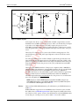
This chapter provides some description of the EP8548A board features including
the PowerPC processor, external interfaces, and u-boot firmware. Figure 2-1 is a
simplified block diagram of the EP board. Figures 2-2 and 2-3 show the top and
bottom views of the board layout. These figures show the headers unpopulated
(i.e., without pins or connectors).
Pre
lim
ina
LEDS
QUAD
GBIT XCVR
SERDES
RS-232
JTAG/COP
(P12)
SERIAL
(P11)
10/100/1000
ETHERNET
(J2, J3)
x1/x4 SRIO/SERDES
ETSEC1/2/3/4
RGMII
MPC8548E
UART0
USER
SWITCH
SW3
CLOCKS
DDR BUS
AMC
CONNECTOR
(P15)
SEP
SRTC
32.768 KHZ
STTM
I2C1
CFG
SWITCH
SW1
SEP
STTM
SPI
CFG
SWITCH
MMC
SW4
IPMB-L/I2C
LOCAL BUS
CPLD
16.67 MHZ
25 MHZ
33.33 MHZ
SDRAM
SODIMM
NVRAM
FLASH
JTAG/
BDM
(P13)
SERIAL
(J7)
T00328A
Figure 2-1. Simplified Block Diagram
MPC8548E
Clocks
Refer to PowerPC Processor in this chapter.
All of the clocks used on the EP board are generated locally. There are a few distinct clocking environments on the board:
•
•
•
System clock and real-time clock.
Ethernet clock.
SERDES clock.
An onboard 33.33 MHz clock oscillator (ECS-3953C or equivalent) generates the
system clock (SYSCLK) input to the MPC8548E processor. This is the primary
P5010000086RA00 Preliminary
2 February 2007
13
AdvancedMC®, EP8548A 1.2
Chapter 2 - Description
MMC
JTAG/BDM
AMC
CONNECTOR
POWER
SW5
PWR-1
MONITOR
(SERIAL)
P13
J6
BT1
1
P11
1
J7
P12
P15
J1
J3
10/100/1000
ETHERNET
DDR2•
SODIMM
P1
SW2
MMC
SERIAL
12V FAN
T00330A
Pre
lim
ina
JTAG/
COP
ry
J2
Figure 2-2. EP Board - Top View
clock input to the device. A zero delay buffer (CY2304 or equivalent) is used to
distribute the 33.33 MHz clock to the processor and to also divide this clock input
to provide a 16.67 MHz real-time clock (RTC) input to the processor. The
16.67 MHz clock input can be used to clock the time base of the processor and to
clock the global timers in the programmable interrupt controller (PIC) of the processor.
The CLK_OUT of the processor routes to the CPLD for timing purposes. The
actual frequency of the CLK_OUT signal depends on the clock selection in the
processor.
An onboard 25 MHz crystal oscillator (FX532 or equivalent) provides the clock
input needed by the Ethernet transceiver. The Ethernet controller (eTSEC) of the
processor requires a 125 MHz external clock input. The Ethernet transceiver generates the 125 MHz clock to the processor (EC_GTX_CLK125) from its 25 MHz
clock input.
The high-speed SERDES interface of the processor requires either a 100 MHz or
125 MHz LVDS clock reference to operate SRIO at either 1.25, 2.5, or 3.125 Gbaud.
A frequency synthesizer device (ICS840001-34) generates the 100 MHz or
125 MHz clock from an onboard 25 MHz crystal oscillator (FX532 or equivalent)
input. An LVDS clock fan-out buffer (ICS8545)selects either the 100 MHz or
125 MHz single-ended input and distributes it to the processor as an LVDS reference clock (SD_REF_CLK, SD_REF_CLK).
NOTE: An option to clock the SERDES interface from CLK3 of the AMC connector is provided. Additionally an option to source CLK3 to the AMC connector is provided. These options
are controlled from a BCSR register; refer to Table 7-9.
Memory
The board has DDR2 SDRAM memory, FLASH memory, and NVRAM memory
(Table 1-1).
DDR2 SDRAM is supported via an SODIMM socket. The memory bus is 64-bit
bus width; refer to SDRAM Organization in this chapter for additional information. There is no ECC option. Access to the SPD functions of the SODIMM module
is from I2C port 1 of the processor; refer to Table 2-3 for its I2C address.
14
2 February 2007
Preliminary P5010000086RA00
AdvancedMC®, EP8548A 1.2
Chapter 2 - Description
P14
SW4
SW1
T00331A
Pre
lim
ina
Figure 2-3. EP Board - Bottom View
ry
SW3
The FLASH memory is Spansion™ MirrorBit. The memory bus is 32-bit bus
width; refer to FLASH Organization in this chapter for additional information.
The NVRAM memory is battery-backed SRAM memory. The memory device is
an STMicro M68AWxxxD or equivalent. The memory bus is 16-bit bus width. An
onboard battery provides backup power for the NVRAM device.
NOTE: The local bus address and data lines are multiplexed. An external demultiplexer, controlled by the address latch enable (LALE) signal, is used to separate the address and data
bus. The local bus is buffered using a data latch for the address lines (SN74LVC32373A or
equivalent) and a bus transceiver for the data lines (SN74LVCH32245A or equivalent).
RS-232
Ethernet
There is one RS-232 serial port available at the front panel (P11). The port communicates via UART0 of the processor. The serial port uses an Intersil ICL3225E
RS-232 transceiver or equivalent.
There are two 10/100/1000 Ethernet ports available at the front panel (J2, J3). Two
additional 10/100/1000 Ethernet ports are available at the AMC connector.
The Ethernet ports communicate via eTSEC1, eTSEC2, eTSEC3, and eTSEC4 of the
processor and use a Marvell® 88E1145 quad transceiver device. The interface to
the processor is RGMII.
Port 3 of the transceiver device routes to AMC port 0 and port 4 of the transceiver
device routes to AMC port 1 in the common options region of the AMC port mappings. The interface to the AMC connector is SERDES using SGMII protocol. An
external PHY or SERDES device is required to complete the interface to the
media.
The MII management connection (MDC/MDIO) to the processor is for configuration and monitoring of the transceiver device. The default Ethernet PHY
addresses are 0b00000, 0b00001, 0b00010, and 0b00011 respectively.
BCSR
P5010000086RA00 Preliminary
Board control and status registers (BCSR) provide hardware control and status to
the processor. BCSR bits selectively enable/disable and configure board features,
and control LEDs, read switch settings, and provide status indications. The BCSR
registers of the EP board are implemented in control logic within a complex pro-
2 February 2007
15
AdvancedMC®, EP8548A 1.2
Chapter 2 - Description
grammable logic device (CPLD). Refer to the Chapter x for BCSR programming
information.
There is one serial EEPROM (SEP) on the local I2C port 1 bus; refer to Table 2-3 for
its I2C address. This SEP device is available for user application storage. The SEP
is a 2-wire, AT24C04 device or equivalent.
STTM
There is one serial temperature and thermal monitor (STTM) device on the local
I2C port 1 bus; refer to Table 2-3 for its I2C address. The STTM part is a 2-wire,
digital temperature sensor. Its functionality is equivalent to the Microchip TCN75
part. The minimum resolution provided by this part is a 9-bit temperature conversion.
SRTC
There is one serial real-time clock (SRTC) device on the local I2C port1 bus; refer
to Table 2-3 for its I2C address. It provides clock and calendar functions for the
board. Counters for tenths/hundredths of seconds, seconds, minutes, hours, day,
date, month, year, and century are provided. Its functionality is equivalent to the
STMicrodevices M41T81 part. An onboard battery provides backup power for the
SRTC device.
MMC
Pre
lim
ina
JTAG/COP
ry
SEP
The P12 header provides access to the COP port of the processor for debug access.
Additionally P12 can be configured with jumper settings to give access to the
CPLD JTAG. Refer to JTAG/COP Configuration in Chapter 4.
The module management controller (MMC) funtionality required for AMC.0
compliance is implemented in an MCF5213 Coldfire processor. The MMC communicates with the ATCA carrier or microTCA carrier hub over the IPMB-L bus
using I2C protocol. The carrier and MMC communicate through a limited set of
IPMI commands.
Two serial temperature sensors and a serial EEPROM implement the temperature
sensor and FRU information storage device requirements for AMC.0 compliance.
These devices are accessed via the SPI bus of the Coldfire processor. Additionally
access to the RS-232 serial port and JTAG/BDM port of the Coldfire processor are
provided for development purposes.
Refer to Chapter 5 for more information and pinouts for the connectors.
PowerPC Processor
The EP board incorporates an MPC8548E PowerQUICC III integrated host processor. This 32-bit processor includes an integrated PowerPC core and peripheral
interfaces that can be used in a variety of embedded networking, telecom transmission and switching, 3G wireless infrastructure, storage, and high-end imaging
applications. The MPC8548E processor incorporates:
•
•
•
•
•
•
•
•
•
16
e500 core scaling up to 1.33 GHz.
DDR memory controller operating at up to 667 MHz data rate.
Local bus controller operating at up to 166 MHz.
OCeaN switch fabric.
Dual UART (DUART).
Dual I2C interfaces (master or slave mode).
Serial RapidIO interface unit.
PCI Express interface unit (not accessible on EP board).
Four enhanced three-speed Ethernet controllers (eTSEC).
2 February 2007
Preliminary P5010000086RA00
AdvancedMC®, EP8548A 1.2
Chapter 2 - Description
•
•
•
•
•
Two PCI/PCI-X controllers (not accessible on EP board).
Programmable interrupt controller (PIC).
Four-channel DMA controller.
System performance monitor.
Integrated security engine.
SDRAM Organization
2 GByte
128M x 64, 200-Pin DDR2 SDRAM SODIMM
Micron MT16HTF12864H or equivalent
2 bit bank address (BA0-BA1)
14 bit row address (A0-A13)
10 bit column address (A0-A9)
2 module rank address (S0, S1)
ry
1 GByte
The DDR SDRAM clock speed is generated internal to the CPU and is equal to
1/2 the e500 core complex bus clock (ccb_clk). The maximum is 667 MHz data
rate (333.33 MHz clock) for the MPC8548E processor with a 33.33 MHz SYSCLK.
Pre
lim
ina
Memory Clock
256M x 64, 200-Pin DDR2 SDRAM SODIMM
Micron MT16HTS25664H or equivalent
3 bit bank address (BA0-BA2)
14 bit row address (A0-A13)
10 bit column address (A0-A9)
2 module rank address (S0, S1)
FLASH Organization
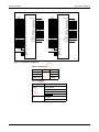
The FLASH memory on the EP board is accessed using the general purpose chip
select machine (GPCM) of the processor. Figure 2-4 shows the address and data
line connections. An offset is needed when issuing commands to the FLASH
devices due to the address line connections.
Table 2-1 lists the FLASH memory devices and their device IDs that are currently
supported on the board. Refer to the Spansion datasheets for detailed information
about the FLASH memory devices. Command codes for all Spansion devices are
the same. Device ID varies among the different devices. Sector addresses also
vary among the different devices.
The following guidelines apply to x32 ported FLASH memory:
•
FLASH devices configured in 16-bit mode.
•
Sector and chip erases should be performed only on a long word (32-bit)
basis.
•
Programming should be done on a long word (32-bit) basis if possible.
Processor I/O Interface Signals
Table 2-2 lists the processor I/O interface signals used on the EP board.
P5010000086RA00 Preliminary
2 February 2007
17
AdvancedMC®, EP8548A 1.2
Chapter 2 - Description
U16
+3.3V
LCS0N
BY TE#
CE#
OE#
WE#
RESET#
LA29
LA28
LA27
LA26
LA25
LA24
LA23
LA22
LA21
LA20
LA19
LA18
LA17
LA16
LA15
LA14
LA13
LA12
LA11
LA10
LA9
ILA8
LA7
LA6
LA5
LA4
WP#/ACC
DQ0
DQ1
DQ2
DQ3
DQ4
DQ5
DQ6
DQ7
DQ8
DQ9
DQ10
DQ11
DQ12
DQ13
DQ14
DQ15/A-1
LD31
LD30
LD29
LD28
LD27
LD26
LD25
LD24
LD23
LD22
LD21
LD20
LD19
LD18
LD17
LD16
A0
A1
A2
A3
A4
A5
A6
A7
A8
A9
A10
A11
A12
A13
A14
A15
A16
A17
A18
A19
A20
A21
A22
A23
A24
A25
WP#/ACC
DQ0
DQ1
DQ2
DQ3
DQ4
DQ5
DQ6
DQ7
DQ8
DQ9
DQ10
DQ11
DQ12
DQ13
DQ14
DQ15/A-1
ry
A0
A1
A2
A3
A4
A5
A6
A7
A8
A9
A10
A11
A12
A13
A14
A15
A16
A17
A18
A19
A20
A21
A22
A23
A24
A25
RY /BY #
Pre
lim
ina
LA29
LA28
LA27
LA26
LA25
LA24
LA23
LA22
LA21
LA20
LA19
LA18
LA17
LA16
LA15
LA14
LA13
LA12
LA11
LA10
LA9
ILA8
LA7
LA6
LA5
LA4
U17
+3.3V
LCS0N
LD15
LD14
LD13
LD12
LD11
LD10
LD9
LD8
LD7
LD6
LD5
LD4
LD3
LD2
LD1
LD0
RY /BY #
BY TE#
CE#
OE#
WE#
RESET#
T00327A
Figure 2-4. FLASH Address and Data Lines
Table 2-1. FLASH Devices
Device
S29GL128
MFG ID
Device ID
0001
0x2101
S29GL256
0x2201
S29GL512
0x2301
Table 2-2. I/O Signals
Interface
Serial
Signal
UART_SOUT0
UART_SIN0
UART_CTS0
UART_RTS0
I2C
IIC1_SDA
IIC1_SCL
18
2 February 2007
Preliminary P5010000086RA00
AdvancedMC®, EP8548A 1.2
Chapter 2 - Description
Table 2-2. I/O Signals (continued)
Interface
Ethernet
Signal
EC_MDC
EC_MDIO
EC_GTX_CLK125
TSEC1_TXD[3:0]
TSEC1_TX_EN
TSEC1_GTX_CLK
TSEC1_RXD[3:0]
TSEC1_RX_DV
ry
TSEC1_RX_CLK
TSEC2_TXD[3:0]
TSEC2_TX_EN
TSEC2_GTX_CLK
Pre
lim
ina
TSEC2_RXD[3:0]
TSEC2_RX_DV
TSEC2_RX_CLK
TSEC3_TXD[3:0]
TSEC3_TX_EN
TSEC3_GTX_CLK
TSEC3_RXD[3:0]
TSEC3_RX_DV
TSEC3_RX_CLK
TSEC4_TXD[3:0]
TSEC4_TX_EN
TSEC4_GTX_CLK
TSEC4_RXD[3:0]
TSEC4_RX_DV
TSEC4_RX_CLK
SRIO
SD_TX[4:7]
SD_TX[4:7]
SD_RX[4:7]
SD_RX[4:7]
SD_REF_CLK
SD_REF_CLK
I2C Devices
The evaluation board has several I2C bus devices: STTM, SEP, SRTC, SODIMM.
Table 2-3 describes the I2C address map.
P5010000086RA00 Preliminary
2 February 2007
19
AdvancedMC®, EP8548A 1.2
Chapter 2 - Description
Table 2-3. I2C Address Map
Device
Function
I2C Addressing
SODIMM SDP, 2K device (256 x 8)
0xA0 - 0xA1
0b1010000x
SEP
Serial EEPROM,4K device (512 x 8)
0xAC - 0xAF
0b1010110x (256)
0b1010111x (256)
STTM
Serial temperature and thermal monitor 0x90 - 0x91
0b1001000x
SRTC
Serial real-time-clock
0b1101000x
0xD0 - 0xD1
Operating Modes
•
•
Stand-alone mode.
AdvancedMC mode.
ry
The EP board can operate in two different modes:
Thermal
Pre
lim
ina
Stand-alone mode is primarily intended for development; AMC mode provides
the ability to use the same development board in a carrier card or chassis environment. There are no configuration options to select to switch between stand-alone
and AMC modes. The only real difference is where power is applied. Refer to
Power in Chapter 5.
The MPC8548E processor is fitted with a heat sink. The choice of size and type of
heat sink is dependant on the environment in which the board is operating. Factors such as processor speed, ambient temperature, and air flow all dictate the
specific characteristics of the heat sink required. Additionally, the choice of heat
sink is dependant on the space available which is ultimately determined by the
mechanical constraints of the system in which the EP board will operate. The heat
sink used when the card is situated in a chassis environment with forced air flow
will differ from that used when the card operates stand-alone. Refer to the
MPC8548E Reference Manual for the processor thermal characteristics.
Firmware
U-boot is open source firmware for the embedded PowerPC architecture. It can be
installed in a boot ROM and used to initialize and test hardware or to download
and run application code.
The EP8548A board is shipped with the u-boot firmware residing in FLASH
memory. U-boot loads at the address 0xFFF00000. U-boot utilities provide the
ability to initialize the board and auto execute an operating system or application.
Refer to online u-boot documentation for complete information about u-boot and
its utilities.
Restoring MAC Addresses
The EP board has four media access control (MAC) address assigned to it. The
MAC address is the physical address of a device connected to a network,
20
2 February 2007
Preliminary P5010000086RA00
AdvancedMC®, EP8548A 1.2
Chapter 2 - Description
expressed as a 48-bit hexadecimal number. The EP boards are assigned MAC
addresses during manufacture using the following convention:
Enet controller 1 MAC = 0x0010ECxxxxxx ORed with 0x000000000000
Enet controller 2 MAC = 0x0010ECxxxxxx ORed with 0x000000800000
Enet controller 3 MAC = 0x0010ECxxxxxx ORed with 0x000000400000
Enet controller 4 MAC = 0x0010ECxxxxxx ORed with 0x000000C00000
where
xxxxxx
EP board serial number. The serial number can be found
in decimal form on a label affixed to the Ethernet port on
the board (e.g., 007573).
ry
For example, a board with a serial number of 007573 decimal (001D95 hexadecimal) has a MAC address of:
00:10:EC:00:1D:95 for Enet controller 1
00:10:EC:80:1D:95 for Enet controller 2
Pre
lim
ina
If it becomes necessary to restore a missing or corrupted MAC address, use the
above procedure to determine the EP board’s MAC addresses and issue the following commands in u-boot:
setenv ethaddr <MAC ADDRESS1> ENTER
setenv eth1addr <MAC ADDRESS2> ENTER
setenv eth2addr <MAC ADDRESS3> ENTER
setenv eth3addr <MAC ADDRESS4> ENTER
saveenv ENTER
P5010000086RA00 Preliminary
2 February 2007
21
Pre
lim
ina
ry
AdvancedMC®, EP8548A 1.2
22
2 February 2007
Preliminary P5010000086RA00
Getting Started
Chapter 3
ry
This chapter describes how to get the EP board up and running in stand-alone
mode including initial configuration, connection, and powerup. The board comes
preprogrammed with u-boot firmware. An RS-232 serial monitor connection is
required to access u-boot utilities. A network connection is required to transfer
files to the EP board using TFTP.
To start up and begin communicating with the EP board:
NOTE: The EP board does not require any special configuration to operate in stand-alone
mode.
Pre
lim
ina
1. Establish a serial connection; refer to Serial Monitor Connection in this chapter.
2. Establish a network connection, if required; refer to Network Connection in
this chapter.
3.
Apply power; refer to Power Up in this chapter.
Serial Monitor Connection
A terminal emulator program on the host machine (e.g., minicom, Tera Term, or
HyperTerminal) or a dumb terminal is required to interact with the EP board. To
establish a serial monitor connection with the host system:
1.
Connect the RJ-45 patch cable to the RJ-45 monitor port (Fig. 2-2).
2.
Connect the opposite end of the RJ-45 cable to the RJ-45 to DB-9 adapter.
3. Connect the DB-9 adapter to a serial port on the host machine (or dumb terminal).
The default settings for the monitor port are:
•
•
•
•
•
115200 baud.
8 data bits.
1 stop bit.
No parity.
No flow control.
Network Connection
A network connection between the development target (i.e., EP board) and host
system is needed if planning to use TFTP services to transfer files to the EP board.
A TFTP server must be running on the host machine to use the network connection for file transfer. Connect to the EP board in one of two ways: directly or
through a network hub or switch.
P5010000086RA00 Preliminary
2 February 2007
23
AdvancedMC®, EP8548A 1.2
Chapter 3 - Getting Started
Direct
To directly connect to the host machine, use a Ethernet crossover cable connected
between the RJ-45 Ethernet port on the EP board (Fig. 2-2) and the Ethernet port
on the host machine.
Hub or Switch
To connect to the host machine via a hub or switch, use a standard Ethernet patch
cable connected between the RJ-45 Ethernet port on the EP board (Fig. 2-2) and a
free port on the hub.
NOTE: Most new Ethernet cards, hubs, and switches have auto-crossover capabilities which
means the same cable may be able to be used for either direct, hub, or switch connection.
ry
Power Up
NOTE: Start the terminal emulation program (e.g., minicom, Tera Term, or HyperTerminal) or
make sure the dumb terminal is connected before powering up the EP board.
Pre
lim
ina
When operating stand-alone, an external cooling fan is required. Optionally, a
12 VDC fan can be powered from the fan header (P1) of the EP board; refer to
Table 5-6. The fan should be placed next to the board and in a position so as to
maximize airflow over the processor.
After all connections have been properly made, connect the 12 VDC power supply to the barrel connector P5 (Fig. 2-2). The EP board will boot up into u-boot
automatically. Refer to online u-boot documentation for complete information
about u-boot and its utilities.
24
2 February 2007
Preliminary P5010000086RA00
Setup
Chapter 4
This chapter describes the various configuration switches that setup the EP8548A
board for operation.
ry
SRIO Configuration
Switches SW1 configure SRIO options. Table 4-1 describes the configuration
options. Refer to Figure 2-3 for the location of the switch.
Table 4-1. SERDES Port Configuration (SW1[1:3])
Pre
lim
ina
Option
1234
Description
100x
x4 SRIO, 2.5 Gbaud interface; 100 MHz reference clock
101x
x4 SRIO, 3.125 Gbaud interface; 125 MHz reference clock
110x
x4 SRIO, 1.25 Gbaud interface; 100 MHz reference clock
xxx0
Large system size; up to 65,536 devices
xxx1
Small system size; up to 256 devices
NOTES:
1. on = closed position = logic 0; off = open position = logic 1.
2. Refer to the MPC8548E Reference Manual for additional information.
MMC Configuration
Switch SW4 configures the MMC processor options. Table 4-2 describes the configuration options. Refer to Figure 2-3 for the location of the switch.
NOTE: This switch is primarily for development purposes. It is factory set and should not be
changed.
Table 4-2. MMC Configuration (SW4[1:4])
Position
Description
1
RCON; selects serial FLASH programming mode:
0 = enable serial FLASH programming mode
1 = disable serial FLASH programming mode
2
JTAG_EN; selects between debug and JTAG mode:
0 = debug mode
1 = JTAG mode
3
CLKMOD[1:0]; determines the clock mode:
00 = PLL disabled
10 = PLL in normal mode
4
NOTES:
1. on = closed position = logic 0; off = open position = logic 1
2. Refer to the MCF5213 Reference Manual for additional information.
P5010000086RA00 Preliminary
2 February 2007
25
AdvancedMC®, EP8548A 1.2
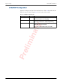
Chapter 4 - Setup
JTAG/COP Configuration
Jumper J6 configures the JTAG chain and COP mode. Table 4-3 describes the configuration options. Refer to Figure 2-2 for the location of the switch.
Table 4-3. JTAG/COP Configuration (J6)
Purpose
Setting
Function
J6: 1-2
P12 operates in COP mode to support hardware and
software development and debugging.
JTAG (CPLD only)
J6: 2-3
JTAG chain active at P12. This setting puts only the
CPLD in the JTAG chain to support programming.
JTAG (complete)
J6: open JTAG chain active at P12. This setting completes the
JTAG chain at P12 and includes:
ry
COP
Pre
lim
ina
AMC->CPU->CPLD->MMC->ETH_PHY->AMC
26
2 February 2007
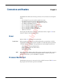
Preliminary P5010000086RA00
Connectors and Headers
Chapter 5
The EP8548A board has the following connectors for I/O functions and expandability:
•
•
•
•
•
•
Pre
lim
ina
•
One connector for power (used for stand-alone only).
One RJ-45 connector for processor RS-232 monitor port.
Two RJ-45 connectors for the 10/100/1000 Ethernet ports.
One 200-pin SODIMM connector.
One 2 × 8 header for JTAG/COP access.
One 1 × 3 header for MMC RS-232 serial port.
One 2 × 8 header for MMC debug port.
One 1 × 2 header for external 12 VDC fan.
AMC bus connector.
ry
•
•
This chapter describes these connectors and headers. Refer to Figure 2-2 for the
locations of these connectors and headers.
Power
Refer to Table 1-1 for input power requirements.
Stand-Alone
When operating in stand-alone mode the EP board is powered from +12 VDC
supplied through the barrel connector (PWR-1). An onboard regulator generates
+3.3 VDC to power the MMC. The specifications for the mating connector are:
Inner diameter = 2.1 mm (0.083 inches)
Outer diameter = 5.5 mm (0.217 inches)
Outer shell is GND
Inner shell is 12 VDC
AMC
When operating in AMC mode the EP board is powered from the AMC connector
of the carrier card or from the chassis backplane. Both +12 VDC to power the
board and +3.3 VDC to power the MMC are required.
Processor Monitor Port
The RS-232 monitor port is connector P11. It is an RJ-45 connector. Table 5-1 shows
the port pinout. The monitor port is from UART0.
P5010000086RA00 Preliminary
2 February 2007
27
AdvancedMC®, EP8548A 1.2
Chapter 5 - Connectors and Headers
Table 5-1. Monitor Port Pinout (P11)
Pin
Function
Pin
Function
1
—
5
RXD
2
—
6
TXD
3
—
7
CTS
4
GND
8
RTS
NOTE:
1. Pin numbering is from right (1) to left (8) when
looking into the RJ-45 jack with the locking tab on
top.
ry
Ethernet Port
Pre
lim
ina
The 10/100/1000 Ethernet ports are connectors J2 and J3. The connectors are
shielded RJ-45 jacks. Table 5-2 shows the RJ-45 jack pinout.
Table 5-2. Ethernet Port Pinout (J2, J3)
Pin
Function
Pin
Function
1
TXD+
5
—
2
TXD-
6
RXD-
3
RXD+
7
—
4
—
8
—
NOTE:
1. Pin numbering is from right (1) to left (8) when
looking into the RJ-45 jack with the locking tab on
top.
JTAG/COP Port
The JTAG/COP port is P12. It is a 2 × 8 (0.1 × 0.1) header. Table 5-3 shows the COP
header pinout.
Table 5-3. COP Port Pinout (P12)
Pin
28
Function
Pin
Function
1
TDO
2
GND
3
TDI
4
TRST
5
+3.3V
6
+3.3V
7
TCK
8
CHKSTOP_IN
9
TMS
10
—
11
SRESET
12
GND
13
HRESET
14
—
15
CHKSTOP_OUT
16
GND
2 February 2007
Preliminary P5010000086RA00
AdvancedMC®, EP8548A 1.2
Chapter 5 - Connectors and Headers
MMC Serial Port
The MMC serial port is connector J7. It is a 1 × 3 (0.1 × 0.1) header. Table 5-4 shows
the pinout.
Table 5-4. MMC Serial Port Pinout (J7)
Pin
Function
TXD
2
GND
3
RXD
ry
1
MMC Debug Port
Pre
lim
ina
The MMC debug port is P13. It is a 2 × 8 (0.1 × 0.1) header. Table 5-5 shows the
utility header pinout.
Table 5-5. MMC Debug Port Pinout (P13)
Pin
Function
Pin
Function
1
—
2
TMS
3
GND
4
TRST
5
GND
6
TCK
7
RST_IN
8
TDI
9
IPMCV
10
TDO
11
GND
12
ALLPST
13
ALLPST
14
ALLPST
15
ALLPST
16
—
12 VDC Fan Header
The 12 VDC fan header is connector P1. It is a 1 × 2 (0.1 × 0.1) header. Table 5-4
shows the pinout.
Table 5-6. 12 VDC Fan Header Pinout (P1)
Pin
Function
1
GND
2
+12V
AMC Connector
Table 5-7 lists the pin assignments for the AMC connector (P15). The AMC connector signal assignments follow the AMC standard.
P5010000086RA00 Preliminary
2 February 2007
29
AdvancedMC®, EP8548A 1.2
Chapter 5 - Connectors and Headers
Table 5-7. AMC Connector (P15)
Pin
Signal
Pin
Signal
1
GND
170
GND
2
+12V
169
TDI
3
PS1
168
TDO
4
+3.3V IPMCV
167
TRST
5
GA0
166
TMS
6
—
165
TCLK
7
GND
164
GND
8
—
163
—
+12V
162
GND
161
—
11
TX0+
160
12
TX0-
159
13
GND
158
14
RX0+
157
—
15
RX0-
156
—
16
GND
155
GND
17
GA1
154
—
18
+12V
153
—
19
GND
152
GND
20
TX1+
151
—
21
TX1-
150
—
22
GND
149
GND
23
RX1+
148
—
24
RX1-
147
—
25
GND
146
GND
26
GA2
145
—
27
+12V
144
—
28
GND
143
GND
29
—
142
—
30
—
141
—
31
GND
140
GND
32
—
139
—
33
—
138
—
34
GND
137
GND
35
—
136
—
36
—
135
—
37
GND
134
GND
38
—
133
—
39
—
132
—
40
GND
131
GND
41
ENABLE
130
—
ry
9
10
GND
—
—
Pre
lim
ina
GND
30
2 February 2007
Preliminary P5010000086RA00
AdvancedMC®, EP8548A 1.2
Chapter 5 - Connectors and Headers
Table 5-7. AMC Connector (P15) (continued)
Pin
Signal
Pin
Signal
42
+12V
129
—
43
GND
128
GND
44
TX4+
127
—
45
TX4-
126
—
46
GND
125
GND
47
RX4+
124
—
48
RX4-
123
—
49
GND
122
GND
50
TX5+
121
51
TX5-
120
52
GND
119
53
RX5+
118
54
RX5-
117
55
GND
116
GND
56
SCL_L
115
—
57
+12V
114
—
58
GND
113
GND
59
TX6+
112
—
60
TX6-
111
—
61
GND
110
GND
62
RX6+
109
—
63
RX6-
108
—
64
GND
107
GND
65
TX7+
106
—
66
TX7-
105
—
67
GND
104
GND
68
RX7+
103
—
69
RX7-
102
—
70
GND
101
GND
71
SDA_L
100
—
72
+12V
99
—
73
GND
98
GND
74
—
97
—
75
—
96
—
76
GND
95
GND
77
—
94
—
78
—
93
—
79
GND
92
GND
80
CLK3+
91
—
81
CLK3-
90
—
82
GND
89
GND
ry
—
—
GND
—
Pre
lim
ina
—
P5010000086RA00 Preliminary
2 February 2007
31
AdvancedMC®, EP8548A 1.2
Chapter 5 - Connectors and Headers
Table 5-7. AMC Connector (P15) (continued)
Pin
Signal
Pin
Signal
PS0
88
—
84
+12V
87
—
85
GND
86
GND
Pre
lim
ina
ry
83
32
2 February 2007
Preliminary P5010000086RA00
Operation
Chapter 6
This chapter describes the reset switch and board LED indications for the
EP8548A board. It also provides some firmware description and communication
information.
ry
System Reset Pushbutton
Board LEDs
Pre
lim
ina
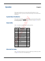
The system reset pushbutton (SW2) can be used to reset the board. This pushbutton activates a hard reset (HRESET) to the board. Refer to Figure 2-2 for the location of the pushbutton.
Table 6-1 describes the indications for the EP board LEDs
Table 6-1. Board LEDs
LED
Definition (On)
Color
CR9
AMC hot swap indicator
Blue
CR10
AMC LED1
Red
CR8
AMC LED2
Green
CR11
AMC LED3
Amber
CR22
+12 VDC power OK
Green
CR20
+3.3V power OK
Green
CR21
+2.5V PHY power OK
Green
CR19
+1.8V DDR power OK
Green
CR18
+1.1V e500 power OK
Green
CR12
User LED0
Green
CR13
User LED1
Green
CR14
Ethernet port 2 RXD
Green
CR15
Ethernet port 2 TXD
Green
CR16
Ethernet port 3 RXD
Green
CR17
Ethernet port 3 TXD
Green
NOTE: AMC LEDs are under MMC control.
Ethernet Port LEDs
Table 6-2 describes the indications given by the Ethernet port LEDs (J2, J3). Refer
to Figure 2-2 for the location of the Ethernet port.
P5010000086RA00 Preliminary
2 February 2007
33
AdvancedMC®, EP8548A 1.2
Chapter 6 - Operation
Table 6-2. Ethernet Port (J2, J3) LEDs
State
Indication
LED1 (Yellow)
LED2 (Green/Amber)
Off
No RXD/TXD activity
10 Mbps
On
RXD/TXD activity
100 Mbps (amber)
1000 Mbps (green)
User Applications
•
•
115200 baud (default).
8 data bits.
1 stop bit.
No parity.
No hardware handshake.
Pre
lim
ina
•
ry
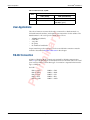
The u-boot firmware assumes the board is connected to a dumb terminal or a
PC-based terminal emulator, and requires user intervention for the utilities. The
dumb terminal or PC serial port should be set as follows:
•
•
Proper interfacing to the serial port via the correct RS-232 connections must be
insured as described in RS-232 Connection in this chapter.
RS-232 Connection
A DB-9 (or DB-25) to RJ-45 connection is required for RS-232 communication.
Table 5-1 provides the pinouts for the RJ-45 connector. The EP board has its serial
ports wired as DTE. A null modem type of connection is required when interfacing to a DTE port.
For DTE:
DB9-3 = TXD
DB9-2 = RXD
DB9-8 = CTS
DB9-7 = RTS
DB9-5 = GND
34
DB25-2 = TXD
DB25-3 = RXD
DB25-5 = CTS
DB25-4 = RTS
DB25-7 = GND
2 February 2007
Preliminary P5010000086RA00
Board Control and Status Registers
Chapter 7
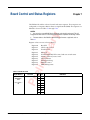
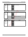
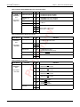
The EP8548A board has onboard control and status registers. These registers are
configured as x8 registers. Bit 0 is the most significant bit (MSB). The registers are
defined as shown in Tables 7-1 through 7-10.
ry
NOTES:
1. Any unused or reserved BCSR bits should always write back the value read. This will
help guarantee that revisions to the board will be backward compatible with existing software.
2. The base address of the BCSR is determined by the firmware or application; refer to
Table 8-1.
Pre
lim
ina
Register values at reset (values in binary):
Register 0
Register 1
Register 2
Register 3
Register 4
Register 5
Register 6
Register 7
Register 8
Register 9
Board ID
CPLD code revision
FLASH status
Reserved
FLASH, EEPROM, LED control and user switch status
Monitor, Ethernet, reset control
Interrupt status
Interrupt masking
SERDES control
MMC debug status
Table 7-1. BCSR0 - Board ID
Byte Address
BASE
ADDRESS +
0x0
reset value =
ID
P5010000086RA00 Preliminary
Function
ID
Bit R/W
0
RO
1
RO
2
RO
3
RO
4
RO
5
RO
6
RO
7
RO
Definition
ID = 0x4 = EP8548 1.2
2 February 2007
35
AdvancedMC®, EP8548A 1.2
Chapter 7 - Board Control and Status Registers
Table 7-2. BCSR1 - CPLD Code Revision
BASE
ADDRESS +
0x1
Function
CPLD revision
reset value =
REV
Bit R/W
0
RO
1
RO
2
RO
3
RO
4
RO
5
RO
6
RO
7
RO
Table 7-3. BCSR2 - FLASH Status
BASE
ADDRESS +
0x2
reset value =
0000 0x00
Function
Reserved
Bit R/W
0
RO
1
RO
2
RO
3
RO
REV = revision of CPLD code
Pre
lim
ina
Byte Address
Definition
ry
Byte Address
4
RO
FLASH ready/busy
5
RO
Reserved
6
RO
7
RO
Definition
0 = FLASH operation executing and busy
1 = FLASH operation complete (ready)
Table 7-4. BCSR3 - Reserved
Byte Address
BASE
ADDRESS +
0x3
reset value =
0000 0000
36
Function
Reserved
Bit R/W
0
RO
1
RO
2
RO
3
RO
4
RO
5
RO
6
RO
7
RO
2 February 2007
Definition
Preliminary P5010000086RA00
AdvancedMC®, EP8548A 1.2
Chapter 7 - Board Control and Status Registers
Table 7-5. BCSR4 - FLASH, EEPROM, LED Control and User Switch Status
Function
BASE
ADDRESS +
0x4
FLASH write protect
0
R/W 0 = FLASH write protect disabled
1 = FLASH write protect enabled
EEPROM write
protect
1
R/W 0 = EEPROM write protect disabled
1 = EEPROM write protect enabled
User LED0
2
User LED1
3
R/W 0 = LED off
R/W 1 = LED on
User switch
4
RO
BCSR4.4 is position 1 on switch
5
RO
6
RO
Switch closed = logic 0 = on
Switch open = logic 1 = off
7
RO
reset value =
0000 uuuu
Bit R/W
Table 7-6. BCSR5 - Monitor, Ethernet, Reset Control
BASE
ADDRESS +
0x5
reset value =
1000 0000
Function
Bit R/W
Pre
lim
ina
Byte Address
Definition
ry
Byte Address
Definition
Monitor port
0
R/W 0 = disable monitor transceiver
1 = enable monitor transceiver
Reserved
1
RO
2
RO
3
RO
Ethernet PHY
4
R/W 0 = enable Ethernet PHY
1 = disable Ethernet PHY (reset)
Software reset
5
R/W 1 = enable HRESET
Reserved
6
RO
7
RO
Table 7-7. BCSR6 - Interrupt Status
Byte Address
BASE
ADDRESS +
0x6
reset value =
xxxx xx00
Function
Interrupt
Reserved
P5010000086RA00 Preliminary
Bit R/W
Definition
0
RO
0 = Ethernet 0 IRQ active
1 = Ethernet 0 IRQ inactive
1
RO
0 = Ethernet 1 IRQ active
1 = Ethernet 1 IRQ inactive
2
RO
0 = Ethernet 2 IRQ active
1 = Ethernet 2 IRQ inactive
3
RO
0 = Ethernet 3 IRQ active
1 = Ethernet 3 IRQ inactive
4
RO
0 = SRTC IRQ active
1 = SRTC IRQ inactive
5
RO
0 = STTM IRQ active
1 = STTM IRQ inactive
6
RO
7
RO
2 February 2007
37
AdvancedMC®, EP8548A 1.2
Chapter 7 - Board Control and Status Registers
Table 7-8. BCSR7 - Interrupt Masking
BASE
ADDRESS +
0x7
Function
Interrupt
reset value =
1111 1100
Definition
0
R/W 0 = Ethernet 0 IRQ unmasked
1 = Ethernet 0 IRQ masked
1
R/W 0 = Ethernet 1 IRQ unmasked
1 = Ethernet 1 IRQ masked
2
R/W 0 = Ethernet 2 IRQ unmasked
1 = Ethernet 2 IRQ masked
3
R/W 0 = Ethernet 3 IRQ unmasked
1 = Ethernet 3 IRQ masked
4
R/W 0 = SRTC IRQ unmasked
1 = SRTC IRQ masked
5
R/W 0 = STTM IRQ unmasked
1 = STTM IRQ masked
6
RO
7
RO
Pre
lim
ina
Reserved
Bit R/W
ry
Byte Address
Table 7-9. BCSR8 - SERDES Control
Byte Address
BASE
ADDRESS +
0x8
reset value =
1100 0000
Function
Bit R/W
Definition
SERDES clock
select
0
R/W 0 = AMC connector
1 = onboard
AMC CLK3
1
R/W 0 = onboard SERDES clock enabled at AMC CLK3
1 = onboard SERDES clock disabled at AMC CLK3
NOTE: BCSR8[0] = 1 is required to enable AMC CLK3.
Reserved
2
R/W
3
R/W
4
R/W
5
R/W
6
RO
7
RO
Table 7-10. BCSR9 - MMC Debug Status
Byte Address
BASE
ADDRESS +
0x9
reset value =
x000 000
38
Function
Bit R/W
ALLPST
0
R/W Status of ALLPST at P13
Reserved
1
R/W
2
R/W
3
R/W
4
R/W
5
R/W
6
RO
7
RO
2 February 2007
Definition
Preliminary P5010000086RA00
Memory and Interrupts
Chapter 8
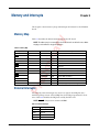
This chapter contains memory map and interrupt information for the EP8548A
board.
ry
Memory Map
Table 8-1 describes the default memory map for the EP board.
Table 8-1. Memory Map
Chip Select
Pre
lim
ina
NOTE: The address map is recommended for the EP board and is as defined in u-boot. Other
mappings can be utilized for any given application.
Address
Size
LCS0
FLASH
0xF8000000
128 MB
32-bit, GPCM
LCS1
NVRAM
0x??
1 MB
16-bit, GPCM
LCS2
BCSR
0x??
32 KB
8-bit, GPCM
LCS3
—
—
—
Unused
LCS4
—
—
—
Unused
LCS5
—
—
—
Unused
LCS6
—
—
—
Unused
LCS7
—
—
—
Unused
MCS0
DDR SDRAM
0x00000000
1 GB
64-bit, DDR controller
0x40000000
1 GB
64-bit, DDR controller
—
—
Unused
—
—
Unused
0xE0000000
1 MB
Memory mapped processor registers
MCS1
MCS2
MCS3
—
Function
CCSRBAR
Description
External Interrupts
All onboard, external interrupts are active low signals. Each IRQ line has a
10 Kohm pull-up resister. All used IRQ lines should be programmed for level
sense. Table 8-2 identifies the IRQ lines used by the EP board.
NOTE: IRQ_OUT of the processor connects to the MMC.
Table 8-2. External Interrupts
IRQ
P5010000086RA00 Preliminary
Interrupt Source
IRQ0
Unused
IRQ1
Unused
IRQ2
SRTC
IRQ3
STTM
2 February 2007
39
AdvancedMC®, EP8548A 1.2
Chapter 8 - Memory and Interrupts
Table 8-2. External Interrupts (continued)
IRQ
Interrupt Source
Ethernet port 1
IRQ5
Ethernet port 2
IRQ6
Ethernet port 3
IRQ7
Ethernet port 4
IRQ8
Unused
IRQ9
Unused
IRQ10
Unused
IRQ11
Unused
Pre
lim
ina
ry
IRQ4
40
2 February 2007
Preliminary P5010000086RA00
Mechanical Dimensions
Appendix A
This appendix contains mechanical dimension drawings for the EP8548A board.
The board is designed as a single-width, full-height AMC module. Figure A-1
shows the dimensions for the EP board.
Pre
lim
ina
ry
NOTE: The dimensions in this document are believed correct, but if this unit is to be placed
into a housing that has cut outs, an actual unit must be procured to verify all required connector cut outs. In addition, the vendor datasheets for the connectors should be referenced to
determine the tolerances of the connectors.
P5010000086RA00 Preliminary
2 February 2007
41
Appendix A - Mechanical Dimensions
42
7.110
[180.60]
6.382
[162.10]
0.148
[3.75]
SW5
PWR-1
P13
J6
1
BT1
Pre
lim
ina
1
J7
1.800
[45.72]
P15
2.697
J1
J3
[68.50]
P12
2.766
[70.25]
2.894
[73.50]
P11
[2.35]
[8.89]
0.093
0.811
[20.60]
4.465
[113.41]
Figure A-1. Mechanical Dimensions
P1
[5.00]
0.197
2 February 2007
0.350
J2
SW2
ry
INCHES
MILLIMETERS
T00329A
AdvancedMC®, EP8548A 1.2
Preliminary P5010000086RA00
Pre
lim
ina
ry
AdvancedMC®, EP8548A 1.2
P5010000086RA00 Preliminary
2 February 2007
43
Pre
lim
ina
ry
AdvancedMC®, EP8548A 1.2
Embedded Planet
4760 Richmond Road, Suite 400
Warrensville Heights, OH 44128
www.embeddedplanet.com
Form P5010000086RA00 Preliminary Litho in U.S.A. Feb2007
Copyright © 2007 Embedded Planet, LLC. All Rights Reserved.
Phone: 216.245.4180
Fax: 216.292.0561