1
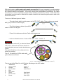
User´s Manual
aero 20A
Antes de utilizar el equipo, lea la sección
“Precauciones de seguridad” de este
manual. Conserve este manual para
futuras consultas.
Before operating the device, please read
the “Safety precautions” section of this
manual. Retain this manual for future
reference.
CONTENTS
SAFETY PRECAUTIONS
3
WARRANTY
4
DECLARATION OF CONFORMITY
5
INTRODUCTION
6
7a8
CONFIGURATIONS
12 aero 20A + 6 LX-218CA
24 aero 20A + 12 LX-218CA
SPECIFICATIONS
9
LINE DRAWINGS
9
10 a 12
AMPLIFIER
Description
ON / OFF
Overload Indicators
Equalisation
Overheating
Low mains voltage
Current consumption
Troubleshooting
CHANGE OF CONFIGURATION
13
14 a 15
RIGGING SYSTEM
16
APPENDIX I
Line conections: unbalanced and balanced
17
APPENDIX II
DASnet cables
Manual del Usuario / aero 20A / User’s Manual
æro 20A
Precauciones de Seguridad
Safety Precautions
Cajas acústicas activas / Self-powered loudspeaker enclosures
El signo de exclamación dentro de un triángulo indica la
existencia de importantes instrucciones de operación y
mantenimiento en la documentación que acompaña al producto.
Conserve y lea todas estas instrucciones. Siga las advertencias.
ATENCIÓN: Es un producto clase A, por lo que en entornos
domésticos puede causar radio-interferencias, en cuyo caso el
usuario tendrá que tomar las medidas oportunas.
De acuerdo con EN55103-2, usar el equipo sólo en entornos E1,
E2, E3 ó E4.
No desconecte la tierra en el conector de alimentación pues el
peligroso e ilegal. Equipo de Clase I.
The exclamation point inside an equilateral triangle is intended to
alert the users to the presence of important operating and
maintenance
(servicing)
instructions
in
the
literature
accompanying the product.
Heed all warnings. Follow all instructions. Keep these
instructions.
WARNING: This is a class A product. In a domestic environment
this product my cause radio interferences in which case the user
may be required to take adequate measures.
Use this product only in E1, E2, E3 or E4 environments
according to EN55103-2.
Do not remove mains connector ground, it is dangereous and
illegal. Class I device.
El signo del rayo con la punta de flecha, alerta contra la
presencia de voltajes peligrosos no aislados. Para reducir el
riesgo de choque eléctrico, no retire la cubierta.
Sólo use este equipo con el cable de red de alimentación
adecuado para su país.
No instale el aparato cerca de ninguna fuente de calor como
radiadores, estufas u otros aparatos que produzcan calor. Debe
instalarse siempre sin bloquear la libre circulación de aire por las
aletas del radiador.
The lightning and arrowhead symbol warns about the presence
of uninsulated dangerous voltage. To reduce the risk of electric
shock, do not remove the cover.
Only use this equipment with an appropriate mains cord for your
country.
Do not install near any heat sources such as radiators, heat
registers, stoves or other apparatus that produce heat.
The circulation of air through the heatsink must not be blocked.
No exponga este equipo a la lluvia o humedad sin el protector
de lluvia recomendado. No use este aparato cerca del agua
(piscinas y fuentes, por ejemplo). No exponga el equipo a
salpicaduras sin el protector de lluvia recomendado, ni coloque
sobre él objetos que contengan líquidos, tales como vasos y
botellas.
Do not expose this device to rain or moisture without the rain
protector supplied. Do not use this apparatus near water (for
example, swimming pools and fountains). Do not place any
objects containing liquids, such as bottles or glasses, on the top
of the unit. Do not splash liquids on the unit without the rain
protector supplied.
Este símbolo indica que el presente producto no puede ser
tratado como residuo doméstico normal, sino que debe
entregarse en el correspondiente punto de recogida de equipos
eléctricos y electrónicos.
This symbol on the product indicates that this product should
not be treated as household waste. Instead it shall be handed
over to the appicable collection point for the recycling of
electrical and electronic equipment.
Equipo diseñado para funcionar entre 15ºC y 42ºC con una
humedad relativa máxima del 95%, con un rango de ±10% de la
tensión nominal de alimentación indicada en la etiqueta trasera
(según IEC 60065:2001). Si debe sustituir el fusible preste
atención al tipo y rango.
Working temperature ranges from 15ºC to 42ºC with a relative
humidity of 95%, with ±10% of the rated main voltage value
indicated on the rear label (according to IEC 60065:2001). If the
fuse needs to be replaced, please pay attention to correct type
and ratings.
El cableado exterior conectado al equipo requiere de su
instalación por una persona instruida o el uso de cables flexibles
ya preparados.
The outer wiring connected to the device requires installation by
an instructed person or the use of a flexible cable already
prepared.
Si el aparato es conectado permanentemente, la instalación
eléctrica del edificio debe incorporar un interruptor multipolar con
separación de contacto de al menos 3mm en cada polo.
If the apparatus is connected permanently, the electrical system
of the building must incorporate a multipolar switch with a
separation of contact of at least 3mm in each pole.
Desconecte este aparato durante tormentas eléctricas,
terremotos o cuando no se vaya a emplear durante largos
periodos.
Unplug this apparatus during ligtning storms, earthquakes or
when unused for long periods of time.
No emplace altavoces en proximidad a equipos sensibles a
campos magnéticos, tales como monitores de televisión o
material magnético de almacenamiento de datos.
Do not place loudspeakers in proximity to devices sensitive to
magnetic fields such as television monitors or data storage
magnetic material.
El colgado del equipo sólo debe realizarse utilizando los herrajes
de colgado recomendados y por personal cualificado. No
cuelgue la caja de las asas y respete los valores máximos de
carga dados en el manual.
The appliance should be flown only from the rigging points and
by qualified personnel. Do not suspend the box from the handles
and respect the maximium load values given in the manual.
No existen partes ajustables por el usuario en el interior de este
equipo. Cualquier operación de mantenimiento o reparación
debe ser realizada por personal cualificado. Es necesario el
servicio técnico cuando el equipo se haya dañado de alguna
forma, como que haya caído líquido o algún objeto en el interior
del aparato, haya sido expuesto a lluvia o humedad, no funcione
correctamente, haya recibido un golpe o su cable de red esté
dañado.
No user serviceable parts inside. Refer all servicing to qualified
service personnel. Servicing is required when the apparatus has
been damaged in any way, such as power-supply cord or plug is
damaged, liquid has been spilled or objects have fallen into the
apparatus, the apparatus has been exposed to rain or moisture,
does not operate normally or has been dropped.
Limpie con un paño seco. No use limpiadores con disolventes.
Clean only with a dry cloth. Do not use any solvent based
cleaners.
Manual del Usuario / aero 20A / User’s Manual
3
GARANTÍA
Todos nuestros productos están garantizados por un periodo de 24
meses desde la fecha de compra.
Las garantías sólo serán válidas si son por un defecto de
fabricación y en ningún caso por un uso incorrecto del producto.
Las reparaciones en garantía pueden ser realizadas,
exclusivamente, por el fabricante o el servicio de asistencia técnica
autorizado.
Otros cargos como portes y seguros, son a cargo del comprador
en todos los casos.
Para solicitar reparación en garantía es imprescindible que el
producto no haya sido previamente manipulado e incluir una
fotocopia de la factura de compra.
WARRANTY
All D.A.S. products are warrantied against any manufacturing defect
for a period of 2 years from date of purchase.
The warranty excludes damage from incorrect use of the product.
All warranty repairs must be exclusively undertaken by the factory
or any of its authorised service centers.
To claim a warranty repair, do not open or intend to repair the
product.
Return the damaged unit, at shippers risk and freight prepaid, to
the nearest service center with a copy of the purchase invoice.
4
Manual del Usuario / aero 20A / User’s Manual
DECLARACIÓN DE CONFORMIDAD
DECLARATION OF CONFORMITY
D.A.S. Audio, S.A.
C/ Islas Baleares, 24 - 46988 - Pol. Fuente del Jarro - Valencia. España
(Spain).
Declara que la aero 20A:
Declares that aero 20A:
Cumple con los objetivos esenciales de las Directivas:
Abide by essential objectives relating Directives:
l
Directiva de Baja Tensión (Low Voltage Directive)
2006/95/CE
l
Directiva de Compatibilidad Electromagnética (EMC)
2004/108/CE
l
Directiva RoHS
2011/65/CE
l
Directiva RAEE (WEEE)
2002/96/CE
Y es conforme a las siguientes Normas Armonizadas Europeas:
In accordance with Harmonized European Norms:
l EN 60065:2002/A11:2008
Audio, video and similar electronic apparatus. Safety requirements.
l EN 55103-1:2009
Electromagnetic compatibility. Product family standard for audio, video,
audio-visual and entertainment lighting control apparatus for
professional use. Part 1:Emission.
l EN 55103-2:2009
Electromagnetic compatibility. Product family standard for audio, video,
audio-visual and entertainment lighting control apparatus for
professional use. Part 2:Immunity.
Manual del Usuario / aero 20A / User’s Manual
5
INTRODUCTION
The aero 20A is a 2-way powered line array system which incorporates connectivity for remote monitoring
and control. The unique configuration of the aero 20A Advanced Line Array System (ALASTM) incorporates a
12” transducer in a bass-reflex configuration for low-end and mid range reproduction. High frequency
reproduction relies on one D.A.S. M-75N compression driver attached to a new BPS-1912 waveguide.
Features
-
Advanced Line Array System (ALASTM).
Powered two-way configuration.
2400 Wpeak Class D power amplifier.
Powerfull DSP with Brick wall FIR Filters.
Full limiting and protection features.
-
Lates generation of AD/DA converters.
Remote monitoring and control via DASnetTM
Newly developed high frequency waveguides.
Higher SPL and increased power handling.
New rigging system for improved ease of use and safety.
Power for the aero 20A is provided by a package of integrated electronics that includes a new 1200 W
(2400 Wpeak) amplifier, advanced digital signal processing and connectivity for remote system management.
The three channel, high efficiency Class D amplifier design is equipped with a switch mode power supply
(SMPS) and a comprehensive protection package for both the amplifier as well as the components. Channel
two the mid-range with channel three powering the high frequency drivers.
The aero 20A incorporates the latest in digital signal processors. Brick wall FIR filters have been used to
provide perfect alignment between ways achieving exceptionally uniform coverage all the way down the
crossover point. Top-of-the-line AD/DA converters have been employed allowing for significant improvements
in dynamics, lower distortion and ultra-low noise levels.
Remote monitoring and control is provided by way of DASnetTM, the audio management application for
D.A.S. powered cabinets and processors. The DASnetTM software offers users instant and intuitive view of the
system status as well as control over the range of parameters of a single cabinet or a network of them.
The aero 20A enclosure is brilliant in design. Constructed using birch plywood and finished with the ISOFlex black paint offers excellent protection and durability. Two individual assemblies comprising the high
frequency waveguide and the carrier of the 12” woofer are made from injection molded aluminum and
attached to the front of the cabinet. A two-piece injected aluminum heat sink housing the amplifier and
related electronics is attached to the rear of the cabinet.
A robust steel grille with a powder coat finish has been used to protect the components. Stainless steel
has been employed to fasteners and parts of the new rigging system. The captive rigging system has been
designed to provide ease-of-use, safe rigging and precise aiming. Using captive links and quick-release pins,
the spring-loaded links remain positioned while rigging and prevent rattling during operation.
6
Manual del Usuario / aero 20A / User’s Manual
Manual del Usuario / aero 20A / User’s Manual
OUT1
OUT2
eCP_3
eCP_3
eCP_3
IN
eCP_20
OUT3
eCP_20
1
2
3
3
PUSH
1
2
1
3
1
2
2
3
3
PUSH
1
2
L
1
3
2
1
3
2
1
3
1
R
2
3
3
2
1
1
3
3
2
2
1
3
2
FI40 30mA 4pol.
FI-Schalter
6 x MCB 16A “C” 1pol.
1 x RCD 40A 30mA 4pol.
2
1
1
3
1
2
I
o
3
2
1
3
2
1
2
1
2
L3
L2
L1
3
3
PUSH
12 x aero 20A
6 LX-218CA.net
IN
OUT1
eCP_20
OUT2
eCP_3
eCP_3
eCP_3
OUT3
eCP_20
CONFIGURATIONS
To continue, two configuration examples. You will find more on the web page.
7
8
Manual del Usuario / aero 20A / User’s Manual
eCP_3
OUT1
OUT2
OUT3
OUT1
OUT2
eCP_3
eCP_3
eCP_3
IN
eCP_20
OUT3
1
2
3
3
PUSH
1
2
1
3
1
2
2
3
3
PUSH
1
2
1
3
2
1
3
2
1
3
1
2
3
3
2
1
1
3
3
2
2
1
3
2
I
2
1
3
2
1
2
1
2
L1
3
3
PUSH
IN
R
3
3
PUSH
1
2
1
3
OUT1
1
2
1
2
2
3
3
PUSH
1
2
3
2
OUT2
1
1
3
2
3
1
2
3
1
3
2
1
1
3
3
2
2
1
3
6 x MCB 16A “C” 1pol.
1 x RCD 40A 30mA 4pol.
2
OUT3
1
2
o
L3
L2
eCP_3
eCP_3
eCP_3
1
3
1
2
I
o
3
2
1
3
2
1
2
1
2
L3
L2
L1
3
3
PUSH
eCP_20
FI40 30mA 4pol.
3
3
FI-Schalter
1
1
L
FI40 30mA 4pol.
2
FI-Schalter
6 x MCB 16A “C” 1pol.
1 x RCD 40A 30mA 4pol.
2
1
eCP_20
IN
OUT1
OUT2
OUT3
eCP_20
eCP_20
eCP_20
eCP_3
eCP_3
eCP_3
Note: You will find more configurations on the web page.
eCP_3
eCP_3
IN
eCP_20
eCP_20
eCP_20
eCP_20
24 x aero 20A
12 LX-218CA.net
CONFIGURATIONS (cont´d)
SPECIFICATIONS
aero 20A
Nominal LF Power Amplifier
Nominal HF Power Amplifier
800 W (Class D)
400 W (Class D)
Input Type
Input Impedance
Sensitivity
Frequency Range (-10dB) (1)
Horizontal Coverage (-6dB)
Vertical Coverage
Rated Maximum Peak SPL at 1m (2)
Transducers/Replacement Parts
Balanced Differencial Line
Line: 20 kOhms
Line: 6.2 V (+18dBu)
60 Hz - 20 kHz
90º Nominal
Splay Dependent
136 dB
LF: 1 x 12AN4/GM 12AN4
HF: 1 x M-75N/GM M-75N
Enclosure Geometry
Enclosure Material
Color/Finish
Rigging System
Connectors
Trapezoidal 3,5º
Birch Plywood
Black/ISO-flex paint
Integrated in box design
Audio INPUT: Female XLR
Audio LOOP THRU: Male XLR
Audio + Data INPUT: etherCON
Audio + Data LOOP THRU: etherCON
AC INPUT: powerCON TRUE1
AC OUTPUT: powerCON TRUE1
3.6 A, 115 V, 50 Hz/60Hz
1.8 A , 230 V, 50 Hz/60Hz
31.7 x 64.7 x 44.3 cm
12.4 x 25.2 x 17.3 in
34.5 kg (75.9 lb)
AX-aero20 Rigging Grid
PL-20S
Pick-up AX-aero20
DASnet Rack
AX-Combo2040 Rigging Adapter
AC Power Requirements
1/3 Power (Pink Noise)
Dimensions (H x W x D)
Weight
Accessories
D.A.S. Audio S.A. continuously strives to enhance its products through investigation and development. All
specifications are subject to change without prior warning.
LINE DRAWINGS
ALL DIMENSIONS IN MILIMETERS
443
aero 20A
316
647
Manual del Usuario / aero 20A / User’s Manual
9
AMPLIFIER
Description
1) INPUT :
XLR-type input signal connector. This is balanced connector just like the LOOP THRU connector with the
following pin assignments:
1 =GND (ground).
2 =(+) Non inverted input.
3 =(-) Inverted input.
2) LOOP THRU :
XLR-type output connector for connecting several units together and sending them all the same signal.
3) IN :
Neutrik etherCon input connector for DASnetTM.
4) OUT :
Neutrik etherCon output connector for DASnetTM, for connect more cabinets.
5) ON/PROTECT:
Two color LED which indicates that the unit is ON if shines green and protection if shines orange.
6) IDENTIFY/COMMS LED:
Green LED which blinks slowly when IDENTIFY is pushed (to indentify the unit) or, blink faster if there is
communication with DASnetTM.
7) SIGNAL/LIMIT :
Two color LED which indicates signal presence if shines green and limiter if shines red.
8) IDENTIFY KNOB :
It is used to indentify a unit in the software.
RISK OF ELECTRIC SHOCK
DO NOT OPEN
NUMBER OF UNITS
THROW
UNIT NAME
STAGE / VENUE
CAUTION
DO NOT EXPOSE THIS EQUIPMENT
TO RAIN OR MOISTURE
N1918
3
D.A.S. AUDIO S.A. (Valencia) MADE IN SPAIN
12
1
2
3
4
20
LONG
IN
6
12
11
4
OUT
8
MID
16
SHORT
NUMBER OF UNITS
SIGNAL/
LIMIT
7
8
1
MAX. 5@230V / 2@115V UNITS AERO 20A
ID DASNET
ON/PROTECT
6
9
14
THROW
IDENTIFY/COMMS
SIGNAL INPUT
13
10
5
LOOP THRU
AC INPUT
115/230 V~ 50/60Hz 620W
2
16
AC OUTPUT
15
17
9) “THROW” SELECTOR:
A button that allows selecting the throw preset in the rear panel.
10) “THROW” LED:
The LED that shines indicates the selected preset.
11) “NUMBER OF UNITS” SELECTOR:
A button that switches between all the different pre configured array compensations (depending on the
number of cabinets)
12) “NUMBER OF UNITS” LED:
The LED shining indicates the selected preset.
13) QR :
QR symbol which allows the access, by internet, to the user´s manual.
14) ID DASNET :
Tag with the ID number of the unit for DASnetTM (more information in SYSTEM RECONFIGURATION).
15) AC INPUT :
Neutrik PowerCon TRUE1 mains connector. Only use this equipment with an appropiate mains
cord.
16) AC OUTPUT :
Neutrik PowerCon TRUE1 mains connector. Only use this equipment with an appropiate mains
cord.
17) RADIATOR :
Be careful when in contact with radiator because it can be hot, although it never will reach a dangerous
temperature.
10
Manual del Usuario / aero 20A / User’s Manual
ON / OFF
A sound system should be switched on
sequentially. Switch on the self-powered units last
in your sound system (switch on the subwoofer
before the mid-high system). Switch on the sound
sources such as CD players or turntables, then the
mixer, then the processors, and finally the selfpowered unit. If you have several units, it is
recommended that you switch them on
sequentially one at a time.
Follow the inverse order when switching off,
turning self-powered units off before any other
element in the sound system.
Disconnect the device by removing the mains
connector from the mains socket. The mains
connector and mains socket must always be freely
accessible and never covered or blocked in any
way.
The models use a power cable equipped with
a Neutrik PowerCon TRUE1 connector. Power can
be daisy chained via the TRUE1 output connector
(see details on product label).
IMPORTANT: Do not disconnect the unit
while in use.
Ensure that the device is disconnected from
the mains by observing that the ON LED is turned
off. Please note that the ON LED can stay on for
several seconds after the mains power has been
disconnected.
Normally it is enough just to let the unit cool
down after you have corrected the problem so that
the system functions properly again.
The amplifier is provided with a radiator made
of aluminum which improves heat evacuation.
Keep grilles clean and dust-free.
Do not block or obstruct in any way the air
entrance or exit while the equipment is in use.
Air circulates from the bottom to the top of the
amplifier.
Low mains voltage
If mains voltage falls below the shutdown
voltage for the unit, it will stop playing. When
acceptable levels are regained, the unit will switch
back on automatically.
The unit recognised automatically if it´s going to
work in 230Vac or 115Vac range
The nominal operating ranges are 85V to 125V
for 115Vac, or 170V to 250V for 230Vac..
Therefore the current consumed by a 115V
version is double the 230V version to achieve the
same acoustic power level.
For 230Vac the consumption of the unit giving
1/3 of power (with pink noise input signal) is 1.8A.
RISK OF ELECTRIC SHOCK
DO NOT OPEN
CAUTION
DO NOT EXPOSE THIS EQUIPMENT
TO RAIN OR MOISTURE
N1918
D.A.S. AUDIO S.A. (Valencia) MADE IN SPAIN
Overload indicator
This device has a SIGNAL/LIMIT indicator. The
red light indicates the signal is excessive.
The indicator should not be lit continuously.
This distorts the signal (quickly fatiguing your ears)
and may damage the speakers.
1
2
3
4
20
LONG
IN
6
12
OUT
8
MID
16
SHORT
NUMBER OF UNITS
SIGNAL/
LIMIT
THROW
IDENTIFY/COMMS
ON/PROTECT
SIGNAL INPUT
Equalisation
The unit does not need extreme settings of
equalisation to produce quality sound. Avoid high
levels of gain on the equalisers. Gain values above
+3 dB on a console’s EQ are not recommended.
NUMBER OF UNITS
THROW
Zone for
user notes
UNIT NAME
Overheating
This equipment does not normally overheat
during normal conditions of use due to the use of
a high efficiency amplifier combined with a
heatsink. When overheating occurs, the unit
protects itself (at 80ºC at the internal amplifier´s
sensing point). This temperature limit can be
monitored with DASnet. In case of entering in
protection mode, you should then find out why and
if necessary contact an authorised dealer for
technical assistance.
LOOP THRU
STAGE / VENUE
MAX. 5@230V / 2@115V UNITS AERO 20A
ID DASNET
AC INPUT
115/230 V~ 50/60Hz 620W
AC OUTPUT
Label details
Manual del Usuario / aero 20A / User’s Manual
11
Troubleshooting
PROBLEM
CAUSE
SOLUTION
No sound from the unit. The
SIGNAL LED does not light up.
1 – The signal source is sending no
signal.
2 – Defective cable.
1 – Check that the mixer or sound
source is sending signal to the UNIT.
2 – Check that the cable from the
sound source to the UNIT is
connected correctly. Replace the
cable if defective.
Full power cannot be obtained. The
LIMIT LED never lights up.
1 - The signal source does not have
a hot enough output.
1 - If using a mixer, use the
balanced output if available. Use a
professional mixer with a hotter
output.
2 - Try to “cold” the unit turning
down the master of the mixer
2 - If the connections are correct, It
might be overheating
Sound is distorted. The LIMIT LED is
not on, or only lights up occasionally.
1 - The mixer or signal source is
distorting.
1 - Turn mixer channel gains down.
Check that none of your signal
sources are distorting.
Sound is distorted and very loud
and LIMIT LED lights up.
1 - The system is overloaded and
has reached maximum power.
1 - Turn down the mixer's output.
Hum or buzz when a mixer is
connected to the unit.
1.– The console probably has unbalanced outputs. You may be using
an
incorrect
un-balanced
to
balanced cable.
2.– The mixer and the powered
speaker are not plugged into the
same mains outlet.
3.– The audio signal cable is too
long or too close to an AC cable.
1.– Read the appendix of this
manual to make a correct unbalanced to balanced cable.
4 - DASnet
defective.
ecP_xx
cable
is
5 - Error in DASnet Patch panel 485
net connection.
Hum or buzz when using lighting
controls in the same building.
1.– The audio signal cable is too
long or too close to the lighting
cable.
2.– On a sound system with threephase AC, the lighting equipment
and the UNIT are connected to the
same phase.
The ON LED does not light up when
the mains connector is connected
and the unit is switched to ON.
12
2.– Connect the mixer and the unit
to the same mains outlet.
3.– Use a cable that is as short as
possible and/or move the audio
signal cable away from mains
cables.
4 - Check that there aren´t pins
crossed in CAT7 cable. Possible
short between audio par and
DASnet signal.
5 - Make sure that Audio INPUT is
not connected in DASnet INPUT and
vice versa.
1.– Move the audio signal cable
away from lighting cables. Try to find
out at what point the noise is leaking
into the system.
2.– Connect the sound system to a
different phase than the lights. You
may need the help of an electrician.
1.– Bad or loose AC connection to
the UNIT or the mains outlet.
2 – Faulty AC cable.
1.– Check your connections.
3 - Internal fuse blown
2.– Check the cables, connectors
and AC power with a suitable mains
tester.
3 - Replace the fuse for another of
the same size and type.
Manual del Usuario / aero 20A / User’s Manual
CHANGE OF CONFIGURATION (reset)
The unit allows to change some default factory settings using the controls in the amplifier´s panel. The
firmware which is described here is the 1.20 version.
However, gain and delay only can be changed with DASnetTM.
To re-establish the default factory settings (Number of units/Throw/gain/delay...) without using DASnet the
system has to be switched ON while pressing the Throw button.
By doing this the cabinet will be set up with the Number of units correction to 1 unit and the Throw to MID.
NUMBER OF UNITS
THROW
UNIT NAME
STAGE / VENUE
RISK OF ELECTRIC SHOCK
DO NOT OPEN
CAUTION
DO NOT EXPOSE THIS EQUIPMENT
TO RAIN OR MOISTURE
N1918
D.A.S. AUDIO S.A. (Valencia) MADE IN SPAIN
1
2
3
4
20
LONG
IN
6
12
OUT
8
MID
16
SHORT
MAX. 5@230V / 2@115V UNITS AERO 20A
NUMBER OF UNITS
SIGNAL/
LIMIT
THROW
ID DASNET
IDENTIFY/COMMS
ON/PROTECT
SIGNAL INPUT
LOOP THRU
AC INPUT
step 1
hold
pressed
115/230 V~ 50/60Hz 620W
Manual del Usuario / aero 20A / User’s Manual
step
2
AC OUTPUT
turn the
PowerCon
13
RIGGING SYSTEM
Warning
Due to the numerous images needed to
explain the aero 20A array system setup, this
manual can´t offer all the necessary information to
rig the DAS Audio system. In this document only
we reflect the safety precautions and a summary
of the elements.
To log in to the complete information, please
consult Rigging Manual, which you will find on
the web page.
To perform any operations related to flying the
system, read the present document first and act
on the warnings and advice given. The goal is to
allow the user to become familiar with the
mechanical elements required to fly the acoustic
system, as well as the safety measures to be
taken during set-up and teardown.
Only experienced installers with adequate
knowledge of the equipment and local safety
regulations should fly speaker boxes. It is the
user´s responsibility to ensure that the systems to
be flown (including flying accessories) comply with
state and local regulations.
The working load limits in this manual are the
results of tests by independent laboratories. It is
the user´s responsibility to follow and comply with
safety factors, resistance values, periodical
supervisions and warnings given in this manual.
Product improvement by means of research and
development is on going at D.A.S. Audio
Specifications are subject to change without
notice.
When a system is flying, the working load must
be lower than the resistance of each individual
flying point in the enclosure, as well as each box.
Hanging hardware should be regularly inspected
and suspect units replaced if in doubt. This is
important to avoid injury and absolutely no risks
should be taken in this respect. It is highly
recommended that you implement an inspection
and maintenance program on flying elements,
including reports to be filled out by the personnel
that will carry out the inspections. Local
regulations may exist that, in case of accident,
may require you to prevent evidence of inspection
reports and corrective actions after defects were
found.
Absolutely no risks should be taken with
regards to public safety.
When flying enclosures from ceiling support
structures, extreme care should be taken to assure
the load bearing capabilities of the structures so
that the installation is absolutely safe. Do not fly
enclosures from unsafe structures. Consult a
certified professional if needed. All flying
accessories that are not supplied by D.A.S. Audio
are the user´s responsibility. Use at your own risk.
Accessories
To this date, there is no international standard
regarding the flying of acoustic systems. However,
it is common practice to apply 5:1 safety factors
for enclosures and static elements. For slings and
elements exposed to material fatigue due to
friction and load variation the following ratios must
be met; 5:1 for steel cable slings; 4:1 for steel
chain slings and 7:1 for polyester slings. Thus, an
element with a breaking load limit of 1000 kg may
be statically loaded with 200 kg (5:1 safety factor)
and dynamically loaded with 142 kg (7:1 safety
factor).
aero 20A systems are rigged with the
accessories AX-AERO20, AX-Combo2040 and PickUp
AX-AERO20 (if you need another lift motor).
The platform PL-20S allows the transport of four
units.
Consult the Rigging Manual
information about the accessories.
for
more
The metal parts are made of steel, covered
with zinc and painting in black, with high
resistency screws which act to reinforce the
stacking and the rigging.
Next, we name the accessories with images.
Manual del Usuario / aero 20A / User’s Manual
14
Accessories
Consult the Rigging Manual for more information about the accessories.
Pick Up AX-aero20
AX-Combo2040
PL-20S
AXS-aero20
AX-aero20
Other accessories
DASnet rack 26-230V
(2 patch panel + power distro 32Amp)
(European version)
DASnet rack 26-115V
(2 patch panel + power distro 30Amp)
(American version)
PUSH
PUSH
PUSH
PUSH
2
PUSH
1
2
PUSH
1
2
2
1
3
2
1
2
1
2
2
1
3
2
1
2
1
2
1
2
1
3
3
3
3
2
2
1
3
3
2
1
1
2
1
3
3
2
1
3
2
3
3
2
1
3
2
1
3
2
1
3
1
2
1
3
3
1
3
2
3
3
3
3
2
1
1
3
1
2
1
3
2
1
2
1
3
2
1
3
2
1
2
1
2
1
3
3
3
2
1
3
2
1
3
2
1
3
2
1
3
2
1
3
3
6 x MCB 16A “C” 1pol.
1 x RCD 40A 30mA 4pol.
L1
FI-Schalter
FI40 30mA 4pol.
I
o
L2
L3
DASnet cables
Power Link:
Plink1_09
(number refers to cable length, meters)
EtherCon cable (eC): Shielded STP CAT7 cable
eC_0.9
(number refers to cable length, meters)
EtherCon cable + Powercable (eCP):
Shielded CAT7 cable
Power cable 3x2.5mm2
aero 40A, Convert 15A
Shielded CAT7 cable
Power cable 3x2.5mm2
Road 12A_net,
Road 15A_net
15
eCP_3/ eCP_20
(number refers to cable length, meters)
eCPk_1 / eCPk_5 /
(number refers to cable length, meters)
Manual del Usuario / aero 20A / User’s Manual
APPENDIX I: Line connections: unbalanced and balanced
There are two basic ways to transport an audio signal with microphone or line level:
Unbalanced line: Utilising a two conductor cable, it transports the signal as the voltage between them.
Electromagnetic interference can get added to the signal as undesired noise. Connectors that carry
unbalanced signals have two pins, such as RCA (Phono) and ¼” (6.35mm, often referred to as jack) mono. 3
pin connector such as XLR (Cannon) may also carry unbalanced signals if one of the pins is unused.
Balanced line: Utilising a three conductor cable, one of them acts as a shield against electromagnetic
noise and is the ground conductor. The other two have the same voltage with respect to the ground
conductor but with opposite signs. The noise that cannot be rejected by the shield affects both signal
conductors in the same way. At the device’s input the two signals get summed with opposite sign, so that
noise is cancelled out while the programme signal doubles in level. Most professional audio devices use
balanced inputs and outputs. Connectors that can carry balanced signal have three pins, such as XLR
(Cannon) and ¼” (6.35mm) stereo.
The graphs that follow show the recommended connection with different types of connectors to balanced
processor or amplifier inputs. The connectors on the left-hand side come from a signal source, and the ones
on the right hand side go to the inputs of the processor or amplifier. Note that on the unbalanced connectors
on the left-hand side, two terminals are joined inside the connector. If hum occurs with balanced to balanced
connections, try disconnecting the sleeve (ground) on the input connector. Note that the illustrations show
what should be connected to what, but that pin locations on an actual XLR connector are different. Also, pin
2 hot is assumed on XLR connectors.
Manual del Usuario / aero 20A / User’s Manual
16
APPENDIX II : DASnet cables
With each system, cabling and patch panels are provided. It is very important to use the system
with the intended cables to prevent electromagnetic interferences between the analog audio signal,
the DASnet data and the power. Be sure to check the specifications provided by the cable
manufacturer. It is also especially important when installing connectors yourself, to note that when
termination is not accurate, a cable will be unable to achieve its maximum performance and could
have interferences.
There are 4 different types of cables.
- The main feeds which include power and a STP, CAT7 cable. These cables are named
eCP_xx (xx refers to cable length).
- The links between cabinets (aero40A/Convert15A/LX-218CAnet), which are STP CAT7
cables. Cable code eC_09
- Power Links between cabinets.Cable code Plink1_09
- Links for RoadNet series. Power+STP CAT7. eCPk_1/eCPk_5
Important
The main feed cable eCP_xx has the following structure: Jacket
STP CAT 7 cable with Aluminium Shield for
each individual pair and a main aluminium
Shield.
The main Shield has to be soldered to the
etherCon housing.
Jacket
AL Shield
The eC_09 cable is a CAT5e cable with
global Aluminium Shield.
2
2
ecP_xx: Power cable 3x2.5mm + CAT7 4x (2 x 0.14mm )
The pin out of the EtherCon to XLR is the following on the eCP cables:
etherCon
XLR
1
2
3
4
5
6
7
8
Orange-White
Orange
Green-White
Blue
Blue-White
Green
Brown-White
Brown
17
Audio+ 2
Audio- 3
Audio Earth 1
Data Earth 1
Data- (A) 3
Data+ (B) 2
Manual del Usuario / aero 20A / User’s Manual
UM_AE20A_01_EN
www.dasaudio.com
D.A.S. AUDIO, S.A.
C/. Islas Baleares, 24
46988 Fuente del Jarro
Valencia, SPAIN
Tel. 96 134 0525
Tel. Intl. +34 96 134 0860
Fax 96 134 0607
Fax Intl. +34 96 134 0607
D.A.S. AUDIO OF AMERICA, INC.
Sunset Palmetto Park
6816 NW 77th Court.
Miami, FL. 33166 - U.S.A.
TOLL FREE: 1-888DAS4USA
Tel. +1 305 436 0521
Fax +1 305 436 0528
D.A.S. AUDIO ASIA PTE. LTD.
25 Kaki Bukit Crescent #01-00/02-00
Kaki Bukit Techpark 1
Singapore 416256
Tel. +65 6742 0151
Fax +65 6742 0157