1
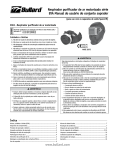
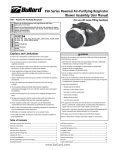
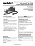
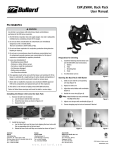
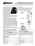
EVA Series Powered Air-Purifying Respirator
Blower Assembly User Manual
(for use with SparxLift Welding Helmets)
US-NIOSH
EVA1 - Powered Air-Purifying Respirator
Powered Air-Purifying Respirator with High Efficiency (HE) Filters Approval No. TC-21C-0940 (PAPRFC3)
Approval No. TC-21C-0941 (PAPRFC3)
Cautions and Limitations
A. Not for use in atmospheres containing less than 19.5% oxygen.
B. Not for use in atmospheres immediately dangerous to life or health.
C. Do not exceed maximum use concentrations established by regulatory standards.
F. D
o not use respirator if airflow is less than four cfm (115 lpm) for tight
fitting face pieces or six cfm (170 lpm) for hoods and/or helmets.
H. Follow established cartridge and canister change schedules or observe ESLI
to ensure that cartridges and canisters are replaced before breakthrough.
I. C ontains electrical parts that may cause an ignition in flammable or
explosive atmospheres.
J. Failure to properly use and maintain this product could result in injury or death.
L. F ollow the manufacturer’s user instructions for changing cartridges and/
or filters.
M. A ll approved respirators shall be selected, fitted, used and maintained in
accordance with MSHA, OSHA and other applicable regulations.
N. N
ever substitute, modify, add or omit parts. Use only exact Bullard
replacement parts in the configuration as specified by the manufacturer.
O. Refer to User’s Instructions and/or maintenance manuals for information
on use and maintenance of these respirators.
P. NIOSH does not evaluate respirators for use as surgical masks.
* At very high work rates, the pressure in the device may become negative
at peak inhalation flow.
� WARNING
• Always use genuine SparxLift front and inside cover plates. Failure to
do so may result in injury and will void the warranty.
• The SparxLift is not designed for overhead welding without the use of
additional protection.
• Check your helmet for physical damage and test it regularly. If your
helmet is damaged or is not working normally have it tested and
repaired before use.
• Always select the appropriate shade before use according to the type
of welding and current/amperes used. When in doubt refer to your
authorized safety representative.
EN175
EN379
ANSI Z87S
� WARNING
Use strictly in accordance with instructions, labels and limitations
pertaining to the EVA Series respirator.
1. The EVA Series respirator does not supply oxygen. Use only in
adequately ventilated areas containing at least 19.5% oxygen.
2. Do not use when concentrations of contaminants are immediately
dangerous to life or health (IDLH).
This term is defined in 29CFR 1910.134 (b).
3. Do not use these respirators for respiratory protection during
abrasive blasting or clean up.
4. Do not use in circumstances where the airborne concentration level
of contaminant exceeds maximum use concentration for this type of
respirator as established by regulatory standards.
5. Leave area immediately if:
• Breathing becomes difficult
• Dizziness or other distress occurs
• You taste or smell the contaminant
• Unit becomes damaged
• Battery alarm activates
• Low Flow alarm activates
6. This apparatus must not be worn with the blower unit switched off.
If the blower is switched off, a rapid build-up of carbon dioxide and
depletion of oxygen may occur, which could result in death or serious
injury.
7. Never alter or modify this respirator. Use only Bullard NIOSHapproved EVA Series components and replacement parts for this
respirator.
8. This device is not immune to highly powered RFI/EMI emissions.
Failure to follow these warnings could result in death or serious injury.
Table of Contents
Warnings, Cautions and Limitations (EVA)...................................................... 1
Component Diagram........................................................................................ 2
Principle of Operation and Battery Pack.......................................................... 3
Pre-Operational Inspection.............................................................................. 4
Mounting the Breathing Tube............................................................................ 4
Checking Air Flow............................................................................................. 4
Air-Purifying Elements..................................................................................... 5
Mounting and Replacing Filter/Cartridges....................................................... 5
Donning the Blower......................................................................................... 6
Low Battery Alarm........................................................................................... 7
Troubleshooting................................................................................................ 7
NIOSH Approval Label..................................................................................... 8
Welding Helmet Use....................................................................................9-11
Cleaning and Storage...................................................................................... 12
Cautions (Welding Helmet)............................................................................. 13
Ordering Information...................................................................................... 14
Warranty......................................................................................................... 15
www.bullard.com
Welding Helmet with Shroud
Component Diagram
Breathing Tube with Nomex Cover
Blower Unit with Battery and Belt
HE Filter with Spark Arrest Cover
PAHBTBK
Breathing TubeS
Helmet with Shroud
2
PA1BTXL - XL LENGTH
Cover with Spark
Arrest Filter
Blower and Battery
PA1BTXS - XS LENGTH
NMXBTC
EVA
EVABELT1
EVABELT2
Belts
Component Diagram
Breathing Tube Cover
PA1BT - STANDARD LENGTH
www.bullard.com
EVADCFR1
EVA Series Powered Air-Purifying Respirator
Blower Assembly User Manual
(for use with SparxLift Welding Helmets)
EVA Series - Principle of Operation
The EVA Series Powered Air-Purifying Respirator (PAPR) System is configured
in six parts:
1. The blower and belt assembly:
EVA1
Blower Unit
EVABELT1 Comfort/Decon Belt
PA1AFI
Air Flow Indicator
2. The battery pack (Part No. EVABAT1). One fully charged pack will power
the blower for approximately four to ten hours depending upon factors
such as speed, cartridge selected and cartridge loading.
3. The breathing tube, which is available in 4 options:
PAHBT
Powered Air Hood Breathing Tube Assembly
(standard length)
PAHBTXS
Powered Air Hood Breathing Tube Assembly
(short length)
PAHBTXL
Powered Air Hood Breathing Tube Assembly
(long length)
PAHBTBK
Powered Air Hood Breathing Tube Assembly
for Back Pack
4. The High Efficiency Particulate Absolute (HEPA) filter.
5. SparxLift welding helmet with Shroud.
To charge the battery pack, do the following:
• Press the battery release on the pack to remove the battery from the
back of the blower (see Figure 1).
Battery
release
Figure 1
Figure 2
• Place battery upside down into the charging port of the battery charger
(Figure 2).
• Connect the battery charger to a 110-volt AC electrical outlet.
• Charge the battery pack for approximately four hours.
6. The Battery Charger:
EVASMC
Quick charger (single port)
EVASMC2
Analyzing charger
EVAGC
Gang charger (six port)
The blower unit draws in ambient air through the filter. The purified air is
blown into the wearer’s hood through the breathing tube. A flow indicator
is provided to check that there is an adequate volume of air available to the
wearer prior to use. The system is designed to operate at a minimum air flow
of approximately seven cubic feet of air per minute (210 liters per minute)
in the hood under normal use on the standard speed setting, and eight and
one-half cubic feet of air per minute (241 liters per minute) in the hood under
normal use on the high speed setting. A feedback loop from the Mass Flow
Sensor to the impellor continually monitors and adjusts the air flow to keep it
constant at the design set point.
T he units are designed for use at temperatures from 23ºF to 122ºF (-5ºC
to 50ºC). A high temperature alarm will sound at 50ºC (122ºF).
The EVA Series Blower is equipped with two alarms: A 77db continuous
alarm will sound when the air flow falls below approximately 185 lpm and
a 77db intermittent chirp alarm will activate to indicate that the battery has
approximately 15 minutes of remaining capacity.
Battery Pack
Table-top gang chargers EVAGC with 6 ports are also available.
Diagnostic functions are available for chargers (upon special order) including
access to data such as number of cycles of operation, remaining charge
capacity, etc. Details for these functions are available in the EVASMC2
charger user manual (upon special order).
� WARNING
DO NOT charge batteries in hazardous areas.
Battery Storage
Storage of Li Polymer batteries is relatively easy. Unlike Nickel batteries, they
lose a very small amount of power (less than 0.5% per day) and therefore can
be charged and stored ready for use. If long-term storage is required, it is best
to store the battery in a cool place with at least 40% charge still remaining.
NOTE
Discharging and re-charging the battery fully at least once every 3
months is suggested to ensure the longest possible life of the battery.
Do not leave on the charger for more than 30 consecutive days.
To maximize battery life, these guidelines should
be followed:
• Remove the battery from the blower unit when not in use.
One fully charged battery pack will power the blower for approximately four
to eight hours depending upon factors such as speed selected, cartridge
selected and filer/cartridge loading.
NOTE
The battery has built-in short circuit protection. In the event of a short
circuit, an internal polyfuse will trip. The fuse will reset itself within 5-10
seconds allowing the battery to resume normal operation.
• Charge the battery before it is completely discharged. The low battery
alarm indicates that the battery needs to be charged. The battery is
designed with a circuit to protect the battery. It will not allow the battery
to be discharged below a safe voltage for the cells, regardless of airflow,
without the alarm sounding. When the battery reaches the voltage cutoff
it will automatically cease operation.
• Always charge the batteries at room temperature or cooler. At higher
temperatures, the battery pack may not accept a full charge. If the battery
www.bullard.com
Principle of Operation / Battery Pack
T he battery pack mounts in a compartment on the back of the blower. A fully
charged battery pack will power the blower for approximately four to ten
hours depending upon factors such as speed selected, cartridge selected, and
filter/cartridge loading.
While the battery is charging, the light on the charger will remain red. The
charger light will illuminate green when charging is complete.
3
Mounting the Breathing
Tube on the Blower
pack feels hot, let it cool for 30 minutes before charging.
• Do not charge battery packs
in an enclosed cabinet without
ventilation.
• Ensure that a rubber gasket is in
place in the breathing tube coupler on
the blower unit.
Battery Fuel Gauge:
EVA Battery Packs are equipped with
an on-board fuel gauge (Figure 3) to Figure 3
indicate the amount of remaining capacity left in the battery pack. To check the remaining capacity, simply depress
the button labeled “Push” and LEDs will illuminate indicating the level of battery
capacity remaining. When fully charged all four LEDs will illuminate green, and
when 25% or less charge is available a single LED will illuminate red.
• Screw one end of the breathing tube
into the blower unit - hand tight is
sufficient (Figure 5).
Pre-Operational Inspection
• Switch on the blower by pressing the on/off button for 1-2 seconds
confirmed by a short beep.
Prior to each work shift, perform the following Pre-Operational Inspection to
ensure proper operation and to ensure that the unit is completely assembled.
1. Belt Mounted Blower Unit, Part No. EVA1
• Check that the unit is clean and undamaged.
• Inspect for deterioration, physical damage and improper assembly.
2. Filter/Cartridges
• Inspect the filter/cartridge for any physical damage
• Check the label to ensure the filter/cartridge has not exceeded its “use-by” date.
• Inspect the gasket on the filter for any physical damage.
NOTE
Each filter comes with a permanent gasket.
• Ensure that the correct filter/cartridge is appropriate for the contaminant.
• Consult the NIOSH approval label and your own in-plant safety professional if
you have any questions as to the suitability and efficiency of the Air-Purifying
Element.
• Screw the cartridge into the port until hand-tight and the locking tab is secure (Refer to Mounting and Replacing
Filters on Blower Unit on page 5).
3. Battery Pack
• If the Low Battery Alarm sounds at this time, the battery needs to be recharged.
See instructions on page 2 regarding properly charging the battery.
• If the Low Flow Alarm sounds at this time, the
hood, breathing tube and filter should be check
for a blockage.
Checking Airflow with the Airflow
Indicator (PA1AFI)
With the blower switched ON and the filters/cartridges
mounted, take the free end of the breathing tube in one
hand, hold it upright and place the Airflow Indicator
into the end of the tube (Figure 6).
Figure 6
Apply a light downward pressure to the Airflow
Indicator to get a reasonable seal at the breathing tube
end. Ensure that the air outlet holes in the Airflow Indicator tube are not
blocked. Two hands may be used if preferred, one to hold the breathing tube
and one to hold the Airflow Indicator.
The position of the ball in the Airflow Indicator should be observed. If any
part of the ball is below the PASS LINE on the Airflow Indicator, check for:
• Blower malfunction.
If the ball is completely above the PASS LINE on the Airflow Indicator, then
the system is ready for use.
• Place the battery pack in the battery
compartment on the blower.
Pre-Operational Inspection
Figure 5
• Low battery or battery malfunction.
• Check the Fuel Gauge to determine
sufficient charge is available.
4
• Ensure that the ON/OFF Switch is in
the OFF position.
• Clogged or damaged Air-Purifying filter elements on the HE filter. See
“Mounting and Replacing Cartridges on the Blower Unit” on page 7.
• Check that the battery is not damaged.
• The battery tab should click when
completely engaged (Figure 4).
• Ensure that neither the breathing tube
nor the filter is blocked.
� WARNING
Figure 4
If the blower malfunctions during use in a hazardous area:
4. Helmet with Shroud (SLS1 or SLS2)
• Inspect both the helmet and the shroud for any physical damage
• Inspect shroud to helmet velcro attachment and ensure proper
installation.
• To provide a general check of system status you may wish to set the
shade control to 11 and hold the helmet towards a bright incandescent
light source. Under normal circumstances the filter will change from light
to dark state and back to light state again as you move the helmet away.
Remain calm and LEAVE the hazardous area immediately.
DO NOT use a blower that fails the flow test (air flow indicator sold separately).
Use ONLY Bullard filter/cartridges which comply with and have the
NIOSH approval label and which are appropriate for the contaminant.
Failure to observe these warnings could result in death or serious injury.
www.bullard.com
EVA Series Powered Air-Purifying Respirator
Blower Assembly User Manual
(for use with SparxLift Welding Helmets)
Locking
tab
EVA Series PAPR Air-Purifying Elements
Principle of Operation
The following filter/cartridge protection classification applies when used with
any of the hoods or loose fitting facepieces.
NIOSH Filter/Cartridges
Protection
High Efficiency (particulate)
Protection
EN12941 P3
Filter/Cartridge
PAPRFC3
NIOSH / ANSI Color Code
Magenta
EN Filter/Cartidges
Filter/Cartridge
PAPRFC3
Color Code
White
HE particulate filters are 99.97% effective against all particulate aerosols.
Filters are supplied in quantities of six per box.
Figure 8
Figure 9
Installing the Spark Arrest Cover
If using the HE filter (PN PAPRFC3) and waist belt, then use the EVADCFR1 dust
cover and spark arrest cover. Or if using a back pack use the EVABPDCFR1.
Another option is to use the PAPRSC2 shower/spark cap to protect the filter and
the NMXBTC to protect the breathing tube.
Insert the blue mesh disc into the cover, laying the disc against the plastic
perforated disc.
With the breathing tube attached to the blower but not the helmet, slide the
cover down the tube.
� WARNING
Use only the filter/cartridge(s) described in the above table.
Do not change filter/cartridges while in a hazardous atmosphere.
Incorrect filter/cartridge selection will invalidate all performance
statements and approvals for this equipment.
Failure to follow these warnings could result in death or serious injury.
*DO NOT fit filters directly to the hood.
Then wrap the ends of the cover around the blower and secure with the
plastic snaps.
The Nomex fabric will protect the breathing tube and the blower while the
mesh will protect the HE filter material.
Installing and Removing the Belt on the
Blower Unit
Mounting and Replacing Filters
on the Blower Unit
To Install the Belt
• With the blower filter side down, orient the lever locks as shown in Figure 10.
• Lay belt over blower as shown in Figure 11.
• Rotate level locks until they are oriented as shown in Figure 12.
High efficiency particulate filters must be replaced when retained particles
clog the filters and reduce air flow below acceptable levels, as indicated by
testing with the Air Flow Indicator as described at left (Figure 7).
To Remove the Belt
• With the blower filter side down, orient the lever locks as shown in
Figure 13.
To Replace Filters
• Remove the air-purifying element
from its packaging, and inspect for
damage. If in doubt do not use.
• Check that the air-purifying element
has not exceeded its “use-by” date.
• Check that the filter connecting
thread and gasket are in good condition.
• Remove belt from blower.
Figure 7
• Check that the air-purifying element is appropriate to the hazard. If in
doubt consult your respirator program administrator or supervisor.
Figure 10
Figure 11
Figure 13
Figure 14
Figure 12
• Check that the threads in the blower unit port are in good condition and
clear of contaminant.
• Check to see that the locking tab is secure (see Figure 9).
NOTE
Plastic insert may be removed for cleaning as shown in Figure 13-14.
See back page for more information on cleaning.
www.bullard.com
Air-Purifying Elements
• Screw the air-purifying elements into the receptacles (see Figure 8) until
the cartridge is hand tight. DO NOT OVERTIGHTEN.
5
Donning the Blower and Respirator
Final Donning:
on/off switch
• Attach the other end of breathing tube to
blower unit (if not already attached) by
screwing adapters together.
Initial Donning
Prepare to don the blower, battery and hood in a safe, hazard-free area and
do the following:
• Ensure that the filter/cartridges used are suitable for the contaminant in
question and are compatible with the EVA1 Blower Unit.
• Remove any protective film covering the
lens of the headpiece.
• Place the battery in the battery compartment on the back of the blower.
Figure 15
• Put on the belt and blower assembly and
make any final adjustments to the belt
as necessary, keeping the breathing tube and helmet behind the head.
• Fit the blower and belt around the user’s waist and adjust the belt for a
comfortable fit (suspenders are also available).
• Turn the blower on by depressing and holding the on/off switch (Figure
16) for approximately 1 second indicated by a short beep.
• Remove the belt and blower to install the helmet and corresponding
breathing tube.
• Buckle the belt onto the waist (blower unit should be in the lower back
of the wearer).
• Check that the filter/cartridge is properly mounted on the blower unit.
• Don the helmet.
� WARNING
• Choose speed setting (see below).
The use of any filter/cartridge not approved with the EVA1 blower unit
may put the user at risk and could result in death or serious injury.
• Place the helmet on the head making any final adjustments to the fit as
required at this time to ensure a comfortable and stable fit.
Connecting the Breathing Tube to the Helmet
Final Donning
With the shroud already installed into the helmet, thread the end of the
breathing tube that is not already connected to the blower to the threaded
port at the rear of the shroud until finger tight.
� WARNING
Do not put on or remove these respirators in a hazardous atmosphere
except for emergency escape purposes. Failure to heed these warnings
could result in death or serious injury.
Donning the Respirator Assembly
Buckle the blower with the belt onto the waist with the blower in the lower
back of the wearer.
Adjust for comfort as preferred.
Turn the blower on by depressing and holding the on/off switch (Figure 15)
for approximately 1 full second (indicated by a short beep).
Don the helmet with shroud.
Speed Selection
For the SLS1 shroud:
• Insert your chin into the shroud and pull the helmet upward toward
the face.
The EVA1 Blower is equipped with the ability for the user to select one of two
speeds for operation.
• Adjust the drawstring for a snug, but comfortable fit.
When the unit is initially turned on, the blower will operate at approximately
8.5 cfm = 240 lpm (high speed). Note: The battery life is reduced at the
higher speed.
For the SLS2 shroud:
• Widen the turtleneck with your hands and insert your head, chin first,
then pull onto your head.
• Adjust drawstring for snug fit.
Donning the Blower
• Adjust the ratchet assembly and harness for angle and comfort.
6
• Adjust the speed if desired.
Pressing the on/off switch will change the speed to approximately
7 cfm = 198 lpm (low speed).
Pressing the on/off switch additional times will toggle the unit between the
two speeds.
� WARNING
Do not enter a hazardous area until you are sure that the blower and
hood are fully operational and the blower is running. The user should
periodically leave the hazardous area to check the airflow through the
system. If the low battery or low flow alarm should sound, or if the user
experiences any difficulty in breathing, or senses any taste or any odors
from the hazard, the user should leave the hazardous area immediately.
Failure to observe these warnings could result in death or serious injury.
NOTE
Speed change is confirmed by a short beep.
Replacing the SLS1 Shroud
• Remove the old shroud by pulling carefully along the velcro mating line.
• To install the new shroud, start at the top of the helmet and match the
loop sections of Velcro on the shroud to the corresponding hook
selections of Velcro on the helmet and secure with pressure.
www.bullard.com
EVA Series Powered Air-Purifying Respirator
Blower Assembly User Manual
(for use with SparxLift Welding Helmets)
• Wrap the padded ratchet cover around the ratchet knob and secure the Velcro.
• Wrap the 5/8” Velcro strips on each side of the ratchet around the
headband and secure.
Replacing the SLS2 APF Shroud
• Remove the old shroud by pulling carefully along the velcro mating line.
• To install the new shroud, start at the top of the helmet and match the
loop sections of Velcro on the shroud to the corresponding hook sections
of Velcro on the helmet and secure with pressure.
Low Battery Alarm and Low Flow Alarm
The EVA1 Blower unit is equipped with a Low Battery Alarm and a Low Flow Alarm.
The Low Battery Alarm will sound an intermittent 77 dba electronic beep
indicating that there are approximately 15 minutes of remaining battery capacity.
The delays between beeps will get shorter and shorter as time runs out.
The Low Flow Alarm will sound a continuous 77 dba electronic beep indicating
that the flow to the hood has dropped below the design specification of 185 lpm
= 6.5 CFM (Note: The NIOSH minimum required flow is 170 lpm = 6 CFM).
When either of these alarms sounds, the user should immediately do
the following:
• Leave the hazard area
• Remove the helmet
•Disconnect the breathing tube from the hood
•Check the airflow with the airflow indicator (see page 4).
If the airflow indicator indicates insufficient airflow, the battery should be
fully charged (see “Battery Pack” on page 3), and/or the filter/cartridge
should be replaced.
NOTE
The EVA1 blower is provided with a circuit to protect the battery. It will
not allow the battery to be discharged below a safe voltage for the cells,
regardless of airflow, without the Alarm sounding. When the battery
reaches the voltage cutoff it will automatically cease operation. When
the Low Battery Alarm sounds and the filter cartridges are not clogged,
the battery should be recharged to protect the battery and thereby
prolong the working life of the unit. If the ball in the Airflow Indicator
is BELOW or PARTLY BELOW the PASS LINE with a fully charged battery,
the filter cartridges may need to be changed.
Doffing the Respirator
Prepare to doff the blower, battery and helmet in a safe, hazard-free
area and do the following (in conjunction with your employer’s standard
operating procedures):
• Remove the helmet.
• Turn the blower off by holding down the on/off switch for 5 seconds. This
is confirmed by a long beep and a shut down of the motor.
• Remove the waist belt.
• Disconnect the helmet from the breathing tube.
• Disconnect the breathing tube from the blower.
• Clean and inspect components as necessary.
• Place battery on charger (as desired).
•Check the operation of the low-flow alarm by blocking the end of the
breathing tube. The device will first ramp up to compensate and if correct
flow cannot be achieved, the alarm will sound within 5 seconds.
• Place components in storage.
� WARNING
The use of any filter/cartridge not approved with the EVA1 blower unit
may put the user at risk and could result in death or serious injury.
Troubleshooting
The following guide will assist you in troubleshooting to locate possible issues with your respirator:
Circumstance
Possible Cause(s)
Solution
Move to a cooler location
Low Battery Alarm is sounding
Low Voltage
Charge the battery
Blower malfunction
Return blower for analysis
Clogged/damaged air-purifying filter element
Replace the filter/cartridge
Battery Low
Re-charge the battery
Blower malfunction
Leave hazardous area immediately and check equipment. If the
problem persists and no damage is found, return equipment for repair.
Replace breathing tube and/or hood.
Hood neck cuff is restricting flow
Adjust neck cuff position
Equipment damaged
Leave hazardous area immediately and check equipment
Non-particulate hazard
Select appropriate filter cartridge
Low airflow
Leave hazardous area immediately and check equipment
If the problem persists and no damage is found, return equipment
for repair
Damaged Battery
Return battery for analysis
Malfunctioning Battery Charger
Return charger for analysis
Hood neck cuff is restricting flow
Adjust neck cuff position
Low Flow Alarm is sounding
Smell or taste contaminant
Blower unit does not run full
service life
www.bullard.com
Low Battery Alarm / Troubleshooting
High Temperature Alarm is sounding High Temperature ≥ 122ºF (50ºC)
7
Bullard
1898 Safety Way
Cynthiana, KY 41031-9303
877-BULLARD (285-5273)
MODEL SPARX LIFT RESPIRATOR
Approved Only in the Following Configurations:
X
X
X
X
X
X
X
X
X
X
X
X
EVASMC2
X
X
EVABPDCFR1
X
X
PAPRPF2
X
X
EVADCFR1
X
X
EVAGC
X
X
PAPRSUSP1
X
X
PAPRSC2
EVABELT2
X
X
PA1AFI
EVABKPK1
X
X
NMXBTC
BATTERY
EVABELT1
X
X
EVASMC
FILTER ASSEMBLY
EVABAT1
X
X
CAUTIONS AND
LIMITATIONS2
ACCESSORIES
EVAEXT1
BLOWER UNIT ASSEMBLY
X
X
EVA1
X
X
BELT
ASSEMBLY
PAPRFC3
X
X
PAHBTXL
X
X
PAHBTBK
X
PAHBT
X
ALTERNATE
BREATHING
TUBES
PAHBTXS
ALTERNATE SHROUD
X
X
SLS1
HE
HE
SLS2
PROTECTION1
21C-0940
21C-0941
SLH
TC-
HELMET ASSEMBLY
RESPIRATOR COMPONENTS
X ABCFHIJLMNOP
X ABCFHIJLMNOP
1. PROTECTION
HE = High Efficiency Particulate Air Filter for Powered Air Purifying Respirators
NIOSH Approval Label
2. CAUTIONS AND LIMITATIONS
8
A. Not for use in atmospheres containing less than 19.5% oxygen.
B. Not for use in atmospheres immediately dangerous to life or health.
C. Do not exceed maximum use concentrations established by regulatory standards.
F. Do not use this respirator if airflow is less than four cfm (115 lpm) for tight-fitting facepieces or six cfm (170 lpm) for hoods and / or helmets.
H. Follow established cartridge and canister change schedules or observe ESLI to ensure that cartridges and canisters are replaced before breakthrough occurs.
I. Contains electrical parts which have not been evaluated as an ignition source in flammable or explosive atmospheres by MSHA / NIOSH.
J. Failure to properly use and maintain this product could result in injury or death.
L. Follow the manufacturer’s instructions for changing cartridges and / or filters.
M. All approved respirators shall be selected, fitted, used and maintained in accordance with MSHA, OSHA and other applicable regulations.
N. Never substitute, modify, add or omit parts. Use only exact replacement parts in the configuration specified by the manufacturer.
O. Refer to User’s Instructions, and/or maintenance manuals for information on use and maintenance of these respirators.
P. NIOSH does not evaluate respirators for use as surgical masks.
www.bullard.com
EVA Series Powered Air-Purifying Respirator
Blower Assembly User Manual
(for use with SparxLift Welding Helmets)
PAPR Cleaning
Instructions for use of the SparxLift
Welding Helmet
� WARNING
Avoid contaminant entry into the breathing tube, as this will compromise
respiratory protection and could result in death or serious injury. Consult
your local safety professional if you suspect that contaminant has
entered the breathing tube.
When cleaning the equipment, do the following:
• Ensure water does not enter filter. Replace wet filter.
• DO NOT use gasoline, organic-based solvents, or chlorinated degreasing
fluids (such as trichloroethylene), as they will cause damage.
• DO NOT immerse the equipment in water or other cleaning fluid,
as this may cause contamination in the breathing tube and blower
interior that will be difficult to remove.
• Use a lint-free cloth moistened in a mild solution of soap and warm
water to clean the outer surface of the equipment.
Failure to observe the instructions and warnings in this manual
invalidates all performance statements and approvals for this equipment
and could result in death or serious injury.
The following chemicals have been tested and approved as cleaning agents
for the blower housing, belt and battery:
A. Process NPD (1.256) from Steris
B. Spor Klenz (undiluted) from Steris
C. Clorox liquid bleach at 10% concentration
D. Sani-Cloth HB wipes
E. 100% Methanol
F. 70% IPA
Once filter/cartridges have reached the end of their useful life, discard in
accordance with federal, state, and local guidelines, and in conformance with
plant safety regulations.
PAPR Maintenance
DO NOT open the PAPR Housing Assembly. Internal repairs should only be
preformed by authorized personnel at the manufacturer’s facility. The user
should inspect the PAPR before each use. Contact Bullard at 877-BULLARD or
[email protected] for any questions.
PAPR Storage
When the blower is completely dry, store in a clean, dry area, away from
direct sunlight and sources of direct heat.
The storage temperature should be between 32ºF to 90ºF (0ºC to 32ºC) with
humidity less than 90% RH.
Thank you for purchasing SparxLift welding helmet.
NOTE
For your own protection, safety and to ensure the maximum service
life of your new helmet please read this manual carefully before use.
Misuse or abuse may result in injury or reduced protection and may also
void your warranty.
Before Use
The auto darkening welding filter in the SparxLift has been designed for arc
welding and gas cutting. It is suitable for all normal arc welding processes
such as MIG, MAG, TIG, SMAW, Plasma Arc and Air Carbon welding.
Before use the shade control should be adjusted to the appropriate level
based upon EN169 (European Standard specifications or equivalent) or other
appropriate safety guidelines. When in doubt please consult your safety
representative or your authorized Bullard distributor.
The SparxLift provides continuous protection from ultraviolet and infrared
radiation to the maximum level indicated on the product and as described in the
relevant Standards. This protection is fail-safe and is not compromised by loss
of battery power or other electronic failure.
The SparxLift welding filter cartridge is fitted with two independently operated
sensors that detect the welding arc and respond accordingly resulting in the
appropriate darkened filter state as set by the user and as indicated on the
scaled adjustment. Please note that professional judgement may be required
to achieve the best results. When in doubt consult an authorized safety
representative or your Bullard distributor and always maintain a conservative
attitude towards operation.
Two replaceable lithium batteries type CR2032 (3V) are used as major power
sources. An additional solar cell panel extends battery life and ensures
efficient operation. When operating normally the welding helmet will switch
on automatically and switch off automatically to save power a few minutes
after the last welding arc has been detected.
To provide a general check of system status you may wish to set the shade
control to 11 and hold the helmet towards a bright incandescent light source.
Under normal circumstances the filter will change from light to dark state
and back to light state again as you move the helmet away. Please note that if
you have any questions or there is any doubt about the performance of your
Bullard product you should refer to your authorized safety representative or
Bullard distributor.
NOTE
• Always use genuine SparxLift front and inside cover plates. Failure to do
so may result in injury and will void the warranty.
• The SparxLift is not designed for overhead welding without the use of
additional protection.
• Always select the appropriate shade before use according to the type of
welding and current/amperes used. When in doubt refer to your authorized
safety representative.
www.bullard.com
Welding Helmet Use
• Check your helmet for physical damage and test it regularly. If your helmet is
damaged or is not working normally have it tested and repaired before use.
9
Helmet and Head Harness Adjustment
Solar Cell Power Saver
Please make the appropriate adjustment(s) to the head harness to ensure a
comfortable and secure fit. It only takes a minute and helps ensure you are
properly protected. The SparxLift harness allows you to adjust the distance
and angle between your eyes and the filter window. You can also adjust the
circumference of the headband to ensure a comfortable but firm fit. Please
make these adjustments before use based on the illustrations in figures
shown below.
The SparxLift solar cell array minimizes battery use by supplying continuous
power during welding. The optimized auto on/off power management circuits
ensure stable performance and maximum battery life under all conditions.
Dual Sensors Plus Pre-Shading
Z-Slide cartridges incorporate the latest advances in sensor and preshading technology. By sensing FR and using specially programmed circuits the
Z-Slide responds reliably under the most demanding conditions. From Low
amp TIG work to simple stick welding, the Z-Slide can be depended upon to
respond reliably every time and with the Brilliant Clear X-View screen, welding is now even easier and more enjoyable.
Brilliant Clear X-View Technology
Markings
The appropriate available shade number markings and range are indicated
on the product. Please ensure that the appropriate shade number is selected
before welding. Used properly the SparxLift provides eye and face protection
to meet or exceed EN379 and EN175 and other relevant Standards where
indicated. The following example illustrates these requirements. Please note
this example is provided for illustration purposes only.
Light Shade
By incorporating the best optically correct UV and IR filters with special
ultra-fast low-distortion LCD panels the SparxLift has made a quantum leap in
filter clarity and performance. When combined with the proprietary electronic
control technology the results are simply amazing. Blazingly fast, beautifully
clear and extremely stable the SparxLift series cartridge sets new industry
standards in performance, protection and control.
Shade Control
The required filter dark state can be selected by using
the shade control. The SparxLift can be adjusted between
shades 9 to 13 with the embossed arrow on the dial
indicating the current adjustment. Always use the appropriate shade for the welding operation you are undertaking. When in doubt please consult the relevant
Standards or your authorized safety representative.
CE 4
Dark Shade
9-13
Manufacture Identification
SERVORE*
Optical Class
1
Diffusion of Light Class
1
Variations in Luminous Transmittance Class
1
Certification Mark of Number of Standard
379
Recommended shade numbers according to BS 679, DIN 4647-1 and EN169
Current in amperes
Welding
Process
0.5
2.5
1
10
5
20
15
40
80
30
60
9
10
125
100
175
150
225
200
275
250
350
300
450
400
500
*SEVORE manufactures the helmet for Bullard
Covered
Electrodes
Technical Specifications
Switching time (light-dark)
Welding Helmet Use
Shade Level
10
1/25,000(0.04msec)
Inactivated
Shade #4
Activated
Shade #9 ~ #13
Sensitivity Adjustment
Dual sensors plus pre-shading (Low-High)
Switching Delay (dark to light)
Adjustable 0.05s – 0.8s
Tig rating
RF(H) >1Amp / RF(L) >10Amp
Power supply
3V Lithium battery (CR2032) 2ea (replaceable)
Battery life
3000 hours (Approximately)
Supplementary power
Solar cells (Auto On/Off)
Battery replacement
Replaceable (Low battery indicator)
Cartridge size
110×90mm (4.3×3.5 in)
Filter window
97×46mm (3.8×1.8 in)
Total weight
Autolift : 610g (21.5 oz)
Operating temp.
-5°C℃~ +55°C℃
Storage temp.
-20°C℃~ +70°C℃
11
MIG on heavy
metals
10
11
MIG light alloys
10
11
12
12
13
TIG on all metals
and alloys
9
10
11
MAG
10
11
12
Arc-air
gouging
Microplasma
arc welding
11
11
4 5 6 7 8 9
10
11
12
13
14
12
13
14
13
12
14
13
12
13
14
15
14
13
10
Plasma jet
cutting
12
14
15
15
13
14
15
According to the conditions of use, the next greater or the next smaller scale
number can be used.
www.bullard.com
EVA Series Powered Air-Purifying Respirator
Blower Assembly User Manual
(for use with SparxLift Welding Helmets)
Maintenance
Delay Control
The delay functions should be used to set the
recovery delay from dark to light of the welding
filter according to welding method and current.
NOTE
Always ensure that all maintenance procedures are conducted in a
clean dry place. Use clean dry hands and avoid direct contact with any
glass surfaces. Handle cover plates and welding filter by the edges and
carefully clean off any dirt or debris before re-use.
Changing the Front and Rear Cover Plates
Control Function
• Unclip and open the front cover as shown in the diagram. You will then
be able to remove and replace the front cover lens as required.
• Before installing the new cover lens remove the protective film from both sides.
• To change the rear cover lens gently remove the cartridge from the
helmet you will then be able to unclip the inner cover lens and replace it.
Again, you must remove the protective film from both sides of the cover
lens before installing it.
Parts
1. Solar Cell Panel
2. Sensor
3. LCD Filter Plate
4. Shade Control
5. Delay Control
6. Sensitivity Control
7. RF Sensor Switch
8. Low Battery Indicator
Light Sensitivity Control
Where problems are encountered during
welding at low amps (e.g. TIG) or there is a
high level of ambient light please follow these
steps. First try adjusting the sensitivity control
switch. Start with the sensitivity LOW (gently
turn anticlockwise until the knob stops) and
adjust upwards as required. If this does not
solve the problem, set the sensitivity control
in the middle position and hold the helmet close to the target object and
adjust the shade control completely clockwise. If the welding filter stays in
the light state, leave the control set at this point. If the filter switches to the
dark state, turn the shade adjustment back until the filter just switches into
the light state. The filter should now be adjusted correctly. If the welding
filter still does not respond appropriately, please adjust the sensitivity control
again (having previously adjusted the shade control as explained above).
[To achieve optimum results in very unusual circumstances you may need to
perform this process again having first reset the sensitivity control to low.]
RF Sensor
Tig Rating
RF HIGH
>1 Amp
RF LOW
>10 Amp
Always use genuine Bullard parts. Never use a welding helmet without
both front and rear cover lenses installed.
Changing the battery
• The SparxLift uses two 3V lithium Ion batteries (CR2032) as a main power source. These batteries are user replaceable and should be replaced immediately when
the battery warning light comes on and/or at least every three years. Always
replace both batteries at the same time with brand new batteries. Never install
previously used batteries in your helmet.
• To replace the batteries slide out the battery holders from either side of
the cartridge and discard the old batteries. Install the new batteries in
the battery holders and slide the battery holders back into the cartridge.
NOTE
Always note the polarity of the batteries and install them as shown in
the diagram and as marked. Batteries rely on good electrical contact to
function properly and so always use clean dry hands and avoid getting
dirt inside the cartridge when exchanging batteries.
www.bullard.com
Welding Helmet Use
New RF High/Low switch for even better RF sensitivity
control. Switch to high for extremely low amp TIG(down
to 1 amp) or when using shielded cables and welders.
Switch to low when working near other welders or in
areas of high RF interference to avoid false triggers and
for general welding.
NOTE
11
Changing the Inner Cover Plate on the SparxLift
• From inside the helmet unclip the installed cover plate from the shell noting
the locking tags on either side of the helmet (see diagram).
• Remove the film from both sides of the new cover plate and then insert
first one side and then the other into the relevant slots on each side of
the helmet.
NOTE
Always check to ensure that the locking tags on each side of the helmet
are properly mated with the slots in the cover plate and that the four
raised guides on the helmet shell are located in the matching slots in
the cover plate.
Maintaining the Auto Lift assembly on the SparxLift
• Assembling and disassembling the Auto Lift assembly on the SparxLift is
a simple process but should be done according to the following instructions
to ensure problem free operation of the helmet.
• Locate the spring (10-3L) in the recess on the outside of the helmet shell
ensuring that the end of the spring is hooked into the hole provided and
pointing upwards. Springs are handed (R/L) and if reversed the Auto Lift
mechanism will not work.
• Place the spring retainer (10-2L) over the spring and ensure that the
tongue of the retainer is located in the slot provided on the side of the
helmet shell.
Storage and Temperature Range
Your Bullard welding helmet is strong and durable. It is designed to work
in temperatures between -5C and +55C. Do not use your helmet in very hot
conditions where temperatures exceed +65C. Always store your helmet in a
clean dry place out of the direct sun and protect it from exposure to moisture
or extreme heat (min/max storage temperature is -20C ~ +70C).
Avoid unnecessary impact or compression of your helmet and never use a
helmet that is damaged. Your Bullard welding helmet is a quality professional
tool and careful storage will extend the life of your investment.
Inspection
Check your helmet shell and filter on a regular basis when in normal use and
after extended periods of storage. Never use a cracked or damaged helmet
as this may result in personal injury and will void your warranty. Please
replace any worn or damaged parts as necessary. Genuine Bullard replacement
parts are available from your authorized Bullard distributor.
Cleaning
• Mount the cartridge holder assembly over the spring retainer ensuring that
the notches in the top of the spring retainer are nested into the matching
slots on the cartridge holder assembly.
• Insert the slotted bolt into the hole and over the end of the spring.
After removing the welding filter from the shell the shell can be cleaned
using a mild detergent and water solution. Sweat bands can be washed. A
silicone based lubricant may be used on moving parts if necessary but is not
normally required. The filter may be carefully wiped with a cloth dampened
with household window cleaning solution. Please be careful not to scratch
or otherwise damage the filter cartridge with fragments of welding spatter
or other abrasive dirt. Refer to the relevant parts diagram for illustrations
regarding assembly and disassembly.
• While holding the slotted bolt in place with your thumb, look inside the
shell and locate the black washer over the end of the bolt which should
now be visible on the inside of the shell. Note that the black washer has
internal fins that mate with the end of the slotted bolt.
• Insert the self tapping screw into the washer and screw it in. Avoid
over-tightening.
NOTE
Never expose the filter cartridge to direct contact with water or solvents.
Cleaning and Storage
• Use a coin to tension the springs on each side by turning the head of the
slotted bolts with a coin. Avoid over tensioning. Test the Auto Lift mechanism
after each adjustment. Usually turning the screw a few ‘clicks’ or about 180
degrees gives perfect results.
12
www.bullard.com
EVA Series Powered Air-Purifying Respirator
Blower Assembly User Manual
(for use with SparxLift Welding Helmets)
� CAUTIONS
• The SparxLift is designed for personal eye and face protection from harmful radiation, sparks and welding spatter produced under normal welding conditions. Please follow good industry and safety practices and use additional protection where necessary.
• Cover plates are strong and of industry standard quality but they are breakable. The SparxLift is a quality welding helmet but is not designed to provide
protection from severe impact such as broken grinding wheels or debris from other broken tools, corrosive liquids, explosions, or other extreme incidents.
We recommend you always adopt a conservative attitude towards safety and take additional precautions as required and recommended in the relevant
safety standards relating to the operation you are undertaking.
•The welding filter is not designed to be waterproof. Please do not use your helmet in the rain or other inclement weather. To do so may reduce the life of
your helmet and result in damage or injury.
• In the event that your helmet or welding filter is exposed to direct contact with, or is submerged in water or other liquid immediately stop using the
helmet, remove the filter cartridge from the shell, remove the batteries from the filter, inspect carefully for damage and if necessary mop-up excess
moisture with a paper towel and then leave to dry in a warm (not hot) place out of direct sunlight. Never place your helmet in an oven or microwave
to dry. Before use perform all normal system checks and if in any doubt contact your Bullard distributor. Your Bullard helmet is a precision engineered
professional protection product and must be maintained in good condition to ensure your personal protection.
• When working in the vicinity of other welders it is necessary to adopt good industry standard practice and ensure a minimum distance of 1M between
workers. Failure to do so may result in injury or malfunction of the auto darkening mechanism.
• Please do not wear the helmet when you are not welding. In some circumstances the auto darkening mechanism may be unexpectedly triggered resulting in
reduced vision and subsequent injury to yourself or others.
• Bullard does not support the use of SparxLift range of products in combination with any other manufacturers’ products. To use parts that are not
approved by Bullard may void your warranty and result in personal injury. Please use only genuine SparxLift parts and spares as provided by your authorized
Bullard distributor.
• Bullard reserves the right to make improvements, change or otherwise modify the specifications, materials and design of any and all Bullard products
at their sole discretion with a view to ensuring continuous improvement. Never attempt any unauthorized modifications or alterations to your Bullard
product. To do so may result in personal injury and void your warranty.
Thank you for purchasing a Bullard product. If you have any questions regarding this or any other Bullard product please contact your authorized Bullard distributor.
Cautions
www.bullard.com
13
Ordering Information
Respirator Assemblies (includes blower, battery, charger,
breathing tube, breathing tube cover, spark arrest cover, helmet,
shroud, and HE filter)
EVASLS1
EVASLS2
Loose-Fitting Facepiece Shroud System
Hood Style Shroud System
Blower Assemblies
EVA1
EVA2
EVA3
Blower Unit Only
Blower Unit, Battery, and Charger
Blower Unit, Battery, Charger, and HE filter
Lithium Polymer Battery Back (black)
Single Port Charger
Single Port Analyzing Charger
Six Port Gang Charger
Replacement Filter Cartridges
PAPRFC3
Replacement Shrouds
SLS1
SLS2
HE Particulate Filter (6 per box)
Loose-Fitting Facepiece Shroud
Hood Style Shroud
Replacement Breathing Tubes and Covers
PAHBT
PAHBTXS
PAHBTXL
PAHBTBK
EVADCFR1
EVABPDCFRI
NMXBTC
EVABELT1
Foam Closed Cell Comfort Bell
EVABELT2
Urethane Decon Belt
EVAEXT1
Belt Extenders
PAPRSUSP1Suspenders
EVABKPK1
Back Pack
Replacement Air Flow Indicator
Replacement Batteries and Chargers
EVABAT1
EVASMC
EVASMC2
EVAGC
Replacement Belts, Back Packs, and Suspenders
Powered Air Hood Breathing Tube Assembly
(standard length)
Powered Air Hood Breathing Tube Assembly
(short length)
Powered Air Hood Breathing Tube Assembly
(long length)
Powered Air Hood Breathing Tube Assembly
for Back Pack
Spark Arrest/Dust Cover, Fire Retardant for use
with PAPRFC3
Spark Arrest/Dust Cover, Fire-Retardant for use
with Back Pack and PAPRFC3
Nomex Breathing Tube Cover
PA1AFI
1. SLSHELLBLU
2. SLGL
3. SLRCL
4. SLADF
5. SLPBA
6. SLHCA
7. SLHG
8.SLBAT1
9. SLCLP
10. SLFCL
Ordering Information
Exploded View Diagram
14
Air Flow Indicator, Rotometer
Replacement Welding Helmet Parts
www.bullard.com
Helmet Shell, does not include harness or knob set
Inner Protective Lens (Grinding), 3 pack
Inside Cover Plate, 5 pack
Auto Darkening Filter
Push Button Assembly
Hinge Cap Assembly
Head Gear (including harness and knob set)
Battery
Lens Cover Pack (five front lenses, two inner lenses)
Front Cover Lens, 10 pack
EVA Series Powered Air-Purifying Respirator
Blower Assembly User Manual
(for use with SparxLift Welding Helmets)
One Year Limited Warranty
Return Authorization
Bullard warrants to the original purchaser that the EVA Powered Air-Purifying
Respirator and Helmet will be free of defects in material and workmanship
under normal use and service for a period of one (1) year from the date of
purchase. Bullard’s obligation under this warranty is limited to repairing or
replacing, at its option, articles that are returned within the warranty period
and that are, after examination, shown to Bullard’s satisfaction to be defective, subject to the following limitations;
The following steps must be completed before Bullard will accept any
returned goods. Please read carefully.
a) EVA Powered Air-Purifying Respirator and SparxLift Helmet and Shroud
must be returned to the Bullard factory with shipping charges prepaid.
b) EVA Powered Air-Purifying Respirator and SparxLift Helmet and Shroud
must not be altered from its original factory configuration.
c) EVA Powered Air-Purifying Respirator and SparxLift Helmet and Shroud
must not have been misused, subjected to negligent use, or damaged
in transport.
d) The date of purchase is within the one year warranty period. (A copy of
the purchaser’s original invoice showing the date of purchase is required
to validate warranty coverage.)
In no event shall Bullard be responsible for damages for loss of use or other
indirect, incidental, consequential or special costs, expenses or damages
incurred by the purchaser, notwithstanding that Bullard has been advised of
the possibility of such damages.
ANY IMPLIED WARRANTIES, INCLUDING WARRANTIES OF MERCHANTABILITY
AND FITNESS FOR A PARTICULAR PURPOSE, ARE LIMITED IN DURATION TO
ONE (1) YEAR FROM THE DATE OF PURCHASE OF THIS PRODUCT.
Some states do not allow the exclusion or limitation of incidental or consequential
damages, or allow limitations on how long an implied warranty lasts, so the above
limitations or exclusion may not apply to you. This warranty gives you specific legal
rights, and you may have other rights which vary from state to state.
Follow the steps outlined below to return goods to Bullard for repair or
replacement under warranty or for paid repairs:
1. Contact Bullard Sales Support by telephone or in writing at:
Bullard
1898 Safety Way
Cynthiana, KY 41031-9303
Toll-free: 877-BULLARD (285-5273)
Phone: 859-234-6616
In your correspondence or conversation with Sales Support, describe
the problem as completely as possible. For your convenience, your
sales support specialist will try to help you correct the problem over
the phone.
2. Verify with your sales support specialist that the product should be
returned to Bullard. Sales Support will provide you with written permission and a return authorization number as well as the labels you will
need to return the product.
3. Before returning the product, decontaminate and clean it to remove
any hazardous materials which may have settled on the product during
use. Laws and/or regulations prohibit the shipment of hazardous or
contaminated materials. Products suspected to be contaminated will be
professionally discarded at the customer’s expense.
4. Ship products to be returned, including those under warranty, with all
transportation charges pre-paid. Bullard cannot accept returned goods
on a freight collect basis.
5. Returned products will be inspected upon return to the Bullard facility.
Bullard Sales Support will telephone you with a quote for required
repair work which is not covered by warranty. If the cost of repairs
exceeds stated quote by more than 20%, your sales support specialist will call you for authorization to complete repairs. After repairs
are completed and the goods have been returned to you, Bullard will
invoice you for actual work performed.
Warranty
www.bullard.com
15
ISO 9001
certified
Americas:
Bullard
1898 Safety Way
Cynthiana, KY 41031-9303 • USA
Toll-free within USA: 877-BULLARD (285-5273)
Tel: +1-859-234-6616
Fax: +1-859-234-8987
Europe:
Bullard GmbH
Lilienthalstrasse 12
53424 Remagen • Germany
Tel: +49-2642 999980
Fax: +49-2642 9999829
Asia-Pacific:
Bullard Asia Pacific Pte. Ltd.
LHK Building
701, Sims Drive, #04-03
Singapore 387383
Tel: +65-6745-0556
Fax: +65-6745-5176
w w w.b u ll a rd. c om
©2014 Bullard. All rights reserved.
60810010443A (0314)