1
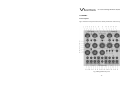
CS-8 Series Owners' Manual Omega-Phi CS-8 Series Omega-Phi Rev1.04, Oct. 2015 User manual by Carsten Schippmann Graphic design CS-8 Series: Carsten Schippmann Concept and development: Carsten Schippmann English translation by Carsten Schippmann Contact: Schippmann electronic musical instruments Dipl.-Ing. Carsten Schippmann Wartburgstr. 8 D-10823 Berlin Web: www.schippmann-music.com Email: [email protected] The manufacturer Schippmann electronic musical instruments is constantly striving for improvements and developments of their products. Therefore, we reserve the right to change technical specifications which improve our products at any time without notice. This includes the look of the unit which might differ from pictures in this manual. No part of this publication is to be reproduced, transmitted, transcribed or translated in any form or by any means whatsoever without written permission by Schippmann electronic musical instruments. 2015, Schippmann electronic musical instruments, errors excepted, subject to change without prior notice. -1- CS-8 Series Omega-Phi Rev1.04, Oct. 2015 PREFACE First of all, congratulations on the purchase of this 3U euro rack synthesizer module. This manual contains a condensed description of the functionality and addresses users with a certain level of elementary technical knowledge. ࣓ The current Thru-Zero2 െ high performance VCO Omega-Phi of the ࢾ࢚ CS-8 series is a so-called thru zero oscillator (to the power of 2 ☺). Oscillators of this type are able to reverse their curve over time from any point, if the linear FM control voltage goes thru zero into negative voltages. The oscillators' frequency will rise again by further increasing negative voltages but it has reversed its curve from anywhere at the zero point of frequency. ࢾ࣐ A typical oscillator is forced to continue its curve to the very end (maximum/minimum) before it can change its direction. It will also stop at zero or negative voltages, which cannot be processed, that it will inevitably continue its originally direction to the very end. With that "little" technical difference for Thru zero oscillators are arising extremely significant properties! For typical oscillators, namely, harmonic relationships will vary with changing modulation depths (Index). I.e., although the ratio of the carrier frequency (modulated oscillator) and the modulation frequency (modulating oscillator) could be in whole numbers, even harmonic, the modulation result will be totally disharmonic starting with that point from where the linear FM voltage goes under zero. Only for specific singular indices the result becomes harmonic, for all other indices it's chaotic. A typical harmonic percussion sound, well-known from digital FM-Synthesizers, where the index is modulated from very high to low, is absolutely impossible for typical oscillators. This ONLY works with a Thru zero oscillator! The ultimate feature of the Omega-Phi is the capability of an additional true phase-modulation section. It is connected downstream to the oscillator core and it is very similar to the sound aesthetic of the frequency modulation, when using two sine-wave oscillators even identical! Because of the downstream architecture the possibility of simultaneously processing sound synthesis arises to create PM sounds (Phi section) and having at the same time clean standard waves at the core outputs (Omega section) for other synthesis. But of -2- CS-8 Series Omega-Phi Rev1.04, Oct. 2015 course the oscillators' core can be FM'ed and the result can be processed once again with the Phi section. This creates potential! Moreover, there exists a number of synchronization possibilities, very interesting intermediate states (between "Thru zero" and "normal"), for each of the both sections (Omega & Phi) a by one octave decimated sub frequency wave and apart from PWM a funny saw-tooth wave-shaping with octave-up effect as well as at last a round suitable sine-wave. Furthermore, the frequency range can be selected very quickly and reliable by a 4-pole rotary switch and a toggle switch over seven octaves and from there another ±1 octave, as well as ±100 cents. The finally frequency range reaches from a couple of hundred seconds to umpteen kilohertz. The oscillator has, thanks of absolute high-tech-components, a very high octave linearity, finest temperature stability and because of its extremely low phase-noise (jitter) an extraordinary pure sound and powerful potential. Design and implementation meet highest technical standards concerning usability, sound quality, and electromagnetic immunity. The entire design and production work was done in Germany. Have fun! Made in Germany -3- CS-8 Series Omega-Phi Rev1.04, Oct. 2015 1. WARRANTY .........................................................................................................................5 1.1 Limited Warranty ....................................................................................................5 1.2 Terms of Warranty ..................................................................................................5 1.3 Warranty transferability ......................................................................................5 1.4 Claim for damages ..................................................................................................5 2. CE AND FCC COMPLIANCE STATEMENTS ...............................................................6 3. DISPOSAL ............................................................................................................................6 4. SAFETY INSTRUCTIONS .................................................................................................6 5. MAINTAINANCE/ CLEANING ........................................................................................7 6. GETTING STARTET............................................................................................................8 6.1 Unpacking ..................................................................................................................8 6.2 Installation .................................................................................................................8 7. CONTROLS ...........................................................................................................................9 7.1 Front panel .................................................................................................................9 7.2 Backside ................................................................................................................... 12 7.3 Initial operation .................................................................................................... 14 8.1. Layout and functions......................................................................................... 14 8.2. The e-function-generator ................................................................................ 16 8.3. The VCO core and its wave-shapes .............................................................. 17 8.4. The linear frequency modulation FM ......................................................... 19 8.4.1. The FM VCA ........................................................................................................ 22 8.5. The synchronization section .......................................................................... 23 8.6. The phase modulation PM .............................................................................. 25 8.6.1. The PM VCA........................................................................................................ 27 9. THEORETICAL PRINCIPLES ........................................................................................ 28 9.1. Frequency modulation FM .............................................................................. 28 9.2. Phase modulation PM ....................................................................................... 29 10.TECHNICAL SPECIFICATIONS AND RATINGS ................................................... 31 10.1 Specifications (generally) .............................................................................. 31 10.2 Signals and ratings ........................................................................................... 31 -4- CS-8 Series Omega-Phi Rev1.04, Oct. 2015 1. WARRANTY 1.1 Limited Warranty Schippmann electronic musical instruments warrants the mechanical and electronic components of this product for a period of two (2) years from the original date of purchase, according to the warranty regulations described below. If the product exhibits any faults within the specified warranty period that are not excluded from this warranty, Schippmann electronic musical instruments shall, at its discretion, either replace or repair the product. This warranty exists in addition to the general terms of business of the manufacturer Schippmann electronic musical instruments. 1.2 Terms of Warranty Schippmann electronic musical instruments reserves the right to execute warranty services only if the product comes with a copy of the dealer’s original invoice. Final discretion of warranty coverage lies solely with Schippmann electronic musical instruments. Any Schippmann electronic musical instruments product deemed eligible for repair or replacement under the terms of this warranty will be repaired or replaced within 30 days after receiving the product at Schippmann electronic musical instruments. Damages or defects caused by improper handling or opening of the unit by unauthorized personnel (user included) are not covered by this warranty. Products which do not meet the terms of this warranty will be repaired exclusively at the buyer´s expense and returned C.O.D. with an invoice for labour, materials, return shipping, and insurance. Products repaired under warranty will be returned with shipping prepaid by Schippmann electronic musical instruments. Outside Germany, products will be returned at the buyer´s expense. 1.3 Warranty transferability This warranty is extended to the original purchaser and cannot be transferred. No other person (retail dealer, etc) shall be entitled to give any warranty promise on behalf of Schippmann electronic musical instruments. 1.4 Claim for damages -5- CS-8 Series Omega-Phi Rev1.04, Oct. 2015 Schippmann electronic musical instruments does not accept claims for damages of any kind, especially consequential loss or damage, direct or indirect of any kind however caused. Liability is limited to the value of this product. The general terms of business drawn up by Schippmann electronic musical instruments apply at all times. 2. CE AND FCC COMPLIANCE STATEMENTS This device has been tested and deemed to comply with the DIN EN 60065 standards. This device has been tested and deemed to comply with the requirements, listed in FCC Regulations, part 15. The device complies with EN 55103-1 and EN 55103-2 standards. Because of the entirely analogue construction, this device does not generate radio frequencies and will not interfere with radio frequencies generated by other electronic devices. 3. DISPOSAL This device has been manufactured to RoHS-standards, in compliance with the requirements of the European parliament and council and is thus free of lead, mercury, and cadmium. !! Notice: This product is still special waste and is not to be disposed of through regular household waste !! For disposal, please contact your local dealer or Schippmann electronic musical instruments 4. SAFETY INSTRUCTIONS BEFORE USING THIS PRODUCT FOR THE FIRST TIME, PLEASE READ THE ENTIRE USER MANUAL THOROUGHLY. -6- CS-8 Series Omega-Phi Rev1.04, Oct. 2015 • • • • • • • • • • • • • • PLEASE AVOID SHARP BENDING OF ANY CORDS AND CABLES. CORDS SHOULD NOT BE INSTALLED WITHIN THE REACH OF CHILDREN OR PETS. DO NOT TREAD THE ENCLOSURE OF THE PRODUCT, DO NOT PLACE HEAVY OBJECTS ON IT. BEFORE REMOVING THE PRODUCT FROM THE RACK, PLEASE DISCONNECT THE POWER PLUG AND ALL OTHER CABLE CONNECTIONS. PLEASE DISCONNECT THE POWER PLUG FROM THE OUTLET IN CASE OF A THUNDERSTORM. NEVER OPEN THE ENCLOSURE OF THE PRODUCT! NEVER TRY TO MODIFY THE INTERNAL CIRCUITRY! ONLY QUALIFIED SERVICE PERSONNEL IS ALLOWED TO OPEN THE ENCLOSURE. DO NOT PLACE OPEN FIRE ON TOP OF THE PRODUCT (CANDLES, ASH TRAYS, HOT THAI CURRIES ETC). NEVER EXPOSE THE PRODUCT TO WATER, BEER, OR MOISTURE. ADULTS ARE TO MAKE SURE THAT CHILDREN FOLLOW ALL SAFETY INSTRUCTIONS. SAME THING GOES FOR PETS. AVOID MECHANICAL STRESS OR IMPACT. DO NOT DROP THE PRODUCT; EVEN IF THERE IS A CONTROL LABELLED "DROP"!. DO NOT USE THE PRODUCT WITH TOO MANY OTHER ELECTRONIC DEVICES RUNNING FROM ONE SINGLE OUTLET, ESPECIALLY IN CONNECTION WITH EXTENSION CORDS. DO NOT ATTEMPT TO SAVE MONEY ON CHEAP SOLUTIONS. BUY PROPER HIGH-DUTY POWER DISTRIBUTORS AND CORDS! NEVER USE EXTENSION CORDS WITH LESS MAXIMUM LOAD THAN THE TOTAL POWER CONSUMPTION OF ALL DEVICES CONNECTED TO A SINGLE POWER OUTLET COMBINED. OVERLOADING EXTENSION CORDS CAN CAUSE FIRE. AVOID MECHANICAL STRESS ON SOCKETS AND KNOBS / SWITCHES. PROTECT YOUR SPEAKERS AND EARS (!) AGAINST EXCESSIVE AUDIO LEVELS. THE CS-8 PHS-28 UNIT IS CAPABLE OF GENERATING EXTREMELY LOW AS WELL AS EXTREMELY HIGH FREQUENCIES. BOTH MIGHT CAUSE SERIOUS DAMAGE TO AUDIO EQUIPMENT AND EARDRUMS! 5. MAINTAINANCE/ CLEANING -7- CS-8 Series Omega-Phi Rev1.04, Oct. 2015 • • BEFORE CLEANING THE PRODUCT, PLEASE DISCONNECT THE POWER PLUG FROM THE OUTLET OR DISCONNECT THE MODULE FROM ITS POWER CONNECTOR BY PULLING THE FLAT RIBBON CABLE. USE A DRY OR SLIGHTLY MOIST CLOTH OR COMPRESSED AIR FOR CLEANING. NEVER USE ANY CLEANER OR THINNER (E.G. PAINT THINNER OR ACETON). PRINTS AND PAINTWORK WILL IMEDIATELY BE DESTROYED!! ALSO AVOID ALCOHOL (ISOPROPYLIC), GAS, SPIRITS (SCOTCH SINGLE MALTS, FOR A START) OR ABRASIVE HOUSEHOLD CLEANERS! 6. GETTING STARTET 6.1 Unpacking The box should contain the following items: - 1 x CS-8 Series VCO Omega-Phi 3HE rack-mount module - 1 x Ribbon cable (20 cm length with two 16 pole IDC-connectors) - 4 x M3 screws - 4 x polypropylene washers - This owners’ manual If the content of the box turns out to be incomplete, please get in touch with your dealer or Schippmann electronic musical instruments immediately. In case of damage caused in transit, please get back to the responsible carrier and Schippmann electronic musical instruments immediately. We will support you in this case. 6.2 Installation Place the unit on a clean, dry and sturdy surface, or use a suitable keyboard stand or 19” rack. For 19” rack mounting, a suitable rack (3U Eurorack with +/12V power supply rails) is required. The Omega-Phi uses discrete all-analogue electronics. Thus the oscillator frequency may be temperature-sensitive. We recommend placing the module away from heat sources such as radiators, lamps or other units that produce heat (e.g. power amps or internal power supplies). -8- CS-8 Series Omega-Phi Rev1.04, Oct. 2015 7. CONTROLS 7.1 Front panel Fig. 1 shows the front panel with consecutively numbered controls and jacks. Fig. 1 Omega-Phi front panel -9- CS-8 Series Omega-Phi Rev1.04, Oct. 2015 1. 2. 3. 4. 5. 6. 7. 8. 9. 10. 11. 12. 13. 14. 15. 16. 17. 18. Depth control – attenuates the modulation signal at jack "2" between 0 and 1 Modulation input (envelope symbol) jack – channels the applied signal via Depth control "1" to the control input of the FM-Index-VCA Coupling 2-pos. toggle switch – selects for the FM-modulation signal at jack "4" the coupling AC (alternating voltage) or DC (direct current) FM jack (input) – channels the applied signal to the signal input of the FM-Index-VCA FM pol 2-colour-LED – displays the current working range of the core VCO; "green" -> positive frequency range, "red" -> negative frequency range Index control – adjusts the modulation depth FM (at jack "4") at the control input of the FM-Index-VCA Scale 3-pos. toggle switch – determines the base frequency (without applied external control voltages) of the VCO Scale 4-pole rotary switch – determines the base frequency (without applied external control voltages) of the VCO Depth control – attenuates the modulation signal at jack "10" between 0 and 1 Modulation input (envelope symbol) jack – channels the applied signal via Depth control via Depth control "9" to the control input of the PMIndex-VCA Polarity 2-pos. toggle switch – selects the polarity of the PM-modulation input signal at jack "12" (non-inverted or inverted) PM jack (input) – channels the applied signal to the signal input of the PM-Index-VCA Phi limit 2-colour-LED – displays the maximum/minimum border of the possible phase-shift; "green" -> positive phase border, "red" -> negative phase border Index control – adjusts the modulation depth PM (at jack "12") at the control input of the PM-Index-VCA Tune control – detunes the frequency, set by scale, by another ± 1 octave PW control – adjusts the duty-cycle of the variable rectangle signal at jack "35" Shape control – displaces the progress of the saw-tooth curve at jack "28" related to the triangle signal (jack "30") at its corner-(reverting)points Saw 2-pos. toggle switch – selects rising or falling saw-tooth output and activates jack "31" (position "dwn/act") at the same time -10- CS-8 Series Omega-Phi Rev1.04, Oct. 2015 19. Fine control – detunes the frequency, set by scale, by another ± 100 cent 20. Depth control – attenuates the signal at the PWM input at jack "33" between 0 and 1 and varies the duty cycle of the pulse output (jack "35") 21. Depth control – attenuates the signal at the Shape input at jack "29" between 0 and 1 and varies the saw-tooth displacement 22. Phi control – adjusts the phase (Phi) of all Phi-outputs (jacks "38", "40", "42", "45") related to the Omega-outputs (jacks "28", "30", "32", "34", "35") between ±360° 23. Value control – determines the setting-voltage of the triangle, when a Sync trigger at jack "27" occurs (±5 V) 24. Bias 2-pos. toggle switch – switches on an internal bias voltage at the linear-FM-input to generate a basic frequency ("norm") or of ("Zero") (oscillator doesn't oscillate anymore without voltage at the FM-input) 25. Zero 2-pos. toggle switch – turns on the Thru Zero capability (phase reverse) ("On") or off ("Off") 26. Rectifier 2-pos. toggle switch – determines the method of rectifying at the FM-linear input, full-wave ("Full") or half-wave for only positive input voltages ("Half (pos)") - this is a special function due to the applied thru zero architecture 27. Set jack (input) – Synchronization input sets the triangles output value to the voltage value (adjusted with Value control "23") with a positive going trigger (0 V -> +5 V) (hard sync) 28. Saw (Symbol) jack (output) – saw-tooth (with shaping) of the VCO core (Omega), 5 - 10 Vpp 29. Shape jack (input) – CV-input, attenuated by control "17", displays the saw-tooth curve 30. Triangle (Symbol) jack (output) – Triangle output of the VCO core (Omega), 10 Vpp 31. Ramp jack (digital-input) – only active in position "dwn/act" of the switch "18", 0 V = saw-tooth rising, +5V (or floating input) = saw-tooth falling 32. Sinus (Symbol) jack (output) – Sine-wave output of the VCO core (Omega), 10 Vpp 33. PWM jack (input) – CV-input, attenuated by control "20", varies the dutycycle at jack "35" 34. Sub Rectangle (Symbol) jack (output) – 50%-rectangle output decremented by one octave, 10 Vpp 35. Pulse (Symbol) jack (output) – rectangle output with variable duty-cycle of the VCO core (Omega), 10 Vpp -11- CS-8 Series Omega-Phi Rev1.04, Oct. 2015 36. 1V/Oct. jack (input) – CV-input for calibrated exponential control of the oscillator frequency (Omega & Phi) with a sensitivity of one octave per Volt 37. 0.5V/Oct. (non-cal.) jack (input) – CV-input for non-calibrated exponential control of the oscillator frequency (Omega & Phi) with a sensitivity of two octaves per Volt 38. Saw (Symbol) jack (output) – saw-tooth (with Shaping) of the Phase section (Phi), 5 - 10 Vpp 39. Zero Crs jack (output) – Output of the Zero-Cross-Detector of the FMlinear input, 5 Vpp - this is a special function due to the applied thru zero architecture 40. Triangle (Symbol) jack (output) – Triangle output of the phase section (Phi), 10 Vpp 41. Up jack (input) – Synchronization input sets the triangles direction to rise up with a positive going trigger (0 V -> +5 V) (soft sync) 42. Sinus (Symbol) jack (output) – Sine-wave output of the phase section (Phi), 10 Vpp 43. Down jack (input) – Synchronization input sets the triangles direction to fall down with a positive going trigger (0 V -> +5 V) (soft sync) 44. Sub Rectangle (Symbol) jack (output) – 50%-rectangle output (Phi section) decremented by one octave, 10 Vpp 45. Reverse jack (input) – Synchronization input sets the triangles direction to its current opposite direction (reverse) with a positive going trigger (0 V -> +5 V) (soft sync) 7.2 Backside Fig. 2 shows the back of the module with consecutively numbered elements. -12- CS-8 Series Omega-Phi Rev1.04, Oct. 2015 Fig. 2 back side of the module 1. 2. 3. 4. 5. 6. THD off1 12-gauge-Trimmer P9 – THD-calibration of Sinus' (OmegaOutput) THD g1 12-gauge-Trimmer P8 – THD- calibration of Sinus' (OmegaOutput) IC 1 - pinned VCO module THD g2 12-gauge-Trimmer P10 – THD- calibration of Sinus' (Phi-Output) THD off2 12-gauge-Trimmer P9 – THD- calibration of Sinus' (Phi-Output) Range 0 25-gauge-Trimmer P2 – calibration of the lowest basic frequency (55 Hz) -13- CS-8 Series Omega-Phi Rev1.04, Oct. 2015 7. 8. 9. 10. 11. 12. 13. 14. Range MID 25-gauge-Trimmer P5 – calibration of the standard A (440 Hz) Range high 25-gauge-Trimmer P4 – calibration of the upper frequency (7040 Hz, upper row) ZERO 25-gauge-Trimmer P12 – calibration to 0 Hz at Bias = Zero & exp. frequency = 50 kHz korr high 25-gauge-Trimmer P1 – calibration of gain error of the egenerator at 20 kHz PVCA off 12-gauge-Trimmer P6 – Offset-calibration of the phase modulation-VCA's 1 V/ OCT 25-gauge-Trimmer P3 – calibration of the scale at jack "36" to 1 Volt/octave FVCA off 12-gauge-Trimmer P7 – Offset-calibration of the frequency modulation-VCA 16 Pin power supply-box header 7.3 Initial operation The power connector’s (8) pin-out in top view (refer to fig. 2) is assigned as follows: Bottom to top, left to right. Thus pin 1 is located at bottom left, pin 2 above pin 1 etc. Pin 15 is at bottom right, pin 16 at top right. Pin 1, 2 = -12 V (labeled with a triangle) Pin 3-8 = GND (regarding ground, 0 V), located outward on all jacks Pin 9, 10 = +12 V Pin 11-16 = not connected To hook up power to the module, connect one of the IDC-connector of the included flat ribbon cable to the box header (refer to fig. 2). Observe guide key for the polarity of the connector in order to avoid pin reversal. The red tag of the cable is to match the triangle-label. 8. MODULE DESCRIPTION 8.1. Layout and functions -14- FM -15- Depth Σ VCA -5 V +5 V Index off AC Coupling Bias +5 V SUM Full Half ULIN Fig. 3a Structure of the VCO core 1 V/Oct. SUM Fine Shape Tune On VCO core & Waveshaping PW Off Zero -5 V Value ULIN exp(Usum) 0.5 V/Oct. LFO lower upper FM pol Exp-Generator green/red 440/7040 220/3520 110/1760 55/880 Scale Rectifier Zero cross Detector +5 V Depth Depth up Saw dwn/act Shape PWM Triangle Sine Pulse Omega 50% sub Rectangle Sawtooth Ramp Zero Crs Up Down Sync Reverse Set CS-8 Series Omega-Phi Rev1.04, Oct. 2015 CS-8 Series Omega-Phi Rev1.04, Oct. 2015 green/red Phi limit PM 180° Polarity VCA +5 V Depth SUM Phase-Shifter 0° -1 Σ +5 V Index -5 V Triangle Sine Sawtooth Phi 50% sub Rectangle Phi -5 V VCO core Omega Fig. 3b Structure of the phase-shifting section Fig. 3a and 3b showing the complete structure of the oscillator. Now, step by step all parts of it will be described in the following chapters. 8.2. The e-function-generator An e-function-generator (Exp-Generator, Fig. 3a) is mostly part of every music VCO. They have a linear input and the exponential input. The linear one is scaled Hertz/Volt and the exponential one in octaves/Volt or decades/Volt. Generally, for resulting voltage output UC one obtain the mathematical expression: ࢁ ൌ ࢁ ∙ ࢙࢛ , where α is an exponential scaling-factor and Usum the total input voltage at the exponential input (following called e-input) and it is the result of the following parts. First of all there are the Scaleswitches. ∙ Scale-switches: The 3-position toggle switch (upper, lower, LFO) determines the range of the 4-position-rotary switch. In position "lower" the lower row of frequencies of the rotary switch will be output by the VCO core (no further control voltages applied) in steps of octaves 55 Hz, 110 Hz, 220 Hz and 440 Hz. In position "upper" it is the upper row also in octave steps 880 Hz, 1760 Hz, 3520 Hz and 7040 Hz. In position "LFO" the oscillators frequency at "55 Hz"position of the rotary switch and at full CCW (counter clockwise) of the Tunecontroller is about 0.08 Hz. -16- CS-8 Series Omega-Phi Rev1.04, Oct. 2015 Tune: The normal position of this controller is the middle. In the positions "upper" and "lower" it decrements/increments (left/right) the oscillators' frequency by 1 octave (a bit more). In position "LFO" it has a much wider range. In position "55 Hz" the frequency ranges (from left to right) from about 0.08 Hz to 12 Hz, that's a factor of 150 and equals 7.2 octaves. The rotary switch still octaves the frequencies. So, in position "440 Hz" Tune ranges from 0.64 Hz to about 100Hz. Fine, so far. Fine: This controller was intended for finest frequency corrections and definite beats. Normal position is the middle and it detunes the frequency once again by 100 cent (a bit more). 100 cent equals a semitone step at the equallytemperate scale. 1 V/Oct-jack: An external voltage at that jack increments (or decrements) the current oscillator frequency with a sensitivity of one octave (x2) per +Volt, resp. ( 2) per -Volt (negative voltages). This input is calibrated. 0.5 V/Oct-jack: An external voltage at that jack increments (or decrements) the current oscillator frequency with a sensitivity of two octaves (x4) per +Volt, resp. (4) per -Volt (negative voltages). This input is not calibrated, i.e. this scale is tolerant with some percent and different from VCO to VCO. Each of these influence quantities at the e-input operates by a frequency multiplication not by summing! 8.3. The VCO core and its wave-shapes The VCO output its frequency as different waveforms, which are sinus, triangle, saw-tooth, variable rectangle and a 50% rectangle with half frequency (one octave down). Fig. 4 shows these functions and there phase relations e.g. as voltage versus time. -17- CS-8 Series Omega-Phi Rev1.04, Oct. 2015 Sinus Triangle (reference) Saw - shape left Saw - shape left side Saw - shape mid Saw - shape right side Saw - shape right PW mid PW right Pulse PW left SUB 50% Rectangle Fig. 4 The waveforms of the VCO core (Omega-outputs) The triangle is the reference for all other waveforms. PW/PWM/Depth: The controller PW determines as shown in the graph the duty-cycle from 0% (full CCW) to 100% (full clockwise, CW) of the pulse wave. -18- CS-8 Series Omega-Phi Rev1.04, Oct. 2015 For Depth at full CW a voltage range of 2 V at the PWM input jack controls the total range of this parameter. Shape/Shape/Depth: The Shape-controller breaks the saw-tooth wave during passing through at a further point. The graphs illustrate how. In the middle position one obtain a saw-tooth with double frequency and half amplitude (5 Vpeak-to-peak instead of 10 Vpp). Both in full CCW and full CW position one obtain a full saw-tooth wave displaced by a half triangle wave (180°) (that's not the same as inverting!). The Depth-controller in full CW voltage range of 5 V at the Shape jack controls totally this parameter. Ramp-jack/Saw-switch: The Saw-switch selects for the saw-tooth output the direction either rising (position "up") or falling (position "dwn/act") for both Omega section and Phi section. In position "dwn/act" the jack Ramp is activated. A voltage of +5 V or floating input means "falling" and 0V "rising". Because this function equals a multiplication with 1, one obtain a semianalogue/semi-digital ring modulator! 8.4. The linear frequency modulation FM In Abb. 3a above the ULin-input of the e-generator, which finally is fed with the FM voltages, goes to the output of a Rectifier. (There may exist different solutions for the realization of a thru zero oscillator, but the realized approach here seemed to be the most elegant one.) To imagine generally how FM works and how a carrier waveform becomes influenced by modulation, some explanations based on graphs will follow. Fig. 5a shows (top) the non-modulated sine wave (carrier) of the oscillator, the next graph below shows the rectifier output (modulator); this curve modulates now the carrier at the ULin-input of the e-generator. It was chosen a cosine-curve with same frequency as the carrier to obtain more intuitive wave shapes, because the FM-result depends strongly on the phase relationships of carrier and modulator. The modulation amplitude was chosen, that the minimum at the rectifier output exactly becomes zero. The modulation index is =1. I.e., Would one omit the cosine modulator, the rectifier output would be 1 in graph. This is the normalized so-called bias (pre-voltage). With the switch Bias: it could be switched on (position "Norm") or off (position "Zero"). If it is switched off the oscillator will stop oscillate without any voltage at the FM -19- CS-8 Series Omega-Phi Rev1.04, Oct. 2015 input, regardless of the scale setting and any other control voltages at the einput. So, the position "Norm" is very important for the normal mode. The lower graph shows the modulation result. At that points, where the rectifier output is zero (dotted line), the oscillator stops for this moment, because the oscillators' frequency IS zero. Exactly up to here every typical oscillator with linear FM-input can process this, too. Sinus (Carrier) 2 Rectifier (Index=1) 1 0 1 FM result -1 Fig. 5a FM with Index=1 Fig. 5b shows under the same preconditions as above for carrier and modulator the results for index =2. I.e., die modulation amplitude is twice as high as the bias. For the wave of the modulator the rectifiers' output would reach the values+3 (normalized graph) and -1. Because the oscillator doesn't "understand" negative voltages at its ULin-input, the full-wave-rectifier reconstruct the values +3 und +1 (upper graph). to bring the oscillator to working correct, the oscillator core receives an information from a so-called zero-cross-detector (s. Fig. 3a) of a thru zero event at the rectifiers' input. Whenever the detector sends the information about a (theoretical) conversion at the ULin-input, the oscillator will reverse its current curve direction, immediately. This is btw also true for saw-tooth waves; they fall or rise depending on the detectors' sign. -20- CS-8 Series Omega-Phi Rev1.04, Oct. 2015 3 (Full-wave)-Rectifier (Index=2) 2 1 0 1 FM result (Thru zero) -1 1 FM result (not Thru zero) -1 Fig. 5b FM with Index=2 The middle graph shows the true FM result (thru zero technique), whereas the lower indeed gets the rectifiers output but no more the detector information. It is evident that the result is no longer periodic and hence not harmonic. However, at the zero points of the rectifier the slopes in both results is zero for this moment (dotted lines). Only in thru zero mode the oscillator reverse its direction before reaching its minimum/maximum, whereas in zero-off-mode it continues its direction up to its very end. For switching "on" or "off" the thru zero mode there is the Zero-switch: Thru zero mode in position "on" and off in position "off". I.e., The information of the zero-cross-detector for the oscillators' core is active or not. The information about the rectifiers' input sign will be displayed by the FM pol LED: Green for positive voltages at the rectifier input (this is still possible with negative FM-inputs, if the bias is active!) and red for negative values. Zero Crs-jack: Moreover the output of the zero-cross-detector is applied at this jack. 0 V for negative, +5 V for positive. This signal is suitable for exotic synchronizations! Fig. 5c shows the case for half-wave rectifying mode. -21- CS-8 Series Omega-Phi Rev1.04, Oct. 2015 3 (Half-wave)-Rectifier 2 (Index=2) 1 1 FM result (not Thru zero) -1 Fig. 5c FM with Index=2 and half-wave rectifying This is the mode of every typical oscillator. When the input voltage at the ULininput becomes zero or lower, nothing more will happen; the oscillator stops. And it's also evident that the result is not periodic. Rect-switch: This switch determines the mode of the rectifier. In position "Full" it works as shown in Fig. 5b and in position "Half" as in Fig. 5c. 8.4.1. The FM VCA Fig. 3a above shows, that the rectifier is fed with the bias and a further external modulation input signal. This modulation signal will be applied at the FM-jack: It channels the input unabated to an VCA-input. These input voltages shouldn't exceed 10 V, if linear working of the VCA is wished, best is 5 V. Index/Depth-controller: The Depth-controller attenuates the modulation signal at jack 2 (Envelope symbol) between 0 and 1. This signal will be added to the value of the Index-controller. In case that nothing is applied at Depth or it's in full CCW position in the first instance Index, turning from the middle position (no effect) to full CW, the modulation depth will increase. Turning it to the left up to full CCW, nothing more will happen. At Depth positive as negative voltages could be applied, which either increases or decreases the index value. By turning the Index-controller to the left high (positive) modulation voltages at the Depth-controller can be cut. Coupling-switch: This switch selects the kind of coupling the VCA-FM-input to the rectifier. In position "AC" (capacitive decoupled) only alternating voltages with frequencies higher than 8 Hz will be processed. This kind of coupling -22- CS-8 Series Omega-Phi Rev1.04, Oct. 2015 could become very important to avoid a detune of the oscillator by lowest offset voltages of internal electronic or direct current voltages as part of the modulation signal. In position "DC" direct current voltages can be processed. 8.5. The synchronization section The principle of operation of the different synchronizations shall be shown exemplarily for triangle and saw-tooth waves. Any of the overall 4 Sync input jacks need a minimum positive voltage of +3 Volt to trigger its function. These inputs are equipped with an upper and a lower threshold, so, they are able to process any wave shapes, which could slowly approach the triggering threshold (+3 V). After triggering by exceeding the upper threshold the signal has to fall below the lower threshold (+1 V) before another trigger can occur (hysteresis). To make it easier in the following graphs the syncs appears as unit step functions. The designations "Up", "Down" and "Reverse" are related to the curve direction of the triangle wave. The saw-tooth is derived from the triangle and so it could lead to very different shapes; with these Sync-functions it's not possible to reverse the saw-tooth's direction! This is only possible for negative voltages at the FM input in thru zero mode or with the Ramp/Saw-function (s. above). Sync Up/Down-jacks: Fig. 6a illustrates, that "Up" and "Down" triggers will only change the curve direction, if the trigger occurs at a time when the triangle has currently the inverse direction, otherwise nothing special will happen. -23- CS-8 Series Omega-Phi Rev1.04, Oct. 2015 Sync up Sync down Triangle Sawtooth Fig. 6a Synchronization Up and Down Sync Reverse/Set-jacks: "Reverse" means that with every trigger the current curve direction will be reversed. The "Set"-function is commonly known as hard-sync. A trigger at the Set-jack set the triangle immediately to that value adjusted with the Value-controller: It can be set to all positive or negative values (±5 V) the triangle can attain. The current direction will be not influenced, however. The triangle will continue its direction, even when set back just before reaching an extremum. But, combining of "Set" and e.g. "Up" is useful to force the triangle to definite values an slopes, this is the classical hard-sync. Fig. 6b illustrates the Set function for 0 V of the Value-controller in combination with "Reverse". -24- CS-8 Series Omega-Phi Rev1.04, Oct. 2015 Sync Reverse Sync Set Triangle Sawtooth Fig. 6b Synchronization Reverse and Set 8.6. The phase modulation PM The phase-shifter shown in Fig. 3b above is connected downstream to the oscillator core. Everything what will be processed here will have NO reaction to the oscillator core. The sound aesthetic and the spectrums are very similar to FM. However, there are existing clear differences. First of all the similarities and even identities. Considering solely sine-wave functions and a system of two oscillators (carrier and modulator) then theoretically there is nothing which could be done with FM which cannot also be done with PM. So, that what is shown in Fig. 5a above is also possible with PM as shown in Fig. 7a. To obtain the same wave shape, only the phasing between carrier and modulator has to be chosen differently. The modulator now is sine, not cosine. The results for the indices 1 and 6 are shown. -25- CS-8 Series Omega-Phi Rev1.04, Oct. 2015 Sinus (VCO-Kern) Sinus (Modulator) PM result (Index=1) PM result (Index=6) Fig. 7a PM with Index 1 and 6 A limit of the Phase-shifter is its phase shifting range. The output functions at the Phi-output jacks: ,namely saw-tooth, triangle, sine, and 50% rectangle with half frequency can be shifted referred to the VCO core (Omega-outputs) by maximum 360° (±2π, radian measure) with the Phi-controller: The phasing of the waves by itself has no effect of their sound and spectrum. Only changes of the phase causes real frequency shifts at the Phase-shifters' output. This fact is one of the big differences to the FM. And this, finally, means that the modulation index goes proportional to the modulation frequency without any physically limit! So, the index is not a constant as for the FM. Fig. 7b shows the PM result for the as twice higher modulation frequency without doubling the index as it would be necessary for the FM to get the same result. -26- CS-8 Series Omega-Phi Rev1.04, Oct. 2015 Sinus (VCO-Kern) Sinus (Modulator) PM result (Index=2) PM result (Index=12) Fig. 7b PM with doubled index by frequency doubling (modulator) One can say, that the phase modulation is a "harder" modulation than FM, since one cannot generate stepping waves due to modulation; an infinite short and infinite high voltage pulse would be needed to generate a definite jump in a sine carrier. With the PM it becomes easy. Take a step function as the modulator and the phase jumps. Because it is the phase change which could be heard, with low-frequency sawtooth waves, e.g., which amplitude is adjusted to shift the phase by exactly 360° or 720°, constant detunes can be generated. E.g. with a rising saw-tooth of 1 Hz, which shifts the phase repetitive by 360°, detunes the output frequency by 1 Hz, with 720° phase shift by 2 Hz. Superposition with VCO core output (Omega) one obtain a fat beat as you would have two detuned oscillators. 8.6.1. The PM VCA Fig. 3b above shows that the control input of the Phase-shifter is fed by a value of the Phi-controller on the one hand and by an output of a VCA on the other hand. the modulation signal will be applied at the -27- CS-8 Series Omega-Phi Rev1.04, Oct. 2015 PM-jack: It channels the input unabated to an VCA-input. These input voltages shouldn't exceed 10 V, if linear working of the VCA is wished, best is 5 V. Index/Depth- controller: The Depth-controller attenuates the modulation signal at jack 9 (Envelope symbol) between 0 and 1. This signal will be added to the value of the Index-controller. In case that nothing is applied at Depth or it's in full CCW position in the first instance Index, turning from the middle position (no effect) to full CW, the modulation depth will increase. Turning it to the left up to full CCW, nothing more will happen. At Depth positive as negative voltages could be applied, which either increases or decreases the index value. By turning the Index-controller to the left high (positive) modulation voltages at the Depth-controller can be cut. A capacitive decoupling is not necessary, because offsets only leading to a constant phasing, what could be corrected with the Phi-controller. But, as mentioned above, the polarity could be of interest and therefore there is the Polarity-switch: This switch inverts or not the modulation signal at the PMinput, inverting in position "180°", non-inverting in position "0°". 9. THEORETICAL PRINCIPLES To understand the mathematics behind these modulating operations, specific knowledge are absolute requirements. So, this short chapter turns to complete experts, but shouldn't be unmentioned for the sake of completeness. 9.1. Frequency modulation FM In general terms the frequency modulation with a sinus function as a carrier could be written as follow ൌ ࢚ ∙ ࣓ ࣓ ∙ ∙ FM(t) is the modulation result, A0 its amplitude, ω0 is the basic angular frequency of the oscillator (that is 2πf0, with f0 the oscillator frequency) given -28- CS-8 Series Omega-Phi Rev1.04, Oct. 2015 by the bias (s. above). mFM can be seen as the modulation index or simply index. M(t) is the modulation signal normalized to ±1. The term in the round bracket describes the phase (this means the state of the carrier) of the sinecarrier as a function of time. The term in the squared bracket is in total the time depending momentary frequency at any time of the carrier. So, to come to the phase of the carrier the frequency term has to be integrated over the time. Frequency, generally means now, by how much degrees per second the phase is running forward, stopping or reverting - the result is no longer sinusoidal! Taking for M(t)=sin(ωmt+ϕF) a sinus-function, as chosen in all the examples above, with ωm as the modulation angular frequency and ϕF as an arbitrary constant phase value, then is ൌ ࢚ ∙ ࣓ ࣓ ∙ ∙ ࣓ and the integral calculated leads to ൌ ∙ ࣓ െ ࣓࣓ ∙ ∙ !" ࣓ െ !"# The term in the overall round bracket, now, is the time depending phase of the carrier, resp. FM(t). 9.2. Phase modulation PM The phase modulation can be written as: $ ൌ ∙ ࣓ ∙ Φ∙ Because M(t) influences only and directly the carriers' phase and not the frequency, there is no integral. Φ = 2π is the half value of the above mentioned phase shifting range of the Phase-shifter. With M(t)=sin(ωmt+ϕP) again as a sinus-function leads to $ ൌ ∙ ࣓ % ∙ Φ ∙ ࣓ & Formal PM(t) and FM(t) are interchangeable with -29- CS-8 Series Omega-Phi Rev1.04, Oct. 2015 ' ∙ Φ ൌ ' ∙ బ and ϕF, ϕP, ϕC can be chosen that PM(t) and FM(t) becomes equal. Well! We computed, respectively written the wave-functions for FM(t) and PM(t), with sinus-functions for carrier and modulator. But the phase modulation generates also frequency shifts as the FM. For FM the frequency was the starting point (we computed the current phase as a function of time by integration of the frequency as function of time). To obtain the momentary frequency ωPM(t) for the PM, the term in the round bracket behind the sinus of PM(t), namely the phase as a function of time φ ൌ ࣓ ∙ Φ∙ is to derivate with respect to time (inversion of integration): ࣓ ൌ ∅ ൌ ࣓ ∙ Φ∙ And with M(t)=sin(ωmt+ϕP) we finally obtain ࣓ ൌ ࣓ ∙ Φ ∙ ࣓ ∙ !"࣓ ) and for FM(t) with M(t)=sin(ωmt+ϕF) it is already written above ࣓ ൌ ࣓ ࣓ ∙ ∙ ࣓ Because the extremes of sinus and cosine are ±1, for the maximum/minimum momentary frequencies we obtain: ࣓ / ൌ ࣓ , ∙ Φ ∙ ࣓ ࣓ / ൌ ࣓ ࣓ , ∙ As one can see for the PM ωm is a constant of proportionality in ωPM(t); that means that the index (modulation depth) increases with the modulation frequency ωm, whereas the index for FM is constant, the modulation frequency ωm doesn't appear, only the constant index mFM and the constant ω0. -30- CS-8 Series Omega-Phi Rev1.04, Oct. 2015 All this doesn't say anything about the spectrums of that modulation results. This can generally not be solved without numerical algorithms done by the computer. Many further investigation could be done, but therefore I have to refer to the literature. 10.TECHNICAL SPECIFICATIONS AND RATINGS 10.1 Specifications (generally) Input- and output-sockets: mono jack sockets 3.5 mm (1/8”) Input sockets have grounded switch (0 V) Power: -12 V / +12 V (polarity protection) Power consumption: max. 150 mA (for both supplies ±12 V) Proper ambient temperature: 0 °C – +55 °C / 32F – 131F Net weight (module only): approx. 200 g / 0,44 lbs Dimensions (W x H x D): 24 PU (121.6 mm) x 3 HU (128.5 mm) x 47 mm Installation depth (behind the panel) <30 mm 10.2 Signals and ratings Max. input voltage at all input jacks (): ±15 V -31-