1
EN
Operating Manual
Digital gauge DL01
1. General Information
2. Product identification
1.1 Information concerning the user manual
Follow the safety and handling instructions that are
set out in this user manual. Compliance with the
applicable accident prevention regulations and safety
regulations as well as with national installation standards and recognized codes of practice must also be
ensured.
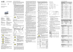
The type plate serves to identify the device. The most
important data can be taken from this. The order
code is used for unique identification of your product.
This user manual is part of the device and should be
kept accessible to personnel at all times in the immediate vicinity of the installation location of the device.
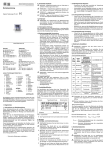
manufacturing label for display
3.2 General installation instructions
- Carefully remove the device from its packaging
and dispose of the packaging properly.
- Then proceed as described in the following installation instructions.
Ordering code Serialnumber
Type designation Supply
manufacturing label
for pressure sensor module
1.2 Symbols used
Headquarters
BD SENSORS GmbH
BD-Sensors-Str. 1
D - 95199 Thierstein
Germany
Tel.: +49 (0) 9235-9811-0
Fax: +49 (0) 9235-9811-11
Eastern Europe
BD SENSORS s.r.o.
Hradištská 817
CZ - 687 08 Buchlovice
Czech Republic
Tel.: +42 (0) 572-4110 11
Fax: +42 (0) 572-4114 97
Russia
BD SENSORS RUS
39a, Varshavskoe shosse
RU - Moscow 117105
China
BD SENSORS China Co, Ltd.
Room B, 2nd Floor, Building 10
No. 1188 Lianhang Rd.
201112 Shanghai,
China
Tel.: +86 (0) 21-51600 190
Fax: +86 (0) 21-33600 613
-
Russia
Tel.: +7 (0) 95-380 1683
Fax: +7 (0) 95-380 1681
You can find our offices in
EUROPA
Belgien
Dänemark
England
Finnland
Frankreich
Griechenland
Italien
Litauen
Luxemburg
Niederlande
Norwegen
Polen
Portugal
Rumänien
Schweden
Schweiz
Slowakei
Spanien
Türkei
Ukraine
AFRIKA
Ägypten
Südafrika
ASIEN
Indien
Iran
Israel
Japan
Kasachstan
Korea
Malaysia
Singapur
Taiwan
Thailand
Vietnam
AUSTRALIEN
The addresses of our overseas offices can be found
at www.bdsensors.de. Data sheets, user manuals,
ordering codes and certificates are also available for
you to download from our website.
Table of contents
1. General Information
2. Productidentification
3. Installation
4. Connection display with pressure transmitter
module
5. Supply / Changing the batteries
6. Datalogger
7. Initial start-up
8. Placing out of service
9. Operation
10. Maintenance
11. Service / Repair
12. Disposal
13. Guarantee Conditions
14. Declaration of Conformity / CE
-
- Nature and source of danger
- Measures to prevent danger
Warning term
Fig. 1 Type plate
Warning term
Meaning
3. Installation
DANGER
Immediate danger!
Failure to observe will result
in death or serious injury.
3.1 Installation and safety instructions
WARNING
Possible danger!
Failure to observe may result
in death or serious injury.
CAUTION
Dangerous situation!
Failure to observe may result in
slight or moderate injury.
NOTE – Tips and information for the user in
order to ensure trouble-free operation.
Input
DANGER
WARNING
Installation, commissioning, operation, maintenance,
decommissioning and disposal may be carried out
only by appropriately qualified specialist personnel.
1.4 Limitation of liability and warranty
Failure to follow the instructions or observe technical
regulations, improper use or use of the device in a
manner other than that intended, or alteration or
damage to the device will void the warranty and
invalidate claims for liability.
1.5 Intended use
- The battery powered digital gauge has been designed for extremely high demands in the sector of
leak testing and pipeline monitoring. It can be
easily and quickly installed in situ.
- It is in the responsibility of the user to verify
whether the chosen device is suitable for the
intended application. In case of any doubts, contact
our sales department to eliminate any
indistinctness. BD SENSORS does not assume
any liability for an incorrect selection and its
consequences!
- Permissible media are gases or liquids, which are
compatible with the media wetted parts described
in the data sheet. In addition it has to be ensured,
that this medium is compatible with the media wetted parts.
- The technical data listed in the current data sheet
are engaging. If the data sheet is not available,
please order or download it from our homepage.
(http://www.bdsensors.com)
WARNING
Danger of death through
incorrect use
- In order to avoid accidents, use
the device only in accordance
with its intended use.
1.6 Package contents
Please verify that all listed parts are undamaged
included in the delivery and check for consistency
specified in your order.
The batteries are already used. The circuit is interrupted by an insulation foil. Take this before first
introduction, see in addition battery change!
Ordering code
The manufacturing label must not be removed
from the device!
1.3 Qualification of personnel
Work on electrical components must be performed
only by a qualified electrician and in accordance with
the applicable regulations and guidelines.
lock against
protection
3.3 Installation instructions for DIN 3852 connectors
– Subject to technical alteration –
www.bdsensors.com
4. Connection display with pressure transmitter module
Caution
-
Danger of death from electric
shock
- Install the device only when the
machine is depressurized and the
power supply has been switched
off!
Danger of death from improper
installation
- Installation must be performed
only by appropriately qualified
specialist personnel who have
read and understood the user
manual.
Destruction of the device with
not material-appropriate use.
- Do not use the display to
tightenor solve to the mechanical
connection of the pressure
transmitter module!
Handle this electronic precision measuring device carefully in packed as well as in unpacked
condition!
The device must not be subject to any changes
or modifications.
The device may not be thrown!
To avoid damaging the diaphragm, remove
packaging and protective cap only directly before
starting up the device. A delivered protective cap
must be stored!
Place the protective cap on the pressure port
again immediately after disassembling.
Handle the unprotected diaphragm very carefully
- it is very sensitive and may be easily damaged.
Do not use any force when installing the device
to prevent damage of the device and the plant!
Take note that no inadmissibly high mechanical
stresses occur at the pressure port as a result of
the installation, since this may cause a shifting of
the characteristic curve or to the demage. This is
especially important for very small pressure
ranges as well as for devices with a pressure
port made of plastic.
In hydraulic systems, position the device in such
a way that the pressure port points upward (venting).
Provide a cooling line when using the device in
steam lines.
-
DO NOT USE ANY ADDITIONAL SEALING
MATERIALS, SUCH AS YARN, HEMP OR
TEFLON TAPE!
Check to ensure the proper groove fitting of the
o-ring and additionally to ensure no damage to
the o-ring.
Ensure that the sealing surface of the taking part
is perfectly smooth and clean. (RZ 3.2)
Screw the device into the corresponding thread
by hand.
If you have a device with a knurled ring, the
transmitter has to be screwed in by hand only.
Devices with a spanner flat have to be fully tightened with an open-end Devices (G1/4": approx.
5 Nm; G1/2": approx. 10 Nm).
The indicated tightening torques must not be
exceeded!
3.4 Installation instructions for EN 837 connectors
- Use a suitable seal that is compatible with the
process medium and the pressure to be measured (e.g. a copper seal).
- Make sure that the sealing surface of the receiving part is perfectly clean and smooth.
(RZ 6,3)
- Screw the device into the mounting thread by
hand.
- Then tighten it with the open-end wrench (for
G1/4": approx. 20 Nm; for G1/2": approx. 50
Nm).
- The specified tightening torques must not be
exceeded!
3.5 Installation instructions for NPT connectors
- Additional seal materials, e.g. PTFE tape, may
be used to provide sealing.
- Screw the device into the mounting thread by
hand.
- Then tighten it with the open-end wrench (for
1/4" NPT: approx. 30 Nm; for 1/2" NPT: approx.
70 Nm).
- The specified tightening torques must not be
exceeded!
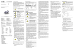
pressure transmitter module
display
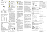
Fig. 2 Lock against protection
Connect display with pressure transmitter module
as follows:
- bring together carefully the display with pressure
transmitter module.
- press the display sturdy pressure transmitter module to this engages.
5. Supply / changing the batteries
As soon as in the display the announcement of
"battery" is shown, carry out battery change as
follows:
- unscrew three fixing screws with a suitable
screwdriver.
- take the battery case cap and exchange the
batteries 3 x 1.5 V AA (remove the insulation
foil before first introduction).
- lock the device after that properly
An incorrect usage may cause a leak out of
batteries and so a damage the device!
Never combine batteries of different types or old
with new ones!
Make sure that the batteries are connected
correctly with the corresponding contacts in the
battery tray.
Never try to charge batteries, demount them, or
short-circuit them.
Keep the batteries away from heat and
unshielded flame.
fixing screw
battery case
battery
protection screwing
connecting cable
battery case cap
comm. interface
insulation foil
Fig. 3 Battery case cap and communication interface
6. Data logger
The battery powered digital gauge disposes of an
integrated data logger. The measuring values stored
away in the device can be selected above the communication interface by means of software BD|LOG
(included in delivery).
6.1 PC - connection
Connect device with a computer as follows:
- unscrew the protective screwing of the communication interface with a suitable slit screwdriver.
- connect the handle plug of the connecting cable
(included in delivery) with the interface socket of
the device. Connect the side with the USB plug
with a free USB connection on the computer.
- install the COM driver and data logger software
BD|LOG, receive available on CD (included in
delivery).
- after the use, disconnect the connection and
lock the protection screwing again properly.
7. Initial start-up
remove the insulation foil before first introduction.
Before start-up, the user has to check for proper
installation and for any visible defects.
The device can be started and operated by
authorized personnel only, who have read and
understood the operating manual!!
The device has to be used within the technical
specifications, only (compare the data in the data
sheet)!
8. Placing out of service
When dismantling the device, it must always be
done in the depressurized and currentless
condition! Check also if the medium has to be
drained off before dismantling!
Depending on the medium, it may cause danger
for the user. Comply therefore with adequate
precautions for purification.
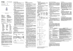
9.3 Menu list
9. Operation
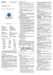
9.1 Operating and display elements
barograph
timer / battery
time
display
Switch on
Menu 1/9
on / off
Menu 2/9
date / time / info
Menu 3/9
Units
pressure value
right button
left button
menu - button
temperature
Menu 4/9
Min / Max Values
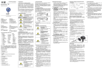
Fig. 4 Display and operating foil
The display of the measuring value as well as configuring the single parameters occurs menu-steered
about a LC display capable of graphic arts. The
single functions are regulated on the basis of threefront-sided arranged push buttons.
The menu system is closed, thereby one can
"browse" forward as well as backward by the single
setting menus to reach to the desired setting point.
10. Maintenance
The device can be switched on with every button (left button, menu button, right button).
By push the menu button the operating mode will be selected / left / ("Menu" / "Exit").
Setting of topical time and the topical date. Software version will be showed.
Setting of the pressure unit
adjustable units: [bar], [mbar], [PSI], [inHg], [cmHg], [mmHg], [hPa], [kPa], [MPa], [mmH2O], [mH2O], [kg/cm 2] or
[user] (the user-defined unit can be programmed only by means of the software BD|LOG), a conversation of all
pressure related parameters is carried out automatically
Setting of decimal places
adjustable decimal place: standard [Std], [+1], [+2]
Setting of the temperature unit
the unity is not adjustable. Factory setting [°C]
Displaying of Min / Max Values
Pmin - Minimum pressure display: The minimum pressure applied during measuring is shown in the display.
Pmax - Maximum pressure display: The maximum pressure applied during measuring is shown in the display.
Tmin - Maximum pressure display: The minimum temperature during measuring is shown in the display.
Tmax - Maximum temperature display: The maximum pressure applied during measuring is shown in the display.
Possible options: reset value [Reset ?]
(Resetting of a value: select the menu point with "Edit" → button ">>" operate. There appears the question "Reset?" → once more operate
the button ">>". It seems "Sure?" additional confirmation whether the value should be put back → repeated confirming with the button ">>"
takes over topically adjoining pressure as a minimum value.)
Menu 5/9
Configuration 1
9.2 Structure of the menu system
Menu 6/9
Configuration 2
Menu 7/9
Backlight
Menu 8/9
Data Logger
Language:
Setting of user languages German [DE] or English [EN]
Measuring rate: here it is put how often the measurement is carried out and is indicated.
Possible settings are: a measurement per second [1/sec]
or two measurements per second [2/sec]
Auto Off Time: Setting of the automatic switch off in minutes. The automatic switch off is able in steps from
[1 min], [2 min], [3 min], [4 min] or [5 min]; 30 seconds before switching off the timer is
activated and indicated in the display.
By the option [Off] the device can be deactivated. After deactivation, the precision digital gauge
is in the continuous operation.
Button settings: left button / right button
Left Button:
function configurations: [Min], [Light], [Zero], [Reset]
Right Button:
function configurations: [Max], [Light], [Zero], [Reset]
Function descriptions:
- [Min] / [Max]
minimum / maximum pressure value will be showed
- [Light]
the display backlight is activated
- [Zero]
the zero point is automatically put, in the display appears
- [Reset]
the opposed zero is put back,
goes out
Damping:
the damping can be put in 1 second steps between [1 sec] and [10 sec] or be
deactivated by option [Off]
Backlight settings of display
On Time:
the backlight duration can be put in 1 second steps between [1 sec] and [10 sec] or be
deactivated by option [Off]
Brightness:
the brightness can be put into 5% of steps between [0%] and [100%]
Data Logger configuration
Data Logger:
the following settings are possible: linearly [Linear] (value admission to the counter level 8500 is
reached), cyclically ( [Loop] (after the value is reached in 8500, the data logger automatically begins the values once
more to grasp and, besides, headlines the old values) or [Off]
(in the display appears
if the data logger is activated and goes out if the data logger is off)
Interval:
Intervals to the memory of the measuring values (pressure / temperature) second [1-99
sec],minute [1-99 min], hour [1-99 hour] or day [1-99 days]
Time:
Measuring value admission: in which time the measuring value admission should occur (is only
efficiently for the setting "daily").
Counter:
Menu 10/11
Leakage
Menu 11/11
Leakage
Error
A false cleaning of the device can cause an irreparable damage on the diaphragm. Therefore
never use pointed objects or pressured air for
cleaning the diaphragm.
11. Service / Repair
We recommend that the instrument is regularly
recalibrated by BD SENSORS, with timeintervals of
approx.
12
months.
Before you return, the device has to be cleaned
carefully and packed shatter-proofed. You have to
enclose a notice of return with detailed defect
description when sending the device. If your device
came in contact with harmful substances, a
declaration of decontamination is additionally
required. Appropriate forms can be downloaded from
our homepage www.bdsensors.com.
Should you dispatch a device without a declaration of
decontamination and if there are any doubts in our
service department regarding the used medium,
repair will not be started until an acceptable
declaration is sent.
Caution
Number of the grasped measuring values is indicated. Maximum value: 8500
(Put back counter reading: menu point with "Edit" select → button "Next" four times operate → button ">>" operate. There appears the
question "Reset?" → once more operate the button ">>". It seems "Sure?" additional confirmation whether the value should be reset →
repeated confirming with the button ">>" reset the grasped measuring values. Display announcement "Counter: 0/8500")
Menu 9/9
Sensor Data
In principle, this device is maintenance-free. If
desired, the housing of the device can be cleaned
when switched of using a damp cloth and nonaggressive cleaning solutions. With certain media,
however, the diaphragm may be polluted or coated
with deposit. It is recommended to define corresponding service intervals for control. After placing
the device out of service correctly, the diaphragm can
usually be cleaned carefully with a non-aggressive
cleaning solution and a soft brush or sponge. If the
diaphragm is calcified, it is recommended to send the
device to BD SENSORS for decalcification. Please
read therefore the chapter “Repair” below.
[SN:]
the standard number is indicated
[Upper]
Measuring area end
[Lower]
Measuring area beginning
[Date]
Production date
Values are put by factory and are not adjustable.
Mode:
Display on / off
Number Values: Setting of the number of the measuring values [1...500]
Duration:
Information of the duration of the recording
Low:
Setting of the lower value of a measuring area
Upp:
Setting of the upper value of a measuring area
Tag:
Naming of the measuring point
Display "No Sensor": display and pressure sensor module are separated.
- Left Button:
if is a functional button and can be configured in the menu 6. Light-, Zero-, Reset- or Min- function can be
assigned to the button. The configured function is active in the display mode. Hold the button during
approx. 2 seconds to activate the function. In the operating mode you move in the menu system backward
"<<" or you reduce the set value.
- Right Button: if is a functional button and can be configured in the menu 6. Light-, Zero-, Reset- or Max- function can be
assigned to the button. . Hold the button during approx. 2 seconds to activate the function. In the operating
mode you move in the menu system forward ">>" or you raise the set value.
- Menu-Button: by pressure of this button "menu" you reach in the operating mode; moreover, she serves for the choice of
the single menu points "Edit" or in the confirmation the opposed worth "Next".
To the configuration of the single menu points the desired menu point is to be put with the help of the left button "<<" or right
button ">>". Confirm this afterwards with the menu button "Edit" the menu point is marked and the configuration can begin.
To store an opposed value the menu button "Next" must be also pressed. To leave the menu press the menu button so often to
the mark of the single menu point and choose with the left button "<<" or right button ">>" the menu 1 and press the menu
button once more "Exit". The operating mode will also leave after approx. 1 min automatically.
Changes become first after activity of the menu button "Next" and after abandonment of the menu point effective. With the
abandonment of the whole menu system the opposed parameters are checked once again in dependence to each other
and concerning the characteristics of the device. With the configuration of the unity a conversion of the measuring area occurs in the new unity only after abandonment of the menu system. According to pressure area not all units can be also
used if necessary.
Danger of injury from
pollutants
- If the device has come into
contact with pollutants, wear
suitable protective clothing, e.g.
gloves, goggles, when cleaning it.
12. Disposal
The device must be disposed of in accordance with European Directives 2002/96/EC
and 2003/108/EC (Waste Electrical and
Electronic Equipment). Waste electrical
products may not be disposed of with
household waste!
Depending on the medium used,
residues on the device may constitute
a hazard to the environment. You
should therefore take appropriate precautions if necessary and dispose of
the device properly.
13. Guarantee Conditions
The guarantee conditions are subject to the statutory
warranty period of 24 months, starting from the date
of dispatch. No warranty claims will be accepted if the
device has been used improperly, modified or damaged. The warranty does not cover damaged diaphragms. Warranty cover also excludes any claims
for defects that have arisen as a result of normal
wear.
14. Declaration of Conformity / CE
The supplied device fulfills the statutory requirements. The relevant directives, harmonized standards and documents are listed in the EU Declaration
of Conformity applicable to the product. This can be
found at http://www.bdsensors.de. In addition, the
operational safety of the device is confirmed by the
CE mark on the type plate.
DL0X_E_011114