1
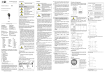
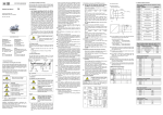
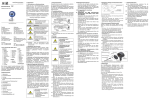
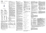
EN 2. Product Identification 1.1 Information concerning the user manual The type plate serves to identify the device. The most important data can be taken from this. The order code is used for unique identification of your product. Follow the safety and handling instructions that are set out in this user manual. Compliance with the applicable accident prevention regulations and safety regulations as well as with national installation standards and recognized codes of practice must also be ensured. Original User Manual - 1. General Information Measure- Type designation ment range Order code Serial number This user manual is part of the device and should be kept accessible to personnel at all times in the immediate vicinity of the installation location of the device. Pressure transmitter with IO Link interface The device should be electrically connected immediately after installation to ensure that no moisture is able to penetrate into the plug connector, If this is not possible, the ingress of moisture must be prevented by using a suitable protective cap. (The protection class specified in the data sheet applies to the connected device.) Select an installation position that allows splashed water and condensation to drain away. Ensure that sealing surfaces are not exposed to standing liquid! Install the device such that it is protected from direct sunlight. In the worst case, direct sunlight may result in the maximum permissible operating temperature being exceeded, which can then damage the device or affect its ability to function correctly. If the internal pressure in the device rises, this could also cause temporary measurement errors. Take care that the pressure connector is not subjected to any mechanical stresses higher than that permitted, since this could cause the characteristic to shift or result in damage. This applies especially to very small pressure ranges, as well as to devices with a pressure connector made of plastic. In the case of hydraulic systems, orient the device such that the pressure connector faces upwards (for venting). Provide a cooling section when using the device in steam lines. If there is a risk that a device installed outdoors might be damaged by lightning strike or overvoltage, we recommend the provision of overvoltage protection between the power supply unit or control cabinet and the device. If the device is installed with the pressure connector facing upwards, make sure that no liquid runs down the housing. This could result in moisture and dirt blocking the gauge reference in the housing and cause malfunctions. If necessary, remove any dust and dirt from the edge of the screw joint of the electrical connector. - - – Subject to technical alteration – DCT 133, DCT 143, DCT 163 DCT 533, DCT 563 1.2 Symbols used - Nature and source of danger Measures to prevent danger Warning term Signal Supply Pin configuration Fig. 1 Type plate The type plate must not be removed from the device! Warning term DANGER DCT 533 WARNING www.bdsensors.com CAUTION Headquarters BD SENSORS GmbH BD-Sensors-Str. 1 D - 95199 Thierstein Germany Tel.: +49 (0) 9235-9811-0 Fax: +49 (0) 9235-9811-11 Eastern Europe BD SENSORS s.r.o. Hradištská 817 CZ - 687 08 Buchlovice Czech Republic Tel.: +42 (0) 572-4110 11 Fax: +42 (0) 572-4114 97 China BD SENSORS China Co, Ltd. Room B, 2nd Floor, Building 10, No. 1188 Lianhang Rd. 201112 Shanghai, China Tel.: +86 (0) 21-51600 190 Fax: +86 (0) 21-33600 613 Russia BD SENSORS RUS 39a, Varshavskoe shosse RU - Moscow 117105 Russia Tel.: +7 (0) 95-380 1683 Fax: +7 (0) 95-380 1681 You can find our offices in EUROPE • • • • • • • • • • • • • Belgium Denmark England Finland France Greece Italy Lithuania Luxembourg Netherlands Norway Poland Portugal Romania Sweden Switzerland Slovakia Spain Turkey Ukraine AFRICA • Egypt • South Africa • • • • • • • • • • • India Iran Israel Japan Kazakhstan Korea Malaysia Singapore Taiwan Thailand Vietnam AUSTRALIA The addresses of our overseas offices can be found at www.bdsensors.de. Data sheets, user manuals, ordering codes and certificates are also available for you to download from our website. Table of contents 1. General Information 2. Product Identification 3. Installation 4. Electrical Installation 5. Commissioning 6. Operation 7. IO-Link Interface 8. Decommissioning 9. Maintenance 10. Servicing/Repair 11. Disposal 12. Guarantee Conditions 13. Declaration of Conformity / CE Immediate danger! Failure to observe will result in death or serious injury. 3. Installation 3.1 Installation and safety instructions Danger of death from electric shock Possible danger! Failure to observe may result in death or serious injury. DANGER - Install the device only when the machine is depressurized and the power supply has been switched off! Danger of death from improper installation Dangerous situation! Failure to observe may result in slight or moderate injury. WARNING - Installation must be performed only by appropriately qualified specialist personnel who have read and understood the user manual. NOTE – Tips and information for the user in order to ensure trouble-free operation. Oxygen 1.3 Qualification of personnel DANGER Work on electrical components must be performed only by a qualified electrician and in accordance with the applicable regulations and guidelines. 1.4 Limitation of liability and warranty - Failure to follow the instructions or observe technical regulations, improper use or use of the device in a manner other than that intended, or alteration or damage to the device will void the warranty and invalidate claims for liability. - - The Pressure transmitters DCT xx3 with-IO_Link interface have been developed for pressure measuring applications depending on the particular model. Depending on the particular device and mechanical connection, they are suitable for a wide range of applications. The pressure sensor is intended for installation in a machine or system. It is the responsibility of the user to check whether the device is suitable for the chosen application. If in doubt, please contact our sales office. BD SENSORS cannot, however, assume any liability for an incorrect choice or any consequences arising from this! - Media that can be measured are gases or liquids that are compatible with the materials that contact the medium. These are described in the data sheet. Furthermore, it must be ensured in each individual case that the medium is compatible with the parts the come in contact with it. - The technical data as set out in the current data sheet are authoritative. If you do not have the data sheet, please request it from us or download it from our website. WARNING Danger of death through incorrect use - In order to avoid accidents, use the device only in accordance with its intended use. 1.6 Package contents Check that all of the listed parts are included in the delivered package and have been supplied in accordance with your order: - Pressure transmitters from the DCT xx3 series - For DIN 3852 mech. connectors: O-ring (pre-fitted) - User manual 3.2 General installation instructions Danger of death from explosion through improper use of devices intended for use with oxygen Installation, commissioning, operation, maintenance, decommissioning and disposal may be carried out only by appropriately qualified specialist personnel. 1.5 Intended use ASIA • • • • • • • Meaning - - - - - The following points must be observed in order to ensure safe handling: Make sure that a special version of your device has been ordered for use with oxygen and that the expected device has been delivered. The easiest way for you to verify this is by checking the type plate (see Fig. 1 regarding this). If your order code ends with the digits "007", then your device is suitable for oxygen applications. When it is delivered, the device is packaged in a plastic bag to protect it from contamination. Take note of the advice sticker with the text "Device for oxygen; unpack immediately before installation"! Also note that contact with skin should be avoided when unpacking and installing the device so as to avoid leaving grease residues on the device. The relevant provisions concerning explosion protection must be met during installation. Also check whether approval as intrinsically safe equipment is required in addition to suitability for oxygen. (This is not the case for the device as supplied!) Please note that the entire system must comply with the requirements of the BAM (German Federal Institute for Materials Research and Testing, DIN 19247). Pressure transmitters designed for use without seals are recommended for oxygen applications > 25 bar. Pressure transmitters with 70 EPDM 281 sealing rings: Maximum permitted values: 15 bar / 60° C and 10 bar / 60° C to 90° C (BAM approval). Pressure transmitters with FKM (Vi 567) sealing rings: Maximum permitted values: 25 bar / 150° C (BAM approval). Please treat this highly sensitive electronic measuring instrument carefully, both when packed and when unpacked! No modifications or alterations may be made to the device. Do not throw or drop the device! Only remove the packaging and, if applicable, the protective cap from the device shortly before its installation, so as to avoid damaging the diaphragm. Be sure to retain the supplied protective cap! Fit the protective cap back over the diaphragm immediately after dismounting the device. Treat the unprotected diaphragm with extreme care; it can be damaged very easily. Do not apply any force to install the device so as to avoid damaging the device and the system! When installing outdoors or in humid environments, the following points should be noted: - Carefully remove the device from its packaging and dispose of the packaging properly. - Then proceed as described in the following installation instructions. 3.3 Installation instructions for DIN 3852 connectors - - - DO NOT USE ANY ADDITIONAL SEALING MATERIALS SUCH AS TOW, HEMP OR TEFLON TAPE! Check that the O-ring is undamaged and is seated in the groove provided for it. Make sure that the sealing surface of the receiving part is perfectly clean and smooth. (RZ 6,3) Screw the device into the mounting thread by hand. If you have a device with a knurled ring, the device need only be screwed in by hand. Devices with wrench flats must be tightened with an open-end wrench (with steel wrench flats: G1/4": approx. 5 Nm; G1/2": approx. 10 Nm; G3/4": approx. 15 Nm; G1": approx. 20 Nm; with plastic wrench flats: max. 3 Nm). The specified tightening torques must not be exceeded! 3.4 Installation instructions for EN 837 connectors - Use a suitable seal that is compatible with the process medium and the pressure to be measured (e.g. a copper seal). - Make sure that the sealing surface of the receiving part is perfectly clean and smooth. (RZ 6,3) - Screw the device into the mounting thread by hand. - Then tighten it with the open-end wrench (for G1/4": approx. 20 Nm; for G1/2": approx. 50 Nm). - The specified tightening torques must not be exceeded! 3.5 Installation instructions for NPT connectors - Additional seal materials, e.g. PTFE tape, may be used to provide sealing. - Screw the device into the mounting thread by hand. - Then tighten it with the open-end wrench (for 1/4" NPT: approx. 30 Nm; for 1/2" NPT: approx. 70 Nm). - The specified tightening torques must not be exceeded! 3.6 Installation instructions for dairy pipe connectors - Check that the O-ring is undamaged and is seated in the groove provided for it in the receiving fitting. - Center the dairy pipe connector in the corresponding receiving fitting. - Screw the union nut on to the receiving fitting. - Then pull it tight with a hook wrench. 3.7 Installation instructions for clamp and Varivent connectors - Use a suitable seal that is compatible with the process medium and the pressure to be measured. - Place the seal on the corresponding receiving fitting. - Center the clamp or Varivent connector above the corresponding receiving fitting with its seal. - Then attach the device using a suitable fastening element (e.g. semi-ring or retractable ring clamp) in accordance with the manufacturer's instructions. The sensor must not be exposed to high temperatures or rapid pressure increases that exceed the specified limits (see data sheet for limit values). The sensitive diaphragm of the flush-mounted sensor must not be touched since it may deform or tear. 4. Electrical Installation Danger of death from electric shock - Switch off the power supply before installing the device. WARNING Electrically connect the device in accordance with the specifications given on the type plate, the following pin assignment table and the connection diagram. Pin assignment table: Electrical connections M12x1 (4-pin) metal Binder 723 (5-pin) cable colours (DIN 47100) 1 3 4 1 3 4 wh (white) bn (brown) gn (green) housing housing ye/gn (yellow / green) Supply + Supply – SIO / IO Link + Shielding Connection diagrams: 3-wire system (SIO / IO-Link) For the installation of a device with cable outlet following bending radiuses have to be complied with: cable without ventilation tube: static installation : 5-fold cable diameter dynamic application: 10-fold cable diameter cable with ventilation tube: static installation : 10-fold cable diameter dynamic application: 20-fold cable diameter the damage or removal of the PTFE filter which is fixed over the end of the air tube on devices with cable outlet and integrated air tube. If possible, use a shielded and twisted multicore cable for the electrical connection. If a transition is desired from a transmitter cable with gauge tube to a cable without gauge tube, we recommend our terminal box KL 1 or KL 2. 5. Commissioning Before using the device for the first time, check that it has been properly installed, and make sure that it does not show any visible defects. The device may by commissioned only by appropriately qualified specialist personnel who have read and understood the user manual. 7. IO-Link Interface 7.5 Parameter data 7.1 General device information The parameter data for the pressure sensor correspond to the Smart Sensor profile. Baud rate COM 2 (38.4 kbaud) Input process data length 2 bytes Minimum cycle time 5 ms IO-Link version V 1.1 SIO mode Yes 8. Decommissioning Danger of injury from media escaping under pressure Index hex Subindex hex Object name Single value Default 0x02 0x00 System commands 0x81 = Delete min/max value 0x82 = res 0xA0 = Set0 0x03 0x00 Data Storage Index 0x01: Upload Start 0x02: Upload End 0x03: Download Start 0x04: Download End 0x05: Data Storage Break Comment The action is executed by writing in the subindex 7.2 SIO mode (standard IO mode) In this mode the sensor operates like a normal pressure sensor with standard output signals. The digital output is always on Pin 4 of the M12 connector plug or over green cable. 7.3 IO-Link mode (communication mode) 0x0C 0x00 Device Access Lock The pressure sensor switches to the IO-Link communication mode, when it operates under an IO-Link master. IO-Link communication is only possible over Pin 4 of the M12 connector plug or over green cable. 7.3 Process data The process data length of the sensor is 16 bits. The switch state (BCD1) as well as the current measured values are transmitted. The 14 bits of the measured value are scaled according to the measuring range. 15 bit 14…2 1 0 Signed bit Measured value 0 BDC1 / Output 1 7.3 Error codes 0x24 Error code Description 0x8011 Index not available 0x8012 Subindex not available 0x8023 Access denied 0x8030 Parameter value out of range 0x8033 Parameter length overrun 0x8034 Parameter length underrun 0x3D 0x00 0x02 Device status SwitchPoint mode Danger of injury from the measured medium WARNING 0x00: Unlocked 0x01: IO-Link Lock 0x02: Data Storage Lock 0x04: Parameterization Lock 0x08: User Interface Lock 0x03: IO-Link Lock + Data Storage Lock 0x05: IO-Link Lock + Parameterization Lock 0x09: IO-Link Lock + User Interface Lock 0x06: Data Storage Lock + Parameterization Lock 0x0A: Data Storage Lock + User Interface Lock 0x07: Data Storage Lock + IO-Link Lock + Parameterization Lock 0x0B: Data Storage Lock + IO-Link Lock + User Interface Lock 9. Maintenance The device is, in principle, maintenance free. If necessary, the housing of the device may be cleaned with a damp cloth and a non-aggressive cleaning solution while it is switched off. With certain media may, however, deposits or contamination may accumulate on the diaphragm. The specification of appropriate maintenance intervals for inspection.is recommended in this case. Once the device has been properly decommissioned, the diaphragm can normally be cleaned with a non-aggressive cleaning solution and a soft brush or sponge. Care should be taken while doing so. If the diaphragm is covered in limescale, decalcification by BD SENSORS is recommended. See the Servicing/Repair section with regard to this. 0x00 Device is operating properly 0x02 Out-of-Specification 0x04 Failure 0x80: Hysteresis NO 0x81: Hysteresis NC 0x82: Window NO 0x83: Window NC Event codes for IOLink 1.0 Device status Type No malfunction 0x0000 0x0000 0 Notification General malfunction Unknown error 0x1000 0x1000 4 Error Process variable range overrun Process data uncertain 0x8C10 0x8C10 2 Warning Process variable range underrun Process data uncertain 0x8C30 0x8C10 2 Warning Index hex 0x3C 0x3C 0xD0 0xD1 0xD5 0xD6 0xD7 Subindex hex 0x01 0x02 0x00 0x00 0x00 0x00 0x00 Object name SetPoint 1 = SP1 SetPoint 2 = rP1 Switching Delay Time 1 Resetting Delay Time 1 Min Pressure Value Max Pressure Value Measurement Damping - Depending on the measured medium, suitable precautions should be taken, e.g. protective gloves, goggles. 0x00: Unlocked The device must be disposed of in accordance with European Directives 2002/96/EC and 2003/108/EC (Waste Electrical and Electronic Equipment). Waste electrical products may not be disposed of with household waste! Depending on the medium used, residues on the device may constitute a hazard to the environment. You should therefore take appropriate precautions if necessary and dispose of the device properly. 12. Guarantee Conditions The guarantee conditions are subject to the statutory warranty period of 24 months, starting from the date of dispatch. No warranty claims will be accepted if the device has been used improperly, modified or damaged. The warranty does not cover damaged diaphragms. Warranty cover also excludes any claims for defects that have arisen as a result of normal wear. 13. Declaration of Conformity / CE The supplied device fulfills the statutory requirements. The relevant directives, harmonized standards and documents are listed in the EU Declaration of Conformity applicable to the product. This can be found at http://www.bdsensors.de. In addition, the operational safety of the device is confirmed by the CE mark on the type plate. Incorrect cleaning can result in irreparable damage to the measuring cell. For this reason, you should never use sharp objects or compressed air to clean the diaphragm. 0x80: HNo 10. Servicing/Repair 10.1 Recalibration 7.4 Event codes Event codes for IOLink 1.1 WARNING - Dismount in an orderly fashion when the machine is depressurized and the power supply has been switched off. - Check whether the medium needs to be drained before dismounting! 11. Disposal Access Length Value range R/W R/W R/W R/W R R R/W 2 bytes 2 bytes 2 bytes 2 bytes 2 bytes 2 bytes 2 bytes Process Data Process Data 0..500 0..500 Process Data Process Data 0…1000 in 10 ms steps Gradient Unit Default 0.1 0.1 sec sec 100% 0% 0 0 1 ms 0 It is possible that the offset value or the scaling value may shift during the lifetime of the device. This is indicated by a deviation in the output signal value with reference to the set measurement range start or end values respectively. If either of these two phenomena should occur after a prolonged period of use, recalibration is recommended in order to ensure a continued high level of accuracy. 10.2 Return Whenever the device is returned, no matter whether for recalibration, decalcification, modification or repair, it must be carefully cleaned and packed such that there is no risk of breakage. The device must be accompanied by a notice of return giving a detailed description of the fault. If your device has come into contact with pollutants, then a notice of decontamination will also be needed. You can find the relevant templates on our website at www.bdsensors.de. Should you send in your device without a notice of decontamination and doubts with regard to the medium used should arise in our service department, repair work will commence only once an appropriate notice has been received. Caution Danger of injury from pollutants - If the device has come into contact with pollutants, wear suitable protective clothing, e.g. gloves, goggles, when cleaning it. BA_DCT-IO-Link_E _250814