1
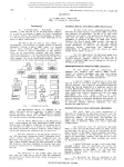
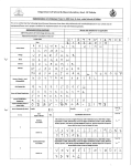
LC-1
lrrigation tirner
User's manual
-LEGO'
IRRIGAIION EOUIPMEIIT
LC-1 ASSEMBLY INSTRUCTIONS.
PER COVER
CONTROLLER
LOWER COVER
SCREWS
I\4OUNTING BRACKET
RELEASE LEVER
MANUAL OVERRIDE
ACTUATOR
O-RING
Make sure
do not loose it
FLOW
DIRECTION
PLASTIC VALVE
VALVE ASSEMBLY
Screw the agualQl clockwise until it reaches the bottom of the cavity.
NOTE: a small O-RING (Parker Nq 2-006) must first be inserted as shown
DO NOT USE TOOLS TO TIGHTEN THE ACTUATOR.
DO NOT OVER TIGHTEN IT.
Connect the valve assembly to the water line.
Make sure that flow arrow on the valve shows the right llow
direction.
Once connected to the water system, turn on the water to
detect eventual leakage ( OPEN and CLOSE the va ve with
the actuaior manual override ). Return the overrlde to AUTO.
Please note: you have to turn the red arrow all the way 1804
to the desired position.
CONTROLLER ASSEMBLY
for valve mounting only )
Connect the mount ng bracket to the back ol the
controller !s ng the 4 screws.
(
FINAL ASSEMBLY
Place the controller assembly over the actuator until
snaps into position. lvlake sure the actuator wire is
free and clear oui of the bracket.
it
WIRE CONNECTION
Do not remove the rubber plug on the bottom of the
controller. Use the hardened tip oi the wire to punch
a hole in it and thread the w res through. Usrng a
coin, remove the lower cover and connect the wires
to the terrninal blocks as shown below. CONNECT
THE BLACK & WHITE wire to "+' (Plus) and the
BLACK wire to "-' (N/inus).
BATTERY CONNECTION
(Battery not supplied)
connect a 9v ALKALINE battery and place it into its
compartment. The display will flash 3 times showing
all the segments followed by the "OFF" command ,
resetting the actuators to the "CLOSE" position.
Close the lower cover.
WALL MOUNT
l\4ount the unlt on a wall by sliding the 2
slots found on the back of the unit over
2 screw heads, place 90mm apart.
WALL MOUNT
IMPORTANT INFORMATION
. The
button leads you through the programming steps.
. lf you are losl or wish to go to
continuously for a few seconds until display shows
o'""
l$il
which is the automatic
asaln to advance to
running stage.
e,..r.
[Eil
to start prosrammins asain
. Auto return. ll within 3 minutes, you do not touch any button, the controller
will automatically go to
. lf you press
. Setting reset : il you
continuously, the digits will advance quickly.
0,...
ffil
*o
m
simultaneously,
the digits will reset back to "0".
. Watering days can be programmed in two ways:
1. You can identify the day ol the week lor watering (SUN, MON,
TUE etc...)
2. You can choose the number of days'interval between waterings
(a 2 day cycle means that the watering will take place every two
days.)
CONTROL PANEL
SUN MON TUE WED/THU FRY SAT
"#
12:00
CONTROL BUTTONS
1
. NEXT STEP button
Used to advance program steps.
2. DAY /. STN button
Used to advance DAYS or STATIONS.
DISPLAY INDICATORS
5, DAYS OF THE WEEK.
6. PROGRAM STEPS INDICATOR.
7.
BAfi:
indicates low battery.
3. HRS / ON button
Used to change HOURS or "ON"
function.
9. OFF: The controller is in RAIN-OFF mode.
4. MIN / OFF
Used to advance I/INUTES or "OFF"
function.
10. DAY CYCLE : indicates irrigation
programming by interval of days between
waterings.
8. STATIONS ne indicators.
PROGRAM STEPS
to set loday's day
@
to set the present hour
to set the minules
to advance to the nexl program
E@
Press
0:30
'X
Press
step
EEEIEEEE
to set the hours of lhe watering duration lol this station
to set the minuies
-
to advance to lhe next Program step
ii you do not want to irrigate on the flashing day
E@
to irrigate on the flash ng day
Press
to stav w thlOR lpt.r.
[ffi the
ffi
weekly
I
*=
to select Your DAY CYCLE:
I
SqlCqLl
DAY CYCLE
To resel back to 0,
prtt.
ffi
@
@
IEE
Press
ffi
to set the hours ol the l rst starting time for lhls stalion
Press
ffi
to set the minules.
Press
i@
ro advance 10 lne nexl
addit onal
E@;.v.:
I
a
to advance to the next program step
Eil7:oo
th s stat on wi
operate every day
Select 2 this station will
operate every 2nd day
Sgleqllthis stalion w ll
operate every 3d day
prog'a- step and program
walering slans rol tlis slat'o1 on the sa-e day
to advance to the next program
.t.p EEIEII
Press
[S
Press
to ooer tre va.ve o'tqe'lasl-i19 slatiol
fPl
tagu,
Press
ffi
to close the valve
Press
[ffl
to eo to AUro-RUN / oFF
GENERAL INFORMATION
Baltery replacement.
As soon as the low battery indicator BATT llashes, the 9V battery must be replaced.
After battery disconnection the program will remain in memory for 10 seconds until
reconnection to the new battery.
0perating conditions.
The controller is designed for outdoor operatlon. However it is recommended to place it in a
protected area.
Keep the cover closed at all times,
ln winter, the controller can be removed from the valve and stored indoors for better
protection, Only the actuator wires should be disconnected.
By keeping the battery connected, the program will remain in memory until reconnection of
the controller.
Manual ovenide.
The manual override allows you to open or close the valve mechanically. The actuator is
..--.' ' .-'....
factory set on
.. .
AUTO.
_
.
i
to clilse
TO CLOSE THE VALVE: Turn the arrow
CLOCKWISE 180a and return it back
to AUTO; the valve is closed.
TO'LOCK" THE VALVE: lf you wish
to keep the valve in either OPEN or
CLOSED position, keep the arrow
pointed in 180" d:reclon without returning
it to AUTO in any of the 2 previous steps.
TO RESUIVE AUTO[/ATIC OPERATION:
return the arrow to AUTO.
.
'1Qos
TO OPEN THE VALVE: turn the arrow
COUNTER-CLOCKWISE, 1 804 and return
it back to AUTO; the valve is open.
z,
o-\
Design and engineering:
LEGO IRRIGATION
ISRAEL
Printed in lsrael
Distributed by: