1
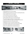
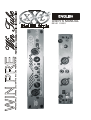
PROFESSIONAL 2 CHANNEL SOLID-STATE MIC / LINE PREAMPLIFIER
USER’S MANUAL
REV.01 11/2001
SAFETY INSTRUCTIONS
This symbol, wherever it appears,
alerts you to important operating and
maintenance instructions in the
accompanying literature. Read the
manual.
Detailed Safety and Operation Instructions:
All the operation instructions and safety should be read before the machine is operated.
Follow instructions:
All operation and user instructions should be followed by the user or the installer.
Retain Instructions:
The safety and operating instructions should be carefully retained for future reference.
Heed Warnings:
All warnings on the machine and in the operating instructions should be adhered to.
Water and Moisture:
The machine should not be used near water or in place full of moisture.
Ventilation:
The machine should be placed so that its location does not interfere with its proper ventilation. For
example, the appliance should not be situated on a bed, carpet, or similar surface that may create an
obstacle for the ventilation openings: or placed in a built-in installation, such as a bookcase or cabinet that
may impede the flow of air around the machine.
Heat:
The machine should be situated far away from heat sources such as heat registers, radiators, stoves, or
other machines (including amplifiers) that produce heat.
Power Source:
The machine should be connected to a power supply only of the type described in the operating
instructions or as marked on the external power transformer.
Power-Cord Protection:
Power supply cord should be routed so that it is not likely to be walked on or pinched by items placed
upon or against it, paying particular attention to cords, power transformer and plugs and the point where
they exit from the appliance.
Cleaning:
The machine should be cleaned only as recommended by the manufacturer.
Non-use Periods:
The external power transformer should be unplugged from the outlet when left unused for a medium or
long period of time.
Object and Liquid Entry:
Care should be taken so that objects do not fall and liquids are not spilled into the enclosure through
openings, do not leave bottles or cans upon the unit.
Damages that Require Service:
The unit should be serviced by qualified service personnel in the following cases:
1. The external power transformer, power supply cord or the plug has been damaged.
2. The enclosure of the unit has been damaged.
3. The unit has been exposed to water or moisture.
4. The unit does not appear to operate normally or exhibits a marked change in performance.
5. Objects have fallen, or liquid has been spilled into the unit.
Servicing:
The user should not attempt to service the unit beyond what is described in the Operating Instructions. All
other servicing should be referred to qualified and authorized service personnel.
2 – WIN PRE & WIN TUBE
USER’S MANUAL
WIN PRE / WIN TUBE
PROFESSIONAL DUAL CHANNEL MIC / LINE PREAMPLIFIER
9 High Grade Microphone and Line Preamplifier.
9 WIN TUBE employs high quality Vacuum Tubes for outstanding Audio quality.
9 Output adjustable Limiter to prevent clipping.
9 Ultra low distortion and noise at any output level.
9 Low cut filter for anti-pop function on microphones.
9 RCA and balanced XLR connectors for multi-standard wiring.
9 Servo-balanced Inputs and Outputs to avoid noise problems
9 Ultra-low noise 4580 audio op-amps for outstanding sound performance
9 High-quality potentiometers and illuminated switches
9 High-quality, low tolerance components for highest results.
9 Full Aluminium rugged construction ensures long life and durability
9 External power supply design for professional applications
9 Battery use possibility with external dedicated battery pack
3 – WIN PRE & WIN TUBE
USER’S MANUAL
TABLE OF CONTENT
1. INTRODUCTION
p. 4
1.1 High Technology
p. 4
2. THE DESIGN
p. 4
2.1 The GAIN control
2.2 The LOW CUT switchl
2.3 The 48V PHANTOM switch
p. 5
p. 5
p. 5
3. INSTALLATION
p. 6
3.1 Packaging
3.2 Rack mounting
3.3 Mains voltage
3.4 Audio connections
Fig. 3.1: Different Connector Types and Wiring
Fig. 3.1: Different Connector Types and Wiring
p. 6
p. 6
p. 6
p. 6
p. 7
p. 8
4. CONTROLS
p. 9
Fig.4.1 Front panel controls
Fig. 4.2 Back panel connections
p. 9
p. 10
5. APPLICATIONS
p. 11
5.1 During Recording
5.2 Live Situations
Fig. 5.1 Studio Recording application
Fig. 5.2 Live application
p. 11
p. 11
p. 12
p. 12
6. TECHNICAL SPECIFICATIONS
p. 13
4 – WIN PRE & WIN TUBE
USER’S MANUAL
1. INTRODUCTION
The XXL WIN TUBE and WIN PRE are the perfect choice as first ring of your audio
chain both for Live and Studio applications. These ultra-low noise high-grade two
channel mic/line preamplifiers will support you to record the most complex of
instrumental and vocal tracks with even more detail and resolution. The WIN TUBE it is
able to add that warm, musical sound that can only come from real tube. You can
connect these units directly to your mixing console, direct to disk recorder, DAT or
sampler. In the WIN TUBE we integrated a selected 12AX7 vacuum tube in the
preamplifier, fusing tradition and innovation, further developing traditional tube circuitry
and adapting it to blend with modern professional audio technology. Our input circuit
technology for preamplifier input stage allows minimizing common mode noise, also
with ultra low level signals. An over fast, smooth limiter stage ensure to prevent
clipping all every kind of units connected to the output of the WIN TUBE (i.e.: Analog to
Digital converters). The limiter threshold is adjustable from the back side of the module.
Two accurate Led bar meters ensure you good check possibility for input signal levels.
Two LEDs on the front panel indicate the activity of the limiter section. The exclusive
XXL BluAl Full Aluminium ultra-light Half Rack Frame allows you to save drastically
space and weight and to fit your unit, very easily, both in standard 19“ Rack and in new
generation 9.5” Rack.
1.1 High Technology
Our experience in the field of professional studios drove us to design the WIN PRE and
WIN TUBE, two incredible small size dual channel preamplifiers that are able to give
answer to all the demands in Studio, Live, broadcast and TV applications. All the
electronics is assembled directly on PCB with no wires use, it means less possibility of
malfunction. All the internal IC are 4580, ultra High quality Operational Amplifier that
allow high current output with very low noise threshold. All the output are protected in
order to guarantee safe operating conditions in every situation. All the inputs are
balanced, in this way you can have the best matching conditions with the other
machines. The choice of having the external power supply ensure professional features
with minimum noise, and allow you to drive the unit also with an external optional
battery pack to use the unit also without the presence of main AC power.
5 – WIN PRE & WIN TUBE
USER’S MANUAL
2. THE DESIGN
2.1 The GAIN control
The GAIN potentiometer allows setting the proper level of the input signal in order to
not overdrive the internal stages of the unit. Verify on the VU meter that the level is
correct (around 0 dB) otherwise adjust the level using the GAIN potentiometer.
2.3 The LOW CUT switch.
The LOW CUT switch, when pressed allows routing of the input signal to a high pass
filter stage that provides to cut out all the extra low frequencies (under 100 Hz); this is
very useful to avoid the “pop” effect of the most part of the vocal microphones and the
low frequency wind noise in outdoor use of the most part of microphones.
2.4 The 48V PHANTOM switch.
Pushing this switch you give power to the inside Phantom Power generator stage that is
able to provide over clean and noiseless 48V power on both the two microphones input
of the device. This function is to be used to feed almost every kind of condenser
microphones and every other device that need phantom power to work. Do not press
this switch if you connect to one or both mic inputs a device that can be damaged by
the presence of phantom power.
6 – WIN PRE & WIN TUBE
USER’S MANUAL
3. INSTALLATION
3.1 Packaging
XXL carefully pack in the factory all its units and the packaging was designed to protect
the unit from rough handling. Nevertheless, we recommend that you carefully examine
the packaging and its contents for any signs of physical damage, which may have
occurred in transit.
ATTENTION!
If the unit is damaged, please do not return it to us, but notify your dealer and the
shipping company immediately, otherwise claims for damage or replacement may
not be granted. Shipping claims must be made by the consignee.
3.2 Rack mounting
The unit fits into one new standard “half rack” unit of space (1 3/4"). Please allow at
least an additional 4" depth for the connectors on the back panel. Be sure that there is
enough air space around the unit for cooling and please do not place the unit on high
temperature devices such as power amplifiers to avoid overheating. It is also possible
to fit the unit into one standard rack unit of space (1 3/4") using the optional RK100 rack
adapter that you can buy from your Dealer.
3.3 Mains voltage
Before you connect your unit to the mains AC socket, please make sure that your local
voltage matches the voltage required by the external power supply of your unit! In case
that the label of your Unit transformer require a voltage different from the one that you
have in your Country do not connect it to mains and contact your Dealer.
3.4 Audio connections
The jack inputs of the unit are fully balanced. If possible, connect the unit to other
devices in a balanced configuration to allow for maximum interference immunity.
Please ensure that only qualified persons install and operate the unit. During
installation and operation the user must have sufficient electrical contact to
earth. Electro-static charges might affect the operation of the unit!
7 – WIN PRE & WIN TUBE
USER’S MANUAL
Unbalanced use of mono
1/4” jack connector
Tip = Signal
Balanced use of stereo
1/4” jack connector
Tip = Hot
(In Phase)
Ring = Cold
(Out of Phase)
Sleeve =
Ground / Shield
Sleeve =
Ground / Shield
Tip = Signal
Sleeve =
Ground / Shield
Cable Clamp
Tip = Hot
(In Phase)
Ring = Cold
(Out of Phase)
Sleeve =
Ground / Shield
Cable Clamp
Fig. 3.1: Different Connector Types and Wiring
8 – WIN PRE & WIN TUBE
USER’S MANUAL
Balanced use male
XLR connector
Unbalanced RCA
connector
Tip = Signal
Sleeve =
Ground / Shield
Tip = Signal
Sleeve =
Ground / Shield
Pin1 = Ground / Shield
Pin2 = Signal + (hot)
Cable Clamp
Pin3 = Signal - (cold)
Fig. 3.2: Different Connector Types and Wiring
9 – WIN PRE & WIN TUBE
USER’S MANUAL
4.1 CONTROLS
11 12
1
2
3
4
13 14
5
6
7
8
9
10
Fig.4.1 Front panel controls
1) MICROPHONE INPUT of CH1 allows connecting to the first channel almost every kind of
microphones or DI box.
2) This is the balanced LINE INPUT of the CH1 you can directly plug in Guitars, basses, keyboards, midi-machines and so on.
3) The LOW CUT switch of CH1 cuts out over bass from the signal of this channel.
4) The LEVEL meter of CH1 allows continuous monitoring of the input level of this Channel.
5) The 48V PHANTOM power switch if pressed give phantom to both the Mic inputs.
6) The LEVEL meter of CH2 allows continuous monitoring of the input level of this Channel.
7) The LOW CUT switch of CH1 cuts out over bass from the signal of this channel.
8) This is the balanced LINE INPUT of the CH1 you can directly plug in Guitars, basses, keyboards, midi-machines and so on.
9) MICROPHONE INPUT of CH2 allows connecting to the first channel almost every kind of
microphones or DI box.
10) The POWER ON switch is the main power switch and allows you switching on /off the
device.
11) LIMIT LED shows that the Limiter of the CH1 is working, this means that the input signal is
over passing the set Threshold (see Fig. 4.2)
12) The GAIN control of the CH1 allows the right setting of the input level of the signal of this
channel.
13) The GAIN control of the CH2 allows the right setting of the input level of the signal of this
channel.
14) LIMIT LED shows that the Limiter of the CH2 is working, this means that the input signal is
over passing the set Threshold (see Fig. 4.2)
10 – WIN PRE & WIN TUBE
MANUAL
USER’S
1 2
3
4
5
6
Fig. 4.2 Back panel connections
1) MAIN POWER SUPPLY SOCKET. Use only original power supply. Read carefully
the SAFETY INSTRUCTIONS before connecting the device.
2) This clip is the holder for the power supply cord, fix the cable to avoid undesired
unplugging.
3) The CH2 BALANCED SPLIT OUT is the +4 dBu XLR output of the CH2. It is
possible to connect both in balanced and in unbalanced mode this output.
4) This are the unbalanced outputs of the device. Their standard level is –10 dBV.
5) The CH1 BALANCED SPLIT OUT is the +4 dBu XLR output of the CH2. It is
possible to connect both in balanced and in unbalanced mode this output.
6) The LIMITER THRESHOLD control allows setting the threshold level of the limiter
stage of the device. One set every audio signal that will over-pass the threshold will
be padded. If the Limiter is not desired set the Limiter Threshold control to max.
11 – WIN PRE & WIN TUBE
MANUAL
USER’S
5. APPLICATIONS
5.1 During recording.
Every time you are recording your goal is to achieve a natural sound image of high
quality in the first place. Any reverb, chorus, delay or other effects can be add later
during the mixdown, without affecting the recorded material. First of all set a gain level
that suits the input material by moving the GAIN control of the desired channel. Than
be sure to take all measures that enable you to achieve the best sound possible: verify
the microphone position in the room to match the result you need in consideration to
the room acoustic. Than, if required, set the Limiter Threshold control on the back panel
of the device to prevent recorder clipping. Now you can start recording.
5.2 Live situations.
Of course both WIN-TUBE and WIN-PRE are the perfect choice as the first ring of your
audio chain also in live performances. In this case you can in fact improve the quality of
the sound of your microphone or of your acoustic instrument by the use of these
preamplifiers before the input of your mixer. Follow the some suggestions sow for
recording setting in chapter 5.1 concerning Gain and Limiter Threshold setting.
12 – WIN PRE & WIN TUBE
MANUAL
USER’S
Fig.5.1 Studio recording application
13 – WIN PRE & WIN TUBE
MANUAL
USER’S
Fig.5.2 Live application
14 – WIN PRE & WIN TUBE
MANUAL
USER’S
6. TECHNICAL SPECIFICATIONS
AUDIO INPUT
Connectors XLR Type RF filtered, servo-balanced input
Impedance 2 kOhms balanced, 1 kOhm unbalanced
Max. Input Level +4dBu balanced and unbalanced CMRR typ. 40dB, >55dB @ 1 kHz
1/4" jack
AUDIO OUTPUT
Connectors XLR and 1/4" jack
Type Electronically servo-balanced output stage (optional transformer-balanced).
Automatic
level correction for unbalanced use (6 dB).
Impedance 60 Ohms balanced, 30 Ohm unbalanced
Max. Output Level +21dBu, +20dBm balanced and unbalanced
SYSTEM SPECIFICATIONS
Bandwidth 18 Hz to 30 kHz, +/-3dB
Signal-to-noise ratio >100dB, unweighted, 22 Hz to 22 kHz
THD 0.008 % typ. @ +4dBu, 1 kHz, Gain 1
0.04 % typ. @ +20dBu, 1 kHz, Gain 1
IMD 0.01 % typ. SMPTE
Crosstalk <-100dB, 22 Hz to 22 kHz
POWER SUPPLY
30VAC by dedicated adapter or 24 VDC by dedicated battery pack
ADAPTER
Mains voltages USA/Canada ~ 120 V AC, 60 Hz
U.K./Australia ~ 240 V AC, 50 Hz
Europe ~ 230 V AC, 50 Hz
General Export Model ~ 100-120 V AC, ~ 200-240 V AC, 50-60 Hz
Power consumption 10 Watts
PHISICAL
Dimension HALF RACK STANDARD 240mm x 44 mm x 110 mm
Net weight 1 kg around
Shipping weight 2 kg around
15 – WIN PRE & WIN TUBE
MANUAL
USER’S
NOTES:
16 – WIN PRE & WIN TUBE
MANUAL
USER’S
Is a trade mark of HP Sound Equipment srl
via Faentina 169/7 50010 Caldine Florence - ITALY
Tel +39 0555040002 Fax +39 0555040460
Web site: www.x-x-l.it E-mail: info@ x-x-l.it
New materials and design refinements are introduced into existing products without previous notice.
Present XXL Systems may differ in some respects from those presented in this brochure.
17 – WIN PRE & WIN TUBE
MANUAL
USER’S