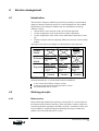
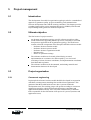
1
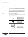
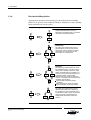
BAAN IV Orgware
Dynamic Enterprise Modeling
User Manual
U7001A US
Document information
Document
Number
Type
Name
Version
Date
: U7001A US
: User Documentation
: Dynamic Enterprise Modeling
:A
: November 1996
© Copyright 1996 Baan Development B.V. All rights reserved
The information in this document is subject to change without notice. No part of this document may
be reproduced, stored or transmitted, in any form or by any means, electronic or mechanical, for
any purpose, without the express written permission of Baan Development B.V.
Baan Development B.V. assumes no liability for any damages incurred, directly or indirectly, from
any errors, omissions or discrepancies between the software and the information contained in this
document.
Dynamic Enterprise Modeling
i
Dynamic Enterprise Modeling
Dynamic Enterprise Modeling
ii
Table of contents
1
1.1
1.2
1.2.1
1.2.2
1.3
Introduction
General
Benefits
Implementation of BAAN IV
Business process re-engineering
Dynamic Enterprise Modeling concept
1.1
1.1
1.2
1.2
1.2
1.3
2
2.1
2.2
2.3
2.4
2.5
2.6
2.7
2.8
2.8.1
2.8.2
2.8.3
Method
Introduction
Scope definition/system boundaries
Business control model
Identification of high-level cross-functional processes (start-to-end)
Main process identification
Brainstorm on options and variants
Main process and detailed process design
Wizard design
Introduction
Characteristics of wizards
Wizard types
2.1
2.1
2.1
2.1
2.3
2.4
2.7
2.8
2.9
2.9
2.9
2.9
3
3.1
3.1.1
3.1.2
3.1.3
3.1.4
3.1.5
3.2
3.2.1
3.2.2
3.2.3
3.2.4
3.2.5
3.2.6
3.2.7
3.2.8
Conventions
Process modeling by means of Petri-nets
Introduction
Petri-net symbols and definitions
Modeling principles
Petri-net building blocks
Petri-net modeling advises
Modeling conventions for the BAAN IV Enterprise Modeler
Introduction
Generic business functions in the repository
Generic business processes in the repository
Business rules in the repository
Static conditions in the repository
Roles in the repository
Utilities in the repository
Wizards in the repository
4
4.1
4.2
4.2.1
4.2.2
4.2.3
4.2.4
4.2.5
Version management
Introduction
Working principle
Baan version
Client kernel team
Client site team
Version management policy
Modification practices
3.1
3.1
3.1
3.1
3.2
3.4
3.5
3.5
3.5
3.6
3.7
3.9
3.10
3.10
3.10
3.11
4.1
4.1
4.1
4.1
4.2
4.2
4.2
4.3
Dynamic Enterprise Modeling
iii
Dynamic Enterprise Modeling
5
5.1
5.2
5.3
5.3.1
5.3.2
5.3.3
5.4
5.4.1
5.4.2
5.4.3
5.4.4
Project management
Introduction
Ultimate objective
Project organization
Concurrent engineering
Resources
Structure of project organization
Project management instruments
Milestone plan
Responsibility chart
Activity schedule
Deliverables
5.1
5.1
5.1
5.1
5.1
5.2
5.2
5.2
5.3
5.4
5.5
5.5
6
Glossary
6.1
Dynamic Enterprise Modeling
iv
About this document
This document explains the Dynamic Enterprise Modeling concept, which is an integral
part of Orgware, Baan’s implementation methodology. The Dynamic Enterprise
Modeling concept deals with all aspects concerning the creation of a reference model
using the Enterprise Modeler tool.
To explain the concept, this document starts with an introduction. Next, the method is
discussed in detail. Then, the modeling conventions are explained. Next, version
management is discussed, and some advises are given. Finally, an explanation is given
of the management of the project in which a reference model is built. The document
concludes with a glossary.
Dynamic Enterprise Modeling
v
Dynamic Enterprise Modeling
Dynamic Enterprise Modeling
vi
1
1.1
Introduction
General
The ever-changing demands of the marketplace force today's companies to keep
reassessing their business processes, organization and technology. This call for
versatility makes strict demands on the information infrastructure, which must
be flexible enough to follow the organizational changes. In addition, modern
information technology (IT) offers important possibilities to support new and
fundamentally different types of organizations (process organization using IT
as enabler).
Baan anticipates these developments by introducing the Dynamic Enterprise
Modeling (DEM) concept, which forms an integral part of BAAN IV Orgware.
Even more explicitly than in the past, the DEM concept places the
implementation of BAAN IV in a process control context. The focus moved
from functionality orientation to a business solution and a business oriented
approach.
The DEM concept has three key objectives:
1
Speed
DEM is based on a short and compact implementation cycle, which
minimizes the implementation effort through the use of modern tools and
business experience.
2
Flexibility
DEM proposes optimization phases after an initial implementation. This
gives all the benefits of a fast implementation while in the following
optimization phases, the BAAN IV configuration smoothly follows
organizational changes without the need for time-consuming and costly
reconfigurations.
3
Integration
The speed and flexibility are accomplished by fully integrating the
Enterprise Modeling tool (BAAN IV Enterprise Modeler) with the
BAAN IV applications. As a result of this integration, most of the
configuration activities are automated. Thus, the Enterprise Modeler is not
only a modeling tool but also a tool to generate the system configuration
and the processes. The tool also functions as the user interface from which
the application can be accessed.
The concept of Dynamic Enterprise Modeling is based on the definition of
generic business models for certain organization typologies. These business
models are not rigid, but can be adapted to specific requirements and future
changes.
Dynamic Enterprise Modeling
1-1
1 Introduction
1.2
Benefits
The predefined organization typology business models (referred to as reference
models) will support the client management in the following two areas:
1
2
1.2.1
1.2.2
Implementation of BAAN IV
Business process re-engineering
Implementation of BAAN IV
Support for pre-sales
Offering, presenting, and evaluating organization typology business models
which closely relate to the customer’s organization, supports the pre-sales
phase of the implementation. This way the focus can be on the solution for
certain kinds of customers and by using their businesses processes, the
solution/application can be made recognizable, which leads to increased
acceptance. This also shows Baan’s commitment and knowledge of the
customer’s business.
Support for the implementation and optimization stages
Offering methods and tools for customizing the generic business model to
the specific needs of the customer, supports the implementation and
optimization of BAAN IV. Based on this customer-specific business model,
the BAAN IV parameters are set and the user-specific menus are created
automatically for each phase. Multiple phases reduce the level of
complexity in the implementation, which is a large benefit.
Shortening the implementation cycle
Based on the generic business model, the discussion can focus on specific
issues of the customer’s organization. This prevents the customer from
reinventing the wheel and thereby contributes to shortening the
implementation cycle.
Higher quality implementation
Making sure that all relevant areas/topics are covered.
Business process re-engineering
Support for the business process re-engineering cycle
By providing a best-practice knowledge base for an organization typology,
DEM supports the dialog between an organization's topmanagement and
business consultants. The knowledge base will, for example, point to new
opportunities offered by information technology as enabler for other
process structures as well as to the organizational consequences.
The re-engineering cycle is related to implementation phases.
Dynamic Enterprise Modeling
1-2
1 Introduction
1.3
Dynamic Enterprise Modeling concept
This document describes the Dynamic Enterprise Modeling concept, which is
the standard Baan concept for the development of business models for
organization typologies (such as engineer-to-order, assemble-to-order, project
industries, and wholesale). It covers the following subjects, which are discussed
in the next chapters.
Method
Conventions
Version management
Project management
The glossary includes a list of used terminology.
Dynamic Enterprise Modeling
1-3
1 Introduction
Dynamic Enterprise Modeling
1-4
2
2.1
Method
Introduction
The most important and critical deliverable of the modeling project is the
identification and specification of main processes. The question how to identify
main processes for a certain type of business is, although straightforward, not
that easy to answer. In practicing Dynamic Enterprise Modeling, a business
control model proved very helpful in identifying the main processes. Baan has,
therefore, developed the following approach.
2.2
Scope definition/system boundaries
The first step in business model development is the definition of the scope of
the business model. It must be clear up front which part of the entire supply
chain will be covered by the reference model. Therefore, the following
questions must be answered:
2.3
which part of the supply chain will be covered?
which organization types can be identified in this supply chain?
what are the primary processes of these organizations?
what are the coordination processes between organizations?
what are the constraints of the business model?
Business control model
In general a logistic concept serves as a good business control model. The
model defines the goods flow through the primary processes and the way these
goods flows are managed and controlled. Central concepts in this area are the
Customer Order Decoupling Point (CODP) principle, Manufacturing Resource
Planning (MRPII), and Supply Chain Management.
The goods flow control model must be defined on at least the following levels:
Supply chain level
This model describes the goods flow crossing the borders of sites and/or
legal entities. It covers the goods flow through the whole supply chain (tier
II, tier I, component manufacturers, system assemblers, distributors,
customers). Important issues are the coordination mechanism put in place
for managing the goods flow on both tactical and operational level (such as
contracts, delivery schedules, daily call-in).
Company/site level
This model describes the goods flow within the borders of one site but
cross-departmental. Important is to identify which part of the operation is
customer-order driven and which part is planning driven. Another
important aspect is how the required coordination is established within the
site, with respect to materials and capacity requirements.
Dynamic Enterprise Modeling
2-1
2 Method
Department level
This model defines the management of the departments including workload
management, work order acceptance/release, progress monitoring, as well
as material issue to the shop floor.
The figure below presents a generic goods flow control model for a
manufacturing site. This model provides a framework for developing the
organization typology specific control models. It shows the primary processes
and control functions on operational and tactical levels.
Business Planning
Product Innovation
Product Information
Master Planning
Progress
Sales Order Ready
for Assembly
Master Plan
PO/
Contracts/
Inquiries
Material Plan
Requirements Planning
Purchase
Final
Assembly
Material Plan
Subcontracting
Sales
FAS
Orders
Sales Order Ready
for Packing & Shipping
Production Orders/ Schedules
Warehousing
Receipt
and
Inspection
Picking List
Picking List
Raw
Materials
Component
Manufacturing
Compo
nents
Sub Assy
Manufacturing
Semi
Finished
CODP
Generic goods flow control model for a manufacturing site
Dynamic Enterprise Modeling
2-2
Customer
Request
Invoiced
Sales Order
Production
Received
Goods
Sales
Forecast
Final
Assembly
Finished
Packing
and
Shipping
2 Method
2.4
Identification of high-level cross-functional
processes (start-to-end)
Considering the goods flow and order flow in the business control model, highlevel, cross-functional processes can be identified by following triggers/events
through the processes from start to end.
Example
In an assemble-to-order environment, the order-to-delivery cross-functional process is
externally triggered by the arrival of a sales order. The cross-functional process covers
all activities from sales order acceptance up to delivery and invoicing to the customer,
including the planning, assembly, and material handling. See the figure below, which
shows this cross-functional process.
Business Planning
Product Innovation
Product Information
Master Planning
Master Plan
PO/
Contracts/
Inquiries
Progress
Sales Order Ready
for Assembly
Material Plan
Requirements Planning
Purchase
Final
Assembly
Material Plan
Subcontracting
Sales
Forecast
Customer
Request
Sales
Invoiced
Sales Order
Production
FAS
Orders
Sales Order Ready
1
for Packing & Shipping
Production Orders/ Schedules
Warehousing
Received
Goods
Receipt
and
Inspection
Picking List
Picking List
Raw
Materials
Component
Manufacturing
Compo
nents
Sub Assy
Manufacturing
Semi
Finished
Final
Assembly
Finished
Packing
and
Shipping
CODP
1
Order to delivery process (high-level cross-functional process)
The order-to-delivery process
It helps to consider the Customer Order Decoupling Point (CODP) concept to
identify the external and internal events that trigger the cross-functional
processes.
Again the assemble-to-order example:
order-to-delivery: triggered by sales order
anonymous subassembly manufacturing: triggered by forecast
Once all cross-functional processes have been identified, they cover the whole
scope of the business. These high-level conceptual processes, however, are not
suitable as desktop entries for end users. Therefore, these conceptual processes
must be decomposed into main processes.
Dynamic Enterprise Modeling
2-3
2 Method
2.5
Main process identification
Definitions
Main processes
Workflow definitions that are designed to execute one workflow case (for
example, the acceptance of one sales order from a client).
Case
A very clearly definable and unambiguous description of what should be
handled and accomplished in the workflow process. Per case, the nature
and characteristics of the objects that flow through the process remain the
same.
Workflow definition
A definition of how a case is handled and accomplished. It must be possible
to define very precisely what the input is for a main process, what the
output will be, and what the conditions are for executing the main process
(triggers and constraints).
The next step in the decomposition of the high-level cross-functional processes,
is the definition of workflow cases.
For identifying the cases the following approach is recommended:
Define what the nature and characteristics are of the object that will flow
through the main process, for instance is it a sales order, or a goods receipt.
Whenever the nature or characteristics of the object change, the workflow
case changes with it and, therefore, this indicates the beginning of a new
main process. Sometimes it can also be helpful to define how a case is
identified (by a unique key) and how it is described with attributes.
Define decoupling points in the process, which are either:
−
−
decoupling points in time, dictated by the nature of the process
natural buffers, dictated by the nature of the process
The decoupling points are illustrated in the two examples below
1. Example of decoupled subprocesses in time dictated by the nature of the process:
In a make-to-order/assemble-to-order environment, the sales order acceptance
subprocess is decoupled from the sales order delivery subprocess (both subprocesses
belonging to the same customer interfacing cross-functional process ‘order-to-delivery‘).
2. Example of natural buffers that occur in process execution:
Within the sales order acceptance subprocess, sales order entry will be conducted
during the day, whenever a sales order arrives. Scheduling for production, however, will
be done for a group of sales orders which are to be produced in the same time frame
and/or use the same type of resources. As a result, a natural buffer occurs between
order entry and order scheduling. See the figure below.
Dynamic Enterprise Modeling
2-4
2 Method
Customer order
Sales order
entry
Accepted order
Batch of orders
Buffer
Sales order
scheduling
Scheduled
orders
Natural buffering in processes
In this second example, two cases must be considered, hence there are two main
processes:
1
2
a case for one customer order to be accepted
a case for one batch of sales orders to be scheduled; the event to start the
main process for handling this case is probably a time trigger.
Before the processes can be designed, a main process sheet must be prepared
containing all the identified cases with the following information:
what is the case definition, that is, the job to be handled in the process
what is the starting event that triggers this process
what is the end event that will be produced by the process
what is the condition to start the execution of the process
what are the main process steps required (5-10 steps) in the process
Dynamic Enterprise Modeling
2-5
2 Method
Applying this approach on the logistic control model gives the following result:
Business Planning
Product Innovation
Product Information
Sales
Forecast
Master Planning
Master Plan
PO/
Contracts/
Inquiries
Progress
3
Material Plan
Requirements Planning
Purchase
Final
Assembly
Material Plan
Subcontracting
Sales Order Ready
2
for Assembly
Customer
Request
Sales
Invoiced
Sales Order
Production
FAS
Orders
Production Orders/ Schedules
Sales Order Ready
for Packing & Shipping
Warehousing
Received
Goods
Receipt
and
Inspection
4
Picking List
Raw
Materials
Component
Manufacturing
Compo
nents
Sub Assy
Manufacturing
Semi
Finished
Final
Assembly
Picking List
Finished
5
Packing
and
Shipping
CODP
1
2
3
4
5
Order to delivery process (high-level cross-functional process)
Sales order acceptance process (main process)
FAS order configuration & scheduling process (main process)
FAS order execution & control process (main process)
Sales order delivery process (main process)
The main processes within the high-level order-to-delivery cross-functional process
An important bottom-up check is to verify whether the complete high-level
cross-functional process is covered by the set of main processes. The results of
the preceding main process must be the input of the succeeding main process.
A practical design constraint is that, in order to limit the depth of the menu
structures on the desktop of the end user, the amount of levels underneath the
main processes should be limited to 2-3 levels (max. 4). In order to achieve this,
the scope of the main processes, and hence the case definition, must be limited.
Dynamic Enterprise Modeling
2-6
2 Method
2.6
Brainstorm on options and variants
A reference model provides solutions for the initial implementation (as part of
Baan Target’s compact approach) as well as sophisticated solutions for the
optimization phases. Hence, a best-practice growth path must be modeled by
means of options and variants which can then be selected by local
implementation teams.
In a brainstorm session, business consultants with experience in the specific
organization typology will brainstorm on important issues, problems, and best
practices within the framework of the identified main processes (handling of
the case).
These issues must subsequently be transformed into options and variants in the
process model. These options and variants are considered to be requirements
for the design phase of the processes. These options and variants will also be
presented as growth paths in the business function model.
The options and variants will be stored underneath the main functions that
correspond to the main process. Based on which options and variants are
selected in the function model, the processes can be configured, which means
process parts are activated or deactivated. The following diagram shows the
relations between business functions and business processes.
Company
Main Process
Mega/major
function
Main function
Wizards:
• Parameters
• Master Data
Select process
Configure
process
Static Conditions
Inactive process
part based on
option and
Options and variant choices
variants
Relations between business functions and business processes
The relations in the diagram are as follows:
For each workflow case, a main process is defined in the process model
For each workflow case, a main function is defined in the function model.
Based on the presence of the main function in the reference and/or project
model, the main process will be selected from the repository.
Options and variants are incorporated in the main and detailed processes as
alternative paths through the processes.
Options and variants are presented underneath the main function as issues
to be discussed with the client.
Dynamic Enterprise Modeling
2-7
2 Method
2.7
Decisions made with respect to the options and variants in the function
model influence the configurations (active and inactive process parts) of the
main and detail processes.
Wizards are connected to main functions in order to present a question and
answer dialog to aid the implementation team in setting main processrelated parameters.
For convenience, the main functions are structured hierarchically.
(Company/reference model =>mega functions => major functions = > main
functions => options and variants).
Main process and detailed process design
The main process sheet with identified options and variants forms an excellent
starting point for the division of development labor among the working groups.
A working group must be assigned to one or more related main processes to be
elaborated. See also Chapter 5, which discusses the project management
aspects of Dynamic Enterprise Modeling.
The processes must be modeled according to Petri-net standards and modeling
conventions, which are described in the next chapter.
In this phase it is essential that the modeling team make full use of the generic
processes in the repository to avoid reinventing the wheel.
It has proven to be more effective to work with a 95 % standard solution
available in the repository than to develop a 100 % solution that must be
maintained throughout the life cycle of the model.
For every identified detail process, the repository must be assessed. In order to
facilitate this search process, all the detail processes are classified. For details
on this classification, refer to the business process classification section in the
next chapter.
Dynamic Enterprise Modeling
2-8
2 Method
2.8
Wizard design
Wizard technology is used to develop a question and answer dialog for setting
the appropriate parameters within the scope of the main process. These wizards
must be connected to the main functions.
2.8.1
Introduction
To make the Baan application suitable for mass distribution, the application can
be installed and implemented with a minimum of support from consultants.
Wizards will help the user during the installation. The wizards will be helpful
in setting the parameters quickly and filling some important tables in the
correct order.
2.8.2
Characteristics of wizards
Wizards for parameter setting are connected to a main business function. In the
BAAN IV Enterprise Modeler, it is also possible to set some parameters with
rules. As a rule parameters are set based on business function choices. Only
those parameters which cannot be set unambiguously by business functions, are
set by means of wizards. Wizard steps are only executed for those parameters
that need to be set based on the selected functions and variants.
2.8.3
Wizard types
Functionally, the following three types of wizards can be distinguished:
1
Enterprise configuration wizard
The Enterprise configuration wizard is used to select and copy a reference
model, and create the initial BAAN IV configuration.
2
Basic/mandatory wizards
A wizard can be a basic/mandatory wizard. These wizards are not basic/
mandatory because of technical reasons, but mainly because of business
reasons.
3
Advanced wizards
Advanced wizards will be used for a more customer-specific parameter
setting. When these wizards are not executed, default values are used.
These defaults must be defined from a business view.
Dynamic Enterprise Modeling
2-9
2 Method
Technically, the following four types of wizards can be distinguished:
Dynamic Enterprise Modeling
2 - 10
1
Wizards for one or more parameters that do not depend on other
parameters. In this case, no wizard constraints must be defined.
2
Wizards for one or more parameters that depend on other parameters. In
this case, wizard constraints must be defined.
3
Wizards of one of the above named two types, which is also used to add
one or more records in another table (for example units) by starting a
business process or a session.
4
Wizards of one of the above named two types, which also uses a dynamic
link library (DLL) to fill a table without starting a business process or a
session. Dynamic link libraries contain program parts, usable by other
programs, which are used to accomplish certain (technical) objectives.
3
Conventions
3.1
Process modeling by means of Petri-nets
3.1.1
Introduction
The Petri-net modeling technique was developed by Adam Petri in the sixties. It
has since become one of the world wide standard process modeling methods,
mainly because of the extensive scientific research put into this method.
With the increasing popularity of workflow concepts and systems, the use of
Petri-nets has also gained ground. The BAAN IV Enterprise Modeler supports
the Petri-net modeling technique in recording business processes. This chapter
explains some of the principles and basic constructions in the framework of
business process modeling.
3.1.2
Petri-net symbols and definitions
Building Petri-net processes in the BAAN IV Enterprise Modeler process editor
is done using four construction elements.
Construction Elements
Description
State:
States contain job tokens, which are
to be processed in the activity
following the state. An example of a
token in a state is a sales order to be
accepted and confirmed. A state can
hold a certain type of job token,
described in the state definition.
Control activity:
Control activities are responsible for
the navigation of a job token
through a process. They do not
process the job tokens like
processing activities.
Processing activity:
Manual or automated activities which
transform a job token from an input
state into another job token in the
output state.
Subprocess:
Subprocesses make it possible to
break down complex processes into
subprocesses. The shadow indicates
that underneath the process step a
subprocess has been defined.
Dynamic Enterprise Modeling
3-1
3 Conventions
3.1.3
Modeling principles
Process modeling with Petri-nets is based on a few principles, which will be
explained in this section.
An activity is enabled when there is at least one job token in all connected
input states of the activity.
An activity consumes one job token from every input state, and produces
(fires) one job token to every connected output state.
Control activities are dedicated for the routing of job tokens and have
special capabilities:
− In principle control activities behave like normal activities with respect
to job token consumption and production.
−
Dynamic Enterprise Modeling
3-2
The actual behavior of control activities is fully determined by the
assignment of conditions to the input and output relations with states.
− Conditions can either be static or dynamic or a combination of both.
− Static conditions refer to an implementation decision.
− Dynamic conditions refer to an operational decision of the end-users
or a value in the database (for instance invoice value > $ 10,000).
− Dynamic conditions will become relevant when executing processes
in a workflow environment in a later release of the BAAN software.
− The diagram on the next page clarifies a number of control activity
structures.
3 Conventions
Control activity structure
Explanation
AND-split construction:
The control activity will consume one
job token and produce two job tokens
(one per output state) unconditionally.
Control
Activity
Control
Activity
C2
C1
AND-join construction:
The control activity is enabled if all
input states contains at least one job
token. The control activity will
consume the two job tokens and
produce one job token
unconditionally.
Control
Activity
C2
C1
Control
Activity
OR-split, XOR-split:
The control activity will consume one
job token and produce one or two job
tokens (one per output state at the
most) depending on the actual
condition values of C1 and C2.
If C1 and C2 do exclude each other,
the construction is an exclusive OR
(C1 or C2, but not both).
Otherwise the construction is an OR
(C1 or C2, or both).
OR-join, XOR-join:
The control activity will consume one
or two job tokens depending on the
actual condition values of C1 and C2
and produce one.
If C1 and C2 do exclude each other,
the construction is an exclusive OR
(C1 or C2, but not both).
Otherwise the construction is an OR
(C1 or C2, or both).
Dynamic Enterprise Modeling
3-3
3 Conventions
3.1.4
Petri-net building blocks
Applying these principles consequently gives the following basic building
blocks. Every process can be modeled with these. Making use of these building
blocks guaranties the correct syntax.
Petri-net building blocks
Explanation
Activity B
Sequencing of activities:
Activity A is broken down into two
subsequent activities B and C, which are
executed in the indicated order.
Activity A
Activity C
Control
Activity
Activity A
And split
Activity B
Activity C
Control
Activity
And join
Control
Activity
C2
Activity A
Activity B
Activity C
C2
C1
Control
Activity
C2
Or split
C1
Control
Activity
Or join
Or split
C1
Activity A
Activity B
Dynamic Enterprise Modeling
3-4
AND: Activities executed in parallel
(mandatory):
An activity A is broken down into two
activities B and C which must both be
executed in order to finish the process.
The sequence in which B and C are
executed is of no importance.
Activity C
OR: Activities executed in parallel
(optional):
An activity A is broken down into one or
two activities B and C. The first control
activity has a variable number of output
states, determined by the conditions C1
and C2. The second control activity has
a variable number of input states,
determined by the same conditions C1
and C2. In a workflow environment these
conditions can be set by:
implementation decisions (static
condition)
appl. data (invoice value >$ 10,000)
end user decision in previous activity
XOR: Specialized activities:
An activity A is broken down into two
alternative activities B or C. Based on
the conditions C1 and C2 activity B or C
is selected (not both, hence an exclusive
OR) An OR-join is represented by a
single output state at the end of the
process.
3 Conventions
Petri-net building blocks
Explanation
Iteration of activities:
The execution of activity A implies the
execution of activity B one or more
times. The number of iterations is set by
the conditions C1 and C2.
Activity B
Activity A
Or split
Control
Activity
C1
C2
3.1.5
Petri-net modeling advises
Experiences with process modeling in Petri-net flows leads to the following
recommendations:
Every process starts and ends with only one state.
Give a clear and unambiguous definition of the input and output state (such
as sales order to be accepted, or FAS order scheduled).
Only use the basic building blocks as indicated. This guarantees correct
Petri-nets, which can be executed by a workflow management system.
Limit the number of steps in a process to 5-10 steps. Build a subprocess if
more steps are required.
Do not make use of page connectors, but rather structure a process in a
hierarchical manner.
3.2
Modeling conventions for the BAAN IV Enterprise
Modeler
3.2.1
Introduction
Since in many cases several project teams will be adding components to the
BAAN IV Enterprise Modeler repository simultaneously, some coding must be
standardized. The same accounts for developing wizards. This section defines
coding conventions for wizards and for all generic components stored in the
BAAN IV Enterprise Modeler repository. For more detailed explanations of the
conventions defined here, see other parts of this manual or the module
descriptions for the Enterprise Modeler.
Dynamic Enterprise Modeling
3-5
3 Conventions
3.2.2
Generic business functions in the repository
Business function classification
A repository of generic business functions for all organization typologies needs
a classification system to retrieve the required business function when building
a reference model. In the BAAN IV repository, a hierarchical function tree has
been defined for the classification of the business functions. Four hierarchical
levels have been defined:
1
Megafunctions
Every company can be classified according to the six megafunctions
mentioned in the table. These megafunctions are of a generic nature and
therefore not specific for a certain organization typology. These functions
cover both management and execution processes (strategic planning,
development and execution).
2
Major functions
Each megafunction can comprise multiple major functions. This concerns
clearly delimited subfunctions with a clear-cut contribution (product or
service) to the megafunction (functional decomposition). A major function
is more closely related to an organization typology than to a megaprocess.
Consequently, the repository of major functions will grow as the number of
organization typology models increases.
3
Main functions
Each main function represents a main process in the process model. Both
are defined for one workflow case that needs to be handled.
4
Business functions, options, and variants
As a rule, a main function has a basic content in the form of a defined
subfunction, which is linked to the main function by means of a consistency
rule. Apart from that, options and variants can be defined which may serve
as substitutes or additions to this basic content. The number of options and
variants is also expected to grow along with the number of organization
typology models.
The example below gives a possible classification for the business function
repository.
Mega
Major
Main
Options & Variants
5. Operations
5a Sales
5a.1 Sales Order
Mgt.
5a.1.01 Manage & Control
Sales Orders
5a.1.09 Sales Statistics
5a.1.10 Sales Budgeting,
etc.
Baan proposes to use hierarchical numbers in the external code for business
functions, options, and variants, which seems appropriate in view of the generic
nature of the proposed structure.
Dynamic Enterprise Modeling
3-6
3 Conventions
Example
Megafunctions
Major functions
Main functions
Processes and variants
: 1, 2, 3, ...
: 1.1, 1.2, 1.3,...
: 1.1.1, 1.1.2, 1.1.3
: 1.1.1.1, 1.1.2.1, 1.1.3.1,....
Business function description
Every business function, at any level, should have a description to provide
information on its objective and scope.
We propose to describe the following items:
<no header> : “This business function has the following objectives:”
IT support
: “This business function is supported by”
Remarks
: (Enter text if required)
Description of optimization relationships
For every optimization relationship indicated between options and variants the
proposed objective, change, and consequences for the proposed growth path
should be stated.
We propose to describe the following items:
<no header> : “The objective of the proposed optimization is”
Consequences : “The implementation of the optimization has consequences
for”. Consequences can concern such areas as process
organization/control, technology, staff (level, skills), and
culture.
Remarks
: (Enter text if required)
3.2.3
Generic business processes in the repository
Business process classification
In the business process repository, a distinction is made between main
processes and detail processes. The main processes, responsible for handling a
case and derived from the goods flow control model, are considered to be
specific for a certain organization typology.
Detail processes, however, have a generic nature and can be applied in multiple
organization typologies. Therefore the coding conventions differs for main and
detail processes.
Dynamic Enterprise Modeling
3-7
3 Conventions
Main processes
Although main processes are organization typology specific they are stored and
maintained in the business process repository for technical reasons. We propose
the following standards for codes and names:
M01001
M
01
001
: Signifies a main process.
: Number of the reference model (01 = engineer-to-order)
: Sequence number for the main process within the reference
model
Currently, the following reference model numbers are assigned:
01
: Engineer-to-order
02
: Assembly-to-order
03
: Consumer Packaged Goods
04
: Project Services
05
: Project Industries
06
: Services
07
: Wholesale
08
: Finance
09
: ….
10
: System management
Detail processes
In principle, detail processes are generic. This means that the code cannot refer
to a reference model. To be able to manage the large number of detail processes
at least to some extent, we propose the following standards:
DMN001
D
MN
001
: Signifies detail process
: Process dominant in class manufacturing
: Sequence number within class DMN
The dominant characteristic determines under which class a process is
classified in the repository. However, this does not imply that such a process
may not contain any sessions from another class. The classes have been defined
in such a way, that they can be identified within every company (not
organization typology specific).
We propose the following codes for these classes:
BA
: Basic data process
SL
: Sales process
MN
: Manufacturing
PU
: Purchasing
PL
: Planning (all resources)
FI
: Finance
SE
: Service
WH
: Warehousing
EN
: Engineering
FR
: Formula Management
IT
: System Management
Dynamic Enterprise Modeling
3-8
3 Conventions
PI
PS
PM
QI
QM
: Project Industries
: Project Services
: Product Batch Management
: Quality Inspection
: Quality Management
Work instructions
In principle, every process and process step (main and detail) should contain a
work instruction. The work instruction should provide added value for the end
user. Keywords are: user-friendliness, concise and to the point, relevant and
non-patronizing. Work instructions and associated items can be recorded at
various levels:
Main and detailed process help
<no header>
: “The objective of this process is to”
Start Event
: “This process starts with”
Process
: “This process describes the steps needed to”
End Event
: “This process results in”
Remarks
: (Enter text if required)
Activity help (documented in the flow)
<no header>
: (Enter text)
Remarks
: (Enter text if required)
It concerns information which must clearly have added value to the existing online help in the context of the process (this means do not copy on-line help).
Control activities
Condition
: Full description of the input and output conditions, which
influence the behavior of the control activity.
3.2.4
Business rules in the repository
Business rules are recorded in the repository as well. The rules are classified
according to the classes as applied for the process classification.
TSL001
T
SL
001
: Indicates the type of business rule
: Dominant within class sales
: Sequence number within class SL
The first position of the rule code indicates the rule type. The following rule
types are defined with the corresponding one-character abbreviation:
C
: Consistency
P
: Set parameter
T
: Transformation
S
: Set static condition
Dynamic Enterprise Modeling
3-9
3 Conventions
3.2.5
Static conditions in the repository
Static conditions are variables which are set by the static condition rules, based
on business functions choices. They influence the flow in the business
processes. They are recorded in the repository as well. The static conditions are
classified according to the classes as applied for the process classification.
SSL001
S
SL
001
3.2.6
: Static condition
: Dominant within class sales
: Sequence number within class SL
Roles in the repository
Roles are used to group employees with the same responsibilities. Mainly roles
are linked to components in the organization model and to processes and
activities. Roles should be defined et key-user level. Linking roles to processes
and activities is important for the generation of session authorizations and user
dialogs. Roles are used in the reference models for the purpose of explaining
the reference model. In actual implementations the roles and authorizations will
always be redefined. The roles are recorded in the repository as well. The roles
are classified as according to the classes as applied for the process
classification.
SL001
SL
001
: Dominant within class sales
: Sequence number within class SL
Note:
The maximum length of the role should be five positions. If the length is six
positions, the generation of the user dialog will not work correctly.
3.2.7
Utilities in the repository
Utilities are divided into three groups: standard utilities delivered with
BAAN IV, utilities which are part of a reference model, and utilities which are
part of a project model.
Standard BAAN IV utilities
Standard utilities are generated from the business objects of the BAAN IV
applications. All display and print sessions within a business object are
collected and stored as a utility in the Enterprise Modeler with the code of the
business object. Maintain sessions are not part of utilities.
TDSLS00050
TD
SLS
00050
Dynamic Enterprise Modeling
3 - 10
: Package distribution
: Module Sales
: Business object identification
3 Conventions
Reference model utilities
Besides the standard utilities, based on the business objects, reference model
specific utilities are defined and delivered with the model.
R01SL001
R
01
SL
001
: Reference model utility
: Reference model number (01 = Engineer-to-order)
: Dominant within class sales
: Sequence number within class SL
Project model utilities
Project model utilities can be coded as:
P01SL001
P
01
SL
001
3.2.8
: Project model utility
: Reference model number (01 = Engineer-to-order)
: Dominant within class sales
: Sequence number within class SL
Wizards in the repository
General
Wizards are connected to main business functions.
The wizard code is the same as the external code of the business function or
business function variant with the extension /xx.
− xx = 00 for the main wizards
− xx = 01, 02, 03, etc. for nested wizards
− Example : 5c.3.02.01/00 = main wizard
5c.3.02.01/01 = nested wizard
Use the Import Parameter option as much as possible, to automatically
create the “apply constraint”.
Parameter value decisions that are directly connected to the presence or
absence of a business function, must be defined as a parameter rule.
For basic wizards the Mandatory field must be Yes.
Only combine parameters into one wizard when there is no dependency
with other parameters. If parameters for one business function have a
dependency, nested wizards must be used.
The question text (wizard step) must be used as much as possible. Do not
use the start and end texts for wizards used for parameter settings.
Use only hint text for wizard steps if it is possible to clearly identify
common practice.
Dynamic Enterprise Modeling
3 - 11
3 Conventions
Guidelines for writing text for wizards
The following guidelines must be used to assist in writing the textual
information.
Wizard name
The name of the wizard must be self-evident and appealing
Name of the main wizard must be equal to the name of the main business
function.
The name of a nested wizard related to a business function variant must be
equal to the name of the business function variant.
Text standards
Use words like “you” and “your”.
Use instructions or questions to direct the user to perform certain tasks.
Start most questions with phrases like “Which option do you want” or
“Would you like”. Users respond better to questions that ask if they want to
do a task, than being told what to do. For example, “Which layout do you
want?” works better in wizards than “Choose a layout.”
Use contractions and short, common words. In some cases, it may be
acceptable to use slang, but you must consider localization when doing so.
Avoid using technical terminology that may be confusing to a novice user.
Try to use as few words as possible. For example, the question “Which
style do you want for this newsletter?” could be written simply as “Which
style do you want?”
Keep the writing clear, concise, and simple, but remember not to be
condescending.
Start text for the wizard
The start text for the wizard describes the purpose of the wizard.
Example
This wizard will select the reference enterprise model and copy this to your business
project model. This project model must be used to customize your situation.
End text for the wizard
The end text for the wizard describes the result of the wizard.
Example
You now have your own customized business project model.
Help text for the wizard
There is no help text for wizards yet. When this is introduced, conventions will
be developed.
Question text for the wizard steps
The information provided should not raise any questions. Keep in mind that the
user must be guided through the software by means of brief and clear
instructions.
Dynamic Enterprise Modeling
3 - 12
3 Conventions
Example
Would you like to use the integration with Baan Finance?
If necessary, the question text can be divided into two blocks
First block
: Write down a plain question in two lines at most.
Second block
: If necessary, write an explanatory text, preferably
separated from the question by a blank line.
Answer text for the wizard steps
In case of an answer with the domain of the data type long (used to store whole
numbers and fractions), and with an obvious best practice default, define this
default value. However, to enhance flexibility, only use the defaults in
combination with a customization option such as Browse or Other. Use nested
wizards to set up the customization options.
Hint text for the wizard steps
The hint text suggests a common practice.
Example
If both sales and accounts receivable are implemented, usually there is an integration
with Finance.
Help text for the wizard steps
Only use help text for the wizard steps if necessary. Use the question text as
much as possible.
Dynamic Enterprise Modeling
3 - 13
3 Conventions
Dynamic Enterprise Modeling
3 - 14
4
4.1
Version management
Introduction
The BAAN IV Enterprise Modeler provides the possibility to accommodate
changes in business models by means of version management. The standard
functionality of the Enterprise Modeler has four mechanisms to manage
different versions:
1
2
3
4
a hierarchical version structure with a derived-from approach
version assignment to most of the business model components
version assignment to users with version authorization (BAAN IV b and
up)
extensive analysis tools for analyzing differences between versions and/or
models
The figure below shows an example of a hierarchical version structure:
Site-model
Project
Model
Reference
Model
Repository
• Impl. Phasing
• Organization
• Optimization
• Roles
Org. typology model
Kernel-model
• Organization
• Optimizations
• Roles
• Organization
• Optimization
• Roles
Standard Baan IV
Modified Kernel
Modified Site
• Business functions
• Business processes
• Business rules
• Wizards
• Business functions
• Business processes
• Business rules
• Wizards
• Business functions
• Business processes
• Business rules
• Wizards
Baan IV
Version
Kernel
Version
Site
Version
Hierarchical version structure
On the horizontal axis, a version chain has been established:
A site version derived from a kernel version
A kernel version derived from the BAAN IV version
The standard BAAN IV version
4.2
Working principle
4.2.1
Baan version
Baan will fill and maintain the repository in the BAAN IV version. Based on
the elements defined in this repository, Baan will define reference models for
selected organization typologies, like Make-to-Stock, Assemble-to-Order, and
Project Industries. Dynamic Enterprise Modeling developers of Baan and
partners will work in the BAAN IV version.
Dynamic Enterprise Modeling
4-1
4 Version management
4.2.2
Client kernel team
Generally, a kernel development team of a customer will work in a dedicated
version, called the kernel version. Because of the derived-from chain, all
BAAN IV elements will be available but cannot be modified. A kernel team
will build a kernel model, consisting of one or more kernel reference models in
five steps:
1
2
3
4
5
4.2.3
initially by copying a reference model to a kernel model and evaluating it
adding missing elements in the repository in the kernel version
copying elements of the repository in the BAAN IV version to the
repository in the kernel version
modifying the copied elements in the repository of the kernel version
importing the modified elements from the repository to the reference model
in the kernel version
Client site team
The way of working in a client site team is the same as in a kernel team. The
difference is the contents of the derived-from version chain. Site teams will
always work in the site version. They make use of elements in the kernel
repository and BAAN IV repository, and can add missing elements in a local
repository in the site version.
The site version will be used for creating a project model for every site, based
on the kernel reference model(s) and the repository.
Remark
In a single site situation, Baan strongly recommends to implement a site
version, which is derived from the Baan version.
4.2.4
Version management policy
A company should develop a modification policy and setup a maintenance
organization for business models. Usually this is delegated to the Customer
Competence Center (CCC).
When defining this corporate policy statement about how a corporate kernel
model is safeguarded from local modifications the following questions arise:
Dynamic Enterprise Modeling
4-2
Are local modifications allowed, if so to what extent?
Who will decide upon this, is there a central review board?
How will local modifications be incorporated in the kernel model?
4 Version management
4.2.5
Modification practices
If modifications are inevitable, in must be decided what the rules are that site
teams must apply when modifying the kernel model. Usually the following two
strategies can be adopted:
1
Strategy 1:
− copy the element from the kernel repository to the site repository with
the same identification (name and key)
− modify the element in the site repository
− note that a difference analysis remains possible between elements in
both repositories
2
Strategy 2:
− copy the element from the kernel repository to the site repository while
changing the identification (other name and key)
− modify the new element in the site repository
− note that a difference analysis between element in both repositories is
no longer possible
Dynamic Enterprise Modeling
4-3
4 Version management
Dynamic Enterprise Modeling
4-4
5
5.1
Project management
Introduction
The development of models for organization typologies asks for a standardized
approach to guarantee quality, progress monitoring, and communication
between development teams and the steering committee. This chapter provides
a standard approach for project management based on GDPM (Goal Directed
Project Management) geared for model developments.
5.2
Ultimate objective
The final result of a project must be:
An adequate organization typology specific reference model providing
sound solutions for supporting business processes, including a vision and
best practices applicable in the organization typology. The model must
contain at least the components of the Enterprise Modeler reference model:
− Reference business function model
− Reference business process model
− Reference business organization model
− Business rules
− BAAN IV parameter settings
The reference model must be tested, piloted during an actual
implementation at a customer site, and accepted by a review board
consisting of clients, business consultants, and implementation consultants
from Baan and/or partners.
The reference model must be documented, and training materials and
demonstration data must be developed.
5.3
Project organization
5.3.1
Concurrent engineering
In principle the reference business model should be developed in cooperation
with Baan, a management consulting firm and the client organization. This
guarantees that the needed business know-how is present within the
development team. The working groups will operate according to concurrent
engineering principles, which means that both business consultants and
application consultants and key users will work simultaneously in different
teams responsible for the elaboration of all aspects of a process (business and
application issues).
Dynamic Enterprise Modeling
5-1
5 Project management
5.3.2
Resources
The following resources are needed:
5.3.3
Project management
Key users
Business consultancy
BAAN IV application consultancy
Enterprise Modeler consultancy
Technical support
Review board
Structure of project organization
For the project organization the structure as shown in the figure below is
proposed.
Steering
Comittee
Review
Board
Project
Team
Working
Group 1
Working
Group 2
Working
Group 3
Proposal for project organization structure
5.4
Project management instruments
In line with good Baan tradition to apply GDPM, a standard milestone plan has
been developed based on the Baan Development Method and based on
experience from previous model development initiatives (Baan and partners).
Dynamic Enterprise Modeling
5-2
5 Project management
5.4.1
Milestone plan
The standard structure of a reference model development project comprises six
phases:
1
Definition Study/Project Plan:
During this phase a project is launched and a team will be trained.
Important results of this phase are the definition of the project scope and
system boundary, goods flow/financial control models, and main process
flows with options and variants (see Deliverables).
2
Functional Design/Prototype:
During this phase the reference business model is defined and documented
in the Enterprise Modeler.
3
Technical Realization/System Test I:
Each reference model should be tested. During System Test I the main
functions/processes with all the details are tested one by one.
4
System Test II/Acceptance Test I:
The reference model is tested based on an integral case. All the
relationships between the main functions/ processes including the details
are tested, using the Baan application screens and data.
5
Beta Stage/Acceptance Test II:
The reference model should be piloted in a real-life environment. During
this phase the reference business model is piloted at a customer site before
final acceptance.
6
Controlled Release:
The final acceptance is done before releasing the model to the market.
According to GDPM, all milestones are allocated to the phases and the result
paths. The following results paths are identified:
S
F
B
O
P
: System management aspects
: BAAN IV functionality
: Reference business model
: Organization
: Personnel
Each milestone is identified by a code with two characters and a sequence
number. The first character relates to the phase (D, F, S, A, B or C). The second
character relates to the results path (S, F, B, O or P).
Dynamic Enterprise Modeling
5-3
5 Project management
The milestone plan has the structure as shown in the figure below.
MILESTONE PLAN
Company
Project description
RESULT PATHS
Planned
date
S
F
B
Definition Study
Managing director
Project manager
Teamleader
Plan released
Approved by
Date
Date
Status
Baan Business Innovation
concept
Business model development
O
P
Milestone
DO1
DO1
Project plan accepted & team assigned
Budget & Resources allocated
DS1 Hardware & Software installed
DS1
DP1
DB1 Main process flows identified & specified
DB1
Func. Design/
Prototype
FB2
FB2
Business Function model completed
Business Process Flow model completed
FB3 Enterprise models integrated (BF&BP)
FB3
System Test I
Projectteam trained, Enterprise Modeler
Projectteam trained, Baan IV Application
DP1
FB4
Demo data defined
FB4 Business Organization model completed
Rules/Wizards completed
SB5
SB5 System Test I completed
SB6
SB6
SO2
System Test II/ AB6
Acc. Test I
Beta Stage/
Acc. Test II
Controlled
Release
Enterprise model documented
Demo scipt completed
SO2 Maintenance organization initiated
AB6 System test II/Acceptance Test I completed
BO3
CO4
CO5
BO3 Enterprise Model Piloting completed
CO4 Enterprise model accepted
CO5 Enterprise model transferred to Maintenance
Group
Milestone plan for model development
5.4.2
Responsibility chart
In order to clearly identify responsibilities for achieving a milestone, a
responsibility chart should be filled in, for example as shown in the figure
below.
To specify the responsibilities, the following standard codes are used in
GDPM:
Dynamic Enterprise Modeling
5-4
X
D
d
P
I
C
: Executes the milestone
: Takes decision solely
: Takes decision jointly (group decision)
: Monitors progress
: Must be informed
: Must be consulted
5 Project management
Period length:
Approved by:
Target completion:
Arb.vol. Period
M/D/W 1 2 3 4 5 6 7 8 9 0 1 2 3 4
Milestone
DO1 Proj plan acc. & team assigned Id
d
PX
P
d
d
-
Baan Corp. Ma
rketing
Review Board
Ent. Model Development
Date issued:
X - eXecutes the work
D - takes (final) decision
d - takes decision with
consultation
P - is responsible for progress
E - gives explanation about
the order
C - has to be consulted
I - has to be informed
A - available for advising
Business Model
Proj. Mgt
Development
partner
Development
partner
Pilot Site
Project
Baan Business
Innovation
Baan Consultancy.
Companies / Departments / Functions / Group of employees
Concept
Project responsibility chart
I
I
DS1 Hardware & Software installed
C
X
DP1 Projectteam trained
X
X
P
X
X
DB1 Main process flows identified
XD
X
P
X
X
I
I
FB2 Bus. Function & Proc. compl.
IC
X
P
X
X
I
I
FB3 Enterprise Model integrated
IC
X
P
X
X
I
I
FB4 Demo data, Organ., Rule/wiz.
IC
C
P
X
X
SB5 System test 1 completed
IX
X
P
X
X
SB6 Enterprise Model documented
IC
X
P
X
X
SO2 Maintenance org. initiated
X
X
P
C
C
AB6 System Test II completed
IX
X
P
X
X
BO3 Enterpr. Model Piloting compl.
I
X
P
X
I
CO4 Enterprise Model accepted
Xd
Xd
P
CO5 Enterprise Model transferred
Xd
Xd
P
I
X
I
X
I
Xd Xd
I
I
Xd Xd
I
I
Responsibility chart for the milestones
5.4.3
Activity schedule
In order to achieve the milestones that are due in the short term, the milestone
plan must be broken down in a more detailed activity plan. This activity plan
does not specify what must be achieved, but more how it should be
accomplished.
5.4.4
Deliverables
In order to avoid misunderstandings about what exactly constitutes a milestone,
the most critical and tangible deliverables are identified and described
following the DEM milestone structure.
The following deliverables should be developed as part of each reference
business model:
1
Scope and system boundaries definition (Microsoft Word)
Before starting to develop business processes, the scope and the system
boundaries of the reference model should be defined and a consensus
should be reached. Answers should be given to questions such as:
− which subsystems are considered (for example business typologies,
sales organizations, manufacturing typologies, distribution centers)
− which primary processes are conducted per subsystem
− which interfaces exist between subsystems
Dynamic Enterprise Modeling
5-5
5 Project management
2
Business control model (Microsoft PowerPoint, Microsoft Word)
Per subsystem a business control model (high-level conceptual) should be
defined. This model should present the order flow, goods flow and
financial flow through operations and the way they are managed and
controlled (like Customer Order Decoupling Point, Manufacturing
Resource Planning [MRPII], Just-in-Time).
3
Identification of triggers and main processes per goods flow control model
and financial control model (Enterprise Modeler)
The main processes must be identified in the Enterprise Modeler per goods
flow control model and financial control model. Main processes are
designed to execute one workflow case. Main processes have clear inputs
and triggers, and clear results (such as sales order flow, engineering
change, order change).
4
Identification of options and variants to be covered in a main process
(Enterprise Modeler).
Because a business model is a generic model, options and variants of the
flow must be defined for optimization purposes. When implementing the
Baan software, a local project team can make decisions on which options
and variants are actually implemented. This mechanism provides flexibility
without abandoning the standard model.
5
Main and detailed process design (Enterprise Modeler)
Based upon the main process identifications and the options and variants to
be covered in those processes, the main and detailed processes can be
designed and developed.
6
Reference model development (Enterprise Modeler)
Besides extending the repository of the Enterprise Modeler, the reference
model should be developed. This means that all entities of the reference
model should be defined: business function model, business process model,
organization model with roles, and the business rules.
7
Training materials and other documentation (Microsoft Word, Baan
Documentation Tools)
For the total reference model, training material should be developed. The
business function model is in fact a decision tree for implementing the
Baan software from a process-oriented point of view. The consequences of
decisions should be clear in advance.
8
Demonstration environment (Enterprise Modeler, BAAN IV software)
There are two parts:
− Project models should be developed as examples of certain
optimization purposes.
−
Dynamic Enterprise Modeling
5-6
Data should be available in the application environment, in order to
demonstrate the way the application acts by means of showing input
screens.
6
Glossary
AO document
An administrative organization (AO)
document is an administrative form that
is linked to a process activity
(ISO9000).
Business function variant or
option
On the lowest level of the functional
decomposition, variants or options can
be defined, which serve as substitutes
or additions to the basic content of the
higher level business function.
There are two kinds of business
processes:
Main business process: high-level
definition of workflow in a certain area
of the business. A main business
process calls various detailed business
processes.
1
2 Detailed business process: detailed
workflow of base activities.
Business rule
Rule for the purpose of
Business function
A business function represents a
business (sub)process as a black box. It
describes what should be accomplished
without going into detail as to how it
should be accomplished. In the
framework of Dynamic Enterprise
Modeling it serves as a supporting
concept to help the management of the
client organization formulate the scope
definition and make the right
implementation decisions.
documenting and controlling the
consistency between business
functions; (consistency rules)
documenting and controlling the
relations between main business
functions and main business
processes; (transformation rules)
configuring (activating and deactivating) paths in processes,
based on implementation choices;
(set static condition rules)
Business process
Whereas the business functions
concentrates on what should be
accomplished, the business process
defines how this is accomplished, by
defining the needed events and
activities.
determining the parameter values of
the BAAN IV software; (set
parameter rules)
On the lowest decomposition level, the
activities are projected on the BAAN
IV application. In the diagram, the
workflow in an organization is
documented using an IT system.
Choices for implementation which have
impact on the workflow, are visualized
in a business process by validating
and/or switching off certain process
paths.
Control activity
Activity responsible for the navigation
of a job token through a process.
Dynamic condition
Internal variable which is used for
validating alternative paths in a
business process based on operational
choices. This is for future use in the
BAAN IV software when workflow
management is operational.
Employee
An employee in an organization who
executes one or more roles, in that
organization. Based on these roles
business processes and activities are
linked to an employee for authorization
purposes.
Dynamic Enterprise Modeling
6-1
6 Glossary
Optimization phase
Phases in the business improvement
cycle (of project models), in which the
business function is being implemented
or to which the business function
applies within the organization.
Optimization phases are valid for
business functions, business processes,
organization diagrams in project
models.
Optimization relation
Business function optimization
relationships indicate that a certain
business function variant is an
optimization of another business
function variant.
Processing activity
Manual or automated activity which
transforms a job token from an input
state into another job token in the
output state.
Project model
The total view of vision, functions,
organization structures, and processes
which are recorded as a representative
way of doing business in the context of
a company or part of a company.
Reference model
The total view of vision, functions,
organization structures, and processes
which are recorded as a representative
way of doing business in the context of
a certain organization typology.
Repository
Central file with model components
(business functions, business processes,
wizards, rules, static conditions,
utilities ) which are used in reference
and project models.
Responsibility
Responsibilities which are linked to a
role.
Dynamic Enterprise Modeling
6-2
Role
General name for a function/task in a
company which is executed by one or
more employees. A role is used for
authorizations of business processes
and activities.
State
States contain job tokens, which are to
be processed in the activity following
the state.
Static condition
Internal variable which is used for
validating alternative paths in a
business process based on choices for
implementation.
Utility
Collections of auxiliary sessions (like
print and display sessions), which can
be linked to a process or activity, but
should not be incorporated in the
process since they are not mandatory
for the process execution.
Version
A set of model components, reference
models, and project models. A version
can be derived from another version,
for which all components from the
original version are taken that are not
modified.
Wizard
Special form of user assistance that
automates a task through a dialog with
the user.
Wizard step
Part of the wizard, containing a
question, possible answers and helpand hint text