1
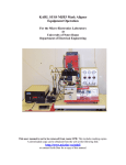
MJB3 Mask Aligner
User’s Operating Notes
Important:
This is not a comprehensive guide for use of the MJB3 Mask Aligner and not a User’s Manual
of the MJB3 Mask Aligner. This is short reminder notices and operating tips for references
only made by other users.
You can use the equipment without supervision if you are a Qualified Operator only.
Training is required before using the MJB3 Mask Aligner. To obtain training, check in the
equipment booking calendar when the machine is going to be used and make arrangements
with someone of qualified operator to observe and practice operating the machine under direct
supervision. Attend several sessions carried out by qualified operators to become familiar with
machine layout, location and operation of handles, knobs, switches, valves, etc.
Request the clean room manager for final training and test session.
No one is allowed to use the equipment without direct supervision until after final check out.
___________________________________________________________________________
The mercury lamp requires a ‘warm up’ of 20 min and should be left on all day. If the mercury
lamp is turned off it must be left to cool down for 20 min, then turned on and warmed up for a
further 20 min.
If you are using the vacuum on another machine e.g. the spinner or the old mask aligner
(SLEE) ensure that there is no mask in the MJB3 before switching the vacuum off.
___________________________________________________________________________
Microscope
light power
source
Figure 1 Overview of the MJB3 Mask Aligner
The valve on compressed air supply line has to be open before work with the mask aligner can
begin.
Compressed
Air Valve
Location of Compressed
Air Valves
MJB3 Valve (marked MGB3)
in ‘Closed’ position
Valve in ‘Open’ position
Turn on the mercury lamp. Green indicator light on the power supply (see figure 2) has to be on
when the lamp is turned ‘on’. If the green light is not on in 20 sec, switch off the power supply,
wait 20 sec, and switch on the power supply again. Allow to warm the lamp for 20 min
Figure 2 Mercury lamp power source
Switch on the vacuum pump at the wall behind the old mask aligner (SLEE)
Switch on the pressure regulator box (see figure 3 below). All 3 gauges have to show the
pressure marked by black marker notches.
Figure 3. Pressure regulator box (move up to switch on)
Switch on microscope ‘light intensity’, top white box (see figure 1 above).
Turn on the mask aligner by switching on the “Power” switch.
Ensure that the “Separation” slider is fully back (away from you) and the “Contact” arm is in “no
contact” position pointing toward you (see figure 5 below).
Separation distance
setting
contact
No contact
To separate
Contact arm is in “no
contact” position.
Separation slider is fully
back, away from you (no
separation)
Figure 4. Contact Arm and Separation Lever
Move the microscope to central position, the ‘rod’ to the left of the optics is used for this purpose
– make sure to depress button on rod otherwise it will not function.
Figure 5.
Place your mask ‘Glass’ side down on the mask holder, when in place flick the ‘Mask’ switch on
the MJB3 unit. Check to make sure that the vacuum is working, you shouldn’t be able to move
your mask.
Figure 6. Mask Holder
Figure 7. Mask Aligner Buttons
Loosen the bracket that fixes mask into place, then slide the mask holder into position. Do not
tight the screws and do not fix the mask!
The chuck
Sample
tray
Transport
vacuum
button
Sample
tray edge
White bar
edge
Figure 8.
Rotate the sample tray until it has its edge parallel to the white bar.
Align the sample tray in the middle
position in x directions: there should be
no gap between the sample tray edge
and the white bar edge.
Align the sample tray in the middle
position in y directions: set the tray to
have gap A equal to the gap B
Figure 9.
A
B
Place sample in the centre of the chuck, covering the vacuum ring.
Whilst pressing the ‘Transport vacuum button’(silver button located far right of table) then slide
sample in fully beneath the mask, once in position release the button.
Theta
Adjustment
X - Adjustment
Y - Adjustment
Z – Adjustment Lock
Z - Adjustment
Figure 10.
Slowly rotate the contact arm to the contact position (Fig. 4) to move the chuck with your
sample up to the mask (see Fig. 11). As far as the mask is not fixed, the sample will move it up
and you will able to see this looking at the mask holder corner (Fig. 11C).
1
2
3
4
8
5
9
B
Figure 11. (A) Drawing and (B) scheme (not in scale) of sample stage and mask holder
1 Mask holder
2 Mask
3 Wafer
4 Chuck
5 Chuck stage
6 Spindle
7 Precise ball-bearing guide 8 Pneumatic brake
9 Levelling pistons
C
mask holder is not fixed
and is lifted up
D
mask holder is fixed
chuck tilts to compensate a wedge
E
F
levelling pistons are fixed with pneumatic
brake
levelling pistons are fixed with pneumatic
brake
contact arm is in “contact” position
contact arm is in “contact” position
“contact” light is on
“contact” light is on
separation lever is in “separation” position
Figure 11
Unlock the Z-adjustment knob (Fig. 12) and adjust the height of the stage to have the photo
mask holder moving up for ~0.5 mm when the contact arm is in contact position.
Leave the contact arm in “no contact” position
Lock the Z-adjustment knob.
Tighten the bracket that fixes mask into place.
Now, slowly rotate the contact arm to the “contact” position (Fig. 4) again to move the chuck
with your sample up to the mask. As far as the mask is fixed now, the sample will levelled with
the mask and the wedge between the mask and your sample will be compensated (Fig. 11D).
When the contact arm is completely moved outwards in “contact” position, the “contact” light is
on and levelling pistons are fixed with pneumatic brake (Fig. 11E).
Fig. 12. Z-knob locking switch. Left - Z-knob is unlocked. Left - Z-knob is locked
Move the separation lever is in “separation” position. The levelling pistons remain fixed with
pneumatic brake. The contact arm remains in “contact” position. The “contact” light remains on.
The chuck is moving down for the distance which can be regulated by the slider (Fig. 4). The
wafer surface remains to be parallel to the mask.
Now, you can perform fine alignment using the x, y and rotation micrometers.
When aligned, move the separation lever back in “no separation” position.
Set the exposure time. Remember that you will need to test how long your exposure needs to
be. The good starting point is 12 sec for 1.4um of AZ-5214E.
Exposure
Button
Exposure Modes
There are two modes of exposure in the MJB3 Mask Aligner:
Soft contact: in this mode, the vacuum between the chuck and the wafer is on, thus an air gap
is left between the wafer and the mask. This mode is selected by pressing the ‘soft kontakt’
button. This mode is indicated by the light in ‘soft kontakt’ button on. Advantage: less photo
resist damages, less photo mask contamination. Disadvantage: lower resolution. In its soft
contact exposure mode the MJB3 can achieve a resolution of 2.0 µm. The final data mainly
depends on process specifications such as spectral range, the distance between mask and
wafer, a function of wafer topography, cleanliness and exposure mode, as well as diffraction
reduction.
Hard contact: in this mode, the vacuum between the chuck and the wafer is off and the gap
between mask and wafer is further reduced by purging nitrogen underneath the wafer. Thus the
wafer is pushed harder against the mask and achieves a resolution in the 1 micron range. This
mode is selected by pressing the ‘soft kontakt’ button. This mode is indicated by the light in
‘soft kontakt’ button off. Advantage: higher resolution. Disadvantage: more contamination of
the mask, may lead to photo resist damage.
Hit the green Exposure button.
Stand back as the microscope body will slide forward, and the UV source shutter will open to
expose your sample, it will subsequently return to its original position.
Lower you sample away from the mask by rotating the contact arm to the ‘no contact’ position.
Slide sample tray out from beneath the mask.
The procedure is now completed, simply remove your sample. If you wish to expose another
sample, insert it into the aligner. If not follow these instructions in reverse to turn the machine
off. Do not switch of the mercury lamp.