1
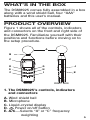
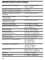
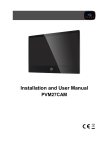
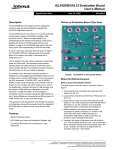
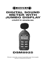
DIGITAL SOUND
METER WITH
JUMBO DISPLAY
USER’S MANUAL
DSM8925
Please read this manual carefully and thoroughly
before using this product.
TABLE OF CONTENTS
Introduction . . . . . . . . . . . . . . . . . . . . . . 3
Key Features . . . . . . . . . . . . . . . . . . . . . 4
What’s in the Box . . . . . . . . . . . . . . . . . 5
Product Overview . . . . . . . . . . . . . . 5 – 7
Setup Instructions . . . . . . . . . . . . . . . . . 8
Install Batteries . . . . . . . . . . . . . . . . 8
Operating Instructions . . . . . . . . . 8 – 15
Making Basic Measurements . . 8 – 9
Autoranging vs.
Manual Ranging . . . . . . . . . . . 9 – 11
Time and Frequency
Weighting Options . . . . . . . . . 11 – 12
Storing and Recalling
MIN and MAX Readings . . . . 12 – 13
Operating in
MAX HOLD mode . . . . . . . . . . 13 – 14
Disabling Auto Power Off . . . . . . . 14
Calibrating the Meter . . . . . . . . . . 15
Specifications . . . . . . . . . . . . . . . . . . . 16
Maintenance Tips . . . . . . . . . . . . . . . . 17
Warranty Information . . . . . . . . . .17 – 18
Return for Repair Policy . . . . . . . . . . . 18
2
INTRODUCTION
Thank you for purchasing General Tools &
Instruments’ DSM8925 Digital Sound Meter
with Jumbo Display. Please read this user’s
manual carefully and thoroughly before using
the instrument.
The DSM8925 uses an integrated condenser
microphone to measure the noise level of an
environment or the loudness of a machine,
typically in order to comply with health and/or
safety rules. The meter has a range of 30 to
130 dB and an accuracy of ±2 dB. Real-time
measurements are shown within a backlit
liquid-crystal display window in two forms: as
a three- or four-digit number, and as a line on
an analog bar graph.
Several features improve the meter’s
versatility. Among them are two userselectable operating modes: “A” or “C”
frequency weighting, and fast or slow time
response. Users also can override autoranging
(the default mode) and manually select a fixed
measurement range, improving the meter’s
response time and measurement resolution.
The meter can display the minimum and
maximum sound levels measured during a
recording session, as well as hold a maximum
level on-screen until it is exceeded.
3
Physical features of the DSM8925 include an
analog output jack for connecting to a data
logger or chart recorder, a tripod mounting
socket, and an adjustment screw for
calibrating the meter to a standard 94 dB
input.
The DSM8925 includes a wind shield ball
and is powered by four “AAA” batteries
(also included).
KEY FEATURES
• Measures sound level of a machine
or an environment
• Jumbo LCD is easy to read
• “A” or “C” frequency weighting
• Fast or slow time weighting
• Autoranging or manual ranging
• Displays maximum and minimum readings
• Max reading can be held until exceeded
• Auto power off
• Analog output for data logging
• Calibrates to standard 94dB signal
• Tripod mount socket on back
• Includes wind shield ball
• Powered by four “AAA” batteries
4
WHAT’S IN THE BOX
The DSM8925 comes fully assembled in a box
along with a wind shield ball, four “AAA”
batteries and this user’s manual.
PRODUCT OVERVIEW
Figure 1 shows all of the controls, indicators
and connectors on the front and right side of
the DSM8925. Familiarize yourself with their
positions and functions before moving on to
the setup procedure.
A
B
C
J
G
H
I
D
E
F
FRONT
K
RIGHT SIDE
1. The DSM8925’s controls, indicators
and connectors
A. Wind shield ball
B. Microphone
C. Liquid-crystal display
D. Power on/off button
E. A/C—Selects “A” or “C” frequency
weighting
5
F. REC—Enters/exits Recording mode
G. RNG—Selects autoranging or manual
ranging
H. F/S—Selects fast or slow time response
I. MAX HOLD button
J. Calibration adjustment screw
K. Analog output jack
Figure 2 shows all text and icons that could
appear in the display window at various times.
2. All possible display indications and their
meanings
REC Meter is in Recording mode, tracking
maximum and minimum sound level
measurements
MAX Digital readout is highest level
recorded since entering Recording
mode
MIN Digital readout is lowest level
recorded since entering Recording
mode
MAX HOLD Meter is in Max Hold mode. Digital
readout is highest level measured
since entering this mode
6
FAST Meter is applying fast time weighting
to inputs
SLOW Meter is applying slow time weighting
to inputs
AUTO Meter is automatically choosing
measurement range with best
resolution
MANU Meter is using user-selected
measurement range
BA Reserved for future use
SPL Abbreviation of sound pressure level
(the parameter measured)
Meter’s battery is very low on charge
and should be replaced
A Meter is applying “A” frequency
weighting to inputs
C Meter is applying “C” frequency
weighting to inputs
dB Sound level unit (accompanies
reading at its left)
40 Range Baseline (low end of current
measurement range, in dB). “40”
indicates 40 to 70 dB range; other
possible numbers in this display
position are 60 (for 60 to 90 dB
range), 80 (for 80 to 110 dB range)
and 100 (for 100 to 130 dB range)
+0, +10, Labels of analog bar graph scale.
+20, +30 Indicate amplitude of input (in dB)
relative to Range Baseline above left
end of graph
7
SETUP INSTRUCTIONS
INSTALL FOUR BATTERIES
The meter’s battery compartment is
accessible from the back of the unit. Use a
Philips-head screwdriver to remove the one
screw holding the cover in place. Then install
the four included “AAA” batteries so their +
and – ends match the images stenciled inside
the compartment. Finally, replace the cover
and secure it with the Philips-head screw.
OPERATING
INSTRUCTIONS
MAKING BASIC MEASUREMENTS
To begin, press the button to power on the
meter. The display will take a few seconds to
stabilize and then begin reading out real-time
sound level measurements.
Note how the digital numbers and the
readings from the analog bar graph track each
other. At times, the two displays may seem
slightly out of sync—and they are, because
they refresh at different rates.
Also note how the number above the left end
of the bar graph—the Range Baseline—
changes each time a much louder or softer
sound is heard. Each change confirms that the
meter is operating in Autoranging mode. To
demonstrate that autoranging is on in a quiet
environment, rub the windscreen with your
hand (to simulate a loud noise) and watch the
Range Baseline change to 100.
8
To measure the loudness of a sound
source, point the microphone at it.
The meter’s default settings are autoranging
on (enabling measurements from 30 to 130
dB), fast time weighting and “A” frequency
weighting. When the meter is powered on,
AUTO will appear on the left side of the
display, with FAST on the top line and A on
the right side. Following are procedures for
changing each of these settings to suit the
application.
AUTORANGING VS.
MANUAL RANGING
The DSM8925 has four measurement ranges:
40 to 70 dB, 60 to 90 dB, 80 to 110 dB, and
100 to 130 dB. When the meter is powered
on, it automatically enters Autoranging mode.
In this mode, it automatically switches to the
range that displays the input with the finest
resolution. For example, the meter could
display a sound level of 65 dB using either the
40 to 70 dB or the 60 to 90 dB range. In
autoranging mode, it would choose the lower
of the two ranges (40 to 70 dB) because on
this scale 65 dB has a better (finer)
measurement resolution.
If you already know the loudness range of the
machine or environment you wish to measure,
and that range is limited, consider exiting
autoranging mode and operating the meter in
only one of those four fixed ranges. The
benefit of operating the meter in this mode—
called Manual Ranging mode—is speed.
9
The meter can display its results more quickly
because it does not have to first determine
which range to use.
To exit Autoranging Mode and enter
Manual Ranging mode, briefly press the RNG
button on the front panel. Note that when you
press the button, the text MANU replaces
AUTO on the left side of the display. Also note
that the Range Baseline above the left end of
the bar graph no longer changes in response
to louder or softer sounds, as in did in
Autoranging mode.
When the RNG button is pressed, the meter
randomly chooses one of the four ranges.
Accordingly, the first Range Baseline number
displayed could be 40, 60, 80 or 100. For the
highest display resolution, the low end of the
range you choose should be just below the
quietest sound you expect to hear. For
example, if your target normally produces
sound levels between 85 and 105 dB, you
should manually choose the 80 to 110 dB
range.
To manually select a specific measurement
range, briefly press the RNG button as many
times as necessary until its Range Baseline
number appears above the left end of the
analog bar graph. Each press of the RNG
button advances the Range Baseline number
by 20 dB; after 100, it returns to 40.
Note that in Manual Ranging mode, whenever
a sound level is outside the chosen range the
10
digital display will show the letters LO or HI.
If this happens often, consider switching back
to Autoranging mode.
To exit Manual Ranging mode and return to
Autoranging Mode, press and hold the RNG
button until the text AUTO replaces MANU on
the left side of the display.
TIME AND FREQUENCY
WEIGHTING OPTIONS
You can choose Fast or Slow response time
and “A” or “C” frequency weighting to suit
different applications.
By default, when the meter is powered on it
begins operating with fast time weighting
(a fast integration time constant) and “A”
frequency weighting. Fast time weighting,
with a response time of 200 milliseconds,
simulates the response time of the human ear
and is better for measuring the volume of
singular events. Slow weighting, with a
response time of 500 ms, is a better choice
for measuring the average sound level that an
ongoing process (such as machine vibration)
produces over time.
To switch the meter’s response time from
fast to slow, press the F/S button. The word
on the right side of top line of the display will
change from FAST to SLOW. To return to fast
time weighting, press the F/S button again.
As mentioned earlier, when the DSM8925 is
powered on it begins operating with “A”
frequency weighting. The shape of the “A”
11
curve simulates the response of the human
ear, and is therefore the better choice for
measuring the sound level of an environment
for the purpose of regulatory compliance,
workplace design or noise-pollution control.
By comparison, the “C” weighting curve is
flatter, and is therefore better for measuring
the sound level of a piece of machinery. In the
U.S., most OSHA-mandated sound level
measurements are made by instruments set
for slow response and “A” frequency
weighting.
To switch from “A” frequency weighting to
“C” weighting, press the A/C button. The
letter at the right of the display will change
from A to C. To switch back to “A” frequency
weighting, press the A/C button again.
STORING AND RECALLING
MIN AND MAX READINGS
The DSM8925 can also operate in
“Recording” mode, for the purpose of tracking
and displaying minimum and maximum sound
level measurements.
To enter Recording mode, press the REC
button briefly. The text REC will appear at the
upper left of the display.
To display the minimum sound level
measured since entering Recording mode,
press the REC button briefly again. The text
MIN will appear on the top line of the display
and the digital display will indicate the lowest
sound volume measured during this recording
12
session. While the digital display is showing
the minimum sound value, the meter
continues to measure real-time sound level
inputs and to display its results on the analog
bar graph.
To display the maximum sound level
measured since entering Recording mode,
press the REC button briefly one more time.
The text MAX will replace MIN on the top line
of the display and the digital display will
indicate the highest sound volume measured
during this recording session. While the digital
display is showing the maximum sound value,
the meter continues to measure real-time
sound level inputs and to display its results on
the analog bar graph.
To repeat the process, press and hold the
REC button briefly. This does not begin a new
recording session. It simply extends the
duration of the current session.
To exit Recording mode, press and hold the
REC button until the text REC disappears from
the top line of the display.
OPERATING IN MAX HOLD MODE
You may want to use the meter’s digital
display to show the loudest sound level
measured up to a certain point in time. In this
operating mode—called MAX HOLD mode—
the digital display shows and holds the
loudest sound level received since entering
that mode. The analog bar graph continues to
display measured input levels in real time.
13
However, the digital display is updated only
when the meter detects a louder sound.
To enter MAX HOLD mode, press the MAX
HOLD button at the lower right of the front
panel. To exit this mode, press the MAX HOLD
button again
DISABLING AUTO POWER OFF
By default, the meter powers off automatically
after 20 minutes to avoid discharging the
batteries. However, you can disable this
feature if you would like to track sound levels
over a longer period of time. For this purpose,
you will also need to feed the meter’s analog
output signal (available via a jack on the right
side of the unit) into a chart recorder or data
logger.
To disable Auto Power Off, first power off the
meter by pressing the button. Then power
on the meter in a special way by pressing the
button and pressing and holding the MAX
HOLD button at the same time. This will cause
the letter “n” to appear briefly on the digital
display. Once “n” has appeared, you can
release the MAX HOLD button.
Once Auto Power Off has been disabled, the
meter will no longer shut down automatically
after 20 minutes. It will remain on until the
button is pressed again to power off the
instrument. Once the meter is powered off,
Auto Power Off will automatically be reenabled when the meter is powered on again.
14
CALIBRATING THE METER
The DSM8925 must be calibrated before
it can make accurate sound level
measurements. To begin, obtain a standard
acoustic calibrator with a 94 dB output, such
as General Tools & Instruments’ SCAL1356.
Then enter Manual Ranging mode and choose
the 80 to 110 dB range using the steps
outlined on p. 9. Changing the response time
is unnecessary. However, make sure that “C”
weighting is chosen and that that the meter is
not operating in MAX HOLD mode.
To calibrate the meter, insert its microphone
in the hole of the acoustic calibrator. Power on
the calibrator and set its output range to the
range containing 94 dB. Using a small Philipshead screwdriver, turn the calibration
adjustment screw on the right side of the
DSM8925 until its display shows the same
reading as the calibrator’s, ±0.1 dB.
15
SPECIFICATIONS
Measurement Range
Measurement Accuracy
Digital Display Resolution
Digital Display Refresh
Period
Analog Bar Graph
Resolution
Analog Bar Graph
Refresh Period
Frequency Range
Display Window Size
Digit Height
Microphone
Diameter/Type
Battery Life
Analog Output
Operating Temperature
Storage Temperature
Dimensions
Weight
Power Source
16
40 to 130 dB over
four ranges
±2 dB
0.1 dB
160 milliseconds
1 dB
40 milliseconds
31.5 Hz to 8 kHz
1.18 (W) x 1.38 (H) in.
(30 x 35mm)
0.6 in. (15.2mm)
0.5 in. (12.7mm)
Electret condenser
60 hours (typical)
0 to 0.707Vrms
32° to 122°F
(0° to 50°C)
@<80% R.H.
-4° to 122°F
(-20° to 50°C)
@<90% R.H.
9 x 2.25 x 1.1 in.
(230 x 57 x 28mm)
4.6 oz. (130g)
4 “AAA” batteries
MAINTENANCE TIPS
When the
icon appears at the upper right
of the display, it’s time to replace the four AAA
batteries that power the instrument (although
measurements will remain valid for several
hours after the icon first appears). To replace
the batteries, follow the Setup Instructions
on p. 8.
Remove the batteries when storing the meter
for an extended period of time.
Do not drop or disassemble the meter or
immerse it in water.
WARRANTY
INFORMATION
General Tools & Instruments’ (General’s)
DSM8925 Digital Sound Level Meter with
Jumbo Display is warranted to the original
purchaser to be free from defects in material
and workmanship for a period of one year.
Subject to certain restrictions, General will
repair or replace this instrument if, after
examination, the company determines it to
be defective in material or workmanship.
This warranty does not apply to damages that
General determines to be from an attempted
repair by non-authorized personnel or misuse,
alterations, normal wear and tear, or
accidental damage. The defective unit must be
returned to General Tools & Instruments or to
a General-authorized service center, freight
prepaid and insured.
17
Acceptance of the exclusive repair and
replacement remedies described herein is a
condition of the contract for purchase of this
product. In no event shall General be liable for
any incidental, special, consequential or
punitive damages, or for any cost, attorneys’
fees, expenses, or losses alleged to be a
consequence of damage due to failure of, or
defect in any product including, but not limited
to, any claims for loss of profits.
RETURN FOR REPAIR
POLICY
Every effort has been made to provide you
with a reliable product of superior quality.
However, in the event your instrument
requires repair, please contact our Customer
Service to obtain an RGA (Return Goods
Authorization) number before forwarding the
unit via prepaid freight to the attention of our
Service Center at this address:
General Tools & Instruments
80 White Street
New York, NY 10013
212-431-6100
Remember to include a copy of your proof of
purchase, your return address, and your
phone number and/or e-mail address.
18
NOTES
________________________________
________________________________
________________________________
________________________________
________________________________
________________________________
________________________________
________________________________
________________________________
________________________________
________________________________
________________________________
________________________________
________________________________
________________________________
________________________________
________________________________
________________________________
________________________________
19
GENERAL TOOLS & INSTRUMENTS
80 White Street
New York, NY 10013-3567
PHONE (212) 431-6100
FAX (212) 431-6499
TOLL FREE (800) 697-8665
e-mail: [email protected]
www.generaltools.com
DSM8925 User’s Manual
Specifications subject to change without notice
©2011 GENERAL TOOLS & INSTRUMENTS
NOTICE - WE ARE NOT RESPONSIBLE
FOR TYPOGRAPHICAL ERRORS.
MAN#DSM8925 6/20/11