1
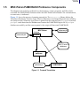
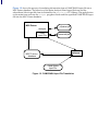
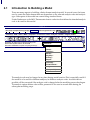
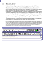
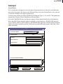
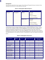
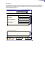
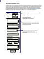
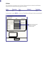
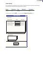
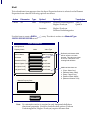
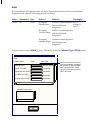
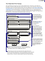
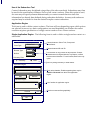
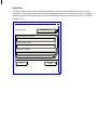
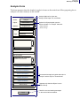
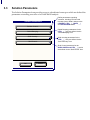
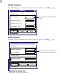
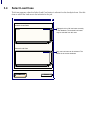
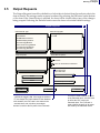
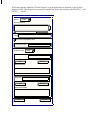
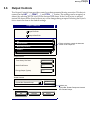
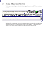
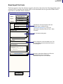
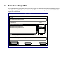
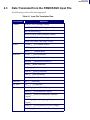
C O N T E N T S
MSC.Patran PAMCRASH Preference Guide
MSC.Patran PAMCRASH Preference Guide,
CHAPTER
1
Overview
■
Purpose, 2
■
PAMCRASH Product Information, 3
■
What is Included with this Product?, 3
■
PAMCRASH Preference Integration with MSC.Patran, 4
■
MSC.Patran PAMCRASH Preference Components, 5
■
Introduction to Building a Model, 8
■
Coordinate Frames, 12
■
Finite Elements, 13
❑ Nodes, 14
❑ Elements, 15
■
Material Library, 16
❑ Materials Form, 17
■
Element Properties, 27
❑ Element Properties Form, 28
- 0D Mass, 30
- Beam, 31
- Rod, 32
- Linear Spring, 33
- Shell, 34
- Solid, 36
■
Loads and Boundary Conditions, 37
❑ Loads & Boundary Conditions Form, 38
- Time Dependent (Time Varying), 41
- Contact Toolkit, 42
- Object Tables, 47
■
Load Cases, 55
■
Review of the Analysis Form, 58
❑ Analysis Form, 59
■
Translation Parameters, 61
2
Building A Model
3
Running an
Analysis
■
Solution Parameters, 62
❑ Solution Control, 63
❑ Global Damping, 64
❑ Solid Viscosity, 64
❑ Shell Control, 65
■
Select Load Case, 66
■
Output Requests, 67
■
Output Controls, 69
■
Select Group, 70
■
Setting PAMCRASH IDs, 71
■
Review of Read Input File Form, 74
❑ Read Input File Form, 75
■
Selection of Input File, 76
■
Data Translated from the PAMCRASH Input File, 77
■
Reject File, 79
Files
■
Files, 82
INDEX
■
MSC.Patran PAMCRASH Preference Guide, 83
4
Read Input File
5
MSC.Patran PAMCRASH Preference Guide
CHAPTER
1
Overview
■ Purpose
■ PAMCRASH Product Information
■ What is Included with this Product?
■ PAMCRASH Preference Integration with MSC.Patran
■ MSC.Patran PAMCRASH Preference Components
1.1
Purpose
MSC.Patran is an analysis software system developed and maintained by MSC.Software
Corporation. The core of the system is MSC.Patran, a finite element analysis pre- and postprocessor. The MSC.Patran system also includes several optional products such as advanced
postprocessing programs, tightly coupled solvers, and interfaces to third party solvers. This
document describes one of these interfaces.
The MSC.Patran PAMCRASH Application Preference provides a communication link between
MSC.Patran and PAMCRASH. It also provides customization of certain features that can be
activated by selecting PAMCRASH as the analysis code “Preference” in MSC.Patran.
The PAMCRASH Preference is fully integrated into MSC.Patran. The casual user will never need
to be aware separate programs are being used. For the expert user, there are two main
components of the preference: a PCL function, load_pamcrash(), which will load all
PAMCRASH specific definitions, like element types and material models, into the currently
opened database, and the pat3pam program used to convert model data from the MSC.Patran
database into the analysis code input file, and to translate model topology from the analysis code
input file into the MSC.Patran database.
Selecting PAMCRASH as the analysis code under the “Analysis Preference” menu modifies
MSC.Patran forms in five main areas:
1. Materials
2. Element Properties
3. Finite Elements/MPCs and Meshing
4. Loads and Boundary Conditions
5. Analysis forms
The PCL function load_pamcrash() can be invoked by simply typing its name into the
MSC.Patran command line. This will load PAMCRASH specific definitions into the MSC.Patran
database currently opened. PAMCRASH specific definitions can be added to any MSC.Patran
database (which does not already contain PAMCRASH specific definitions) at any time.
Obviously, a MSC.Patran database must be open for load_pamcrash() to operate correctly. See
PAMCRASH Preference Integration with MSC.Patran (p. 4) for complete information and a
description of how to create a new template database.
program translates model data between the MSC.Patran database and the analysis
code-specific input file format. This translation must have direct access to the originating
MSC.Patran database when PAMCRASH input file is being created.
The pat3pam
The pat3pam program also translates model topology data from the analysis, code-specific
input file into the MSC.Patran database. When reading an existing PAMCRASH input file the
MSC.Patran database must be initially empty.
Reading PAMCRASH Input Files. This release of the MSC.Patran PAMCRASH Preference
provides support for reading PAMCRASH input files. Nodes, elements, materials, LBCs,
Property Sets, and coordinate systems from keyword based input files only are supported.
Post Processing PAMCRASH Results. No Postprocessing of PAMCRASH analysis results is
currently available in MSC.Patran. It is recommended to use PAMCRASH postprocessor
PAMVIEW for this purpose.
CHAPTER 1
Overview
1.2
PAMCRASH Product Information
PAMCRASH is a general purpose explicit finite element computer program for nonlinear
dynamic analysis of structures in three dimensions. PAMCRASH is integrated into the
PAMSOLID library of solvers.
The program is developed, supported and maintained by Pam System International, ESI Group
Software Product Company, 20, Rue Saarinen, Silic 303, 94588 Rungis Cedex. 33 (1) 49 78 2800.
See the PAMCRASH/PAMSAFE User’s Manual for a general description of the software’s
capabilities.
1.3
What is Included with this Product?
The MSC.Patran PAMCRASH Preference product includes the following items:
1. A PCL function contained in p3patran.plb which will add PAMCRASH specific
definitions to any MSC.Patran database (not already containing such definitions) at
any time.
2. A PCL library called pamcrash.plb and contained in the <installation_directory>
directory. This library is used by the analysis forms to produce analysis code specific
translation parameter, solution parameter, etc. forms.
3. An executable program called pat3pam contained in the
<installation_directory>/bin/exe directory. This program translates information from
PAMCRASH input files into an MSC.Patran database and translate information from
an MSC.Patran database into a PAMCRASH input file. The program can be run
independently of MSC.Patran but is typically run underneath MSC.Patran, transparent
to the user.
4. This MSC.Patran PAMCRASH Preference Guide is included as part of the product. An
online version is also provided to allow direct access to this information from within
MSC.Patran.
3
1.4
PAMCRASH Preference Integration with MSC.Patran
Creation of a PAMCRASH Template Database. Two versions of the MSC.Patran database
are delivered with MSC.Patran. Both occur in the <installation_directory> directory and they are
named base.db and template.db. The base.db database is a MSC.Patran database into which no
analysis code specific definitions, such as element types and material models, have been stored.
The template.db database is a version of the MSC.Patran database which contains analysis code
specific definition needed by a number of the MSC supplied interfaces. In order to create a
template database which contains only PAMCRASH specific definitions, the user should follow
these steps:
1. Within MSC.Patran open a new database using base.db as the template.
2. Enter load_pamcrash() into the command line.
3. Save this database under a name like pamcrash.db to be your new “PAMCRASH only”
template database.
4. From then on, when opening a new database, choose pamcrash.db as your template
database.
Any databases derived from base.db may not contain the needed PAMCRASH specific
definitions needed to run the PAMCRASH Preference. But, PAMCRASH specific definitions can
be added to any database at any time by simply typing load_pamcrash() into the MSC.Patran
command line while the target database is the database currently opened by MSC.Patran. Due
to the savings in size and for the sake of simplicity it is highly recommended template.db not be
used as a template database and that the user create their own unique template database which
contains only the analysis code specific definitions pertaining to the analysis codes of immediate
interest. For more details about adding analysis code specific definitions to a database and/or
creating unique template databases, refer to Modifying the Database Using PCL (p. 347) in the
PCL and Customization or to the MSC.Patran Installation and Operations Guide.
CHAPTER 1
Overview
1.5
MSC.Patran PAMCRASH Preference Components
The diagrams shown below indicate how the functions, scripts, programs, and files which
constitute the PAMCRASH Preference affect the MSC.Patran environment. Site customization,
in some cases, is indicated.
Figure 1-1 shows the process of running an analysis. The pamcrash.plb library defines the
Translation Parameter, Solution Type, Solution Parameter, and Output Request forms called by
the Analysis form. When the Apply button is pushed on the Analysis form pat3pam is executed.
pat3pam reads data from the database and creates the PAMCRASH input file. If pat3pam
finishes successfully, and the user requests it, the script will then start PAMCRASH.
MSC.Patran
Analysis
pamcrash.plb
p3patran.plb
Analyze
MSC. P at ra n
database
pat3pam
jobname.pc
PAMCRASH
Figure 1-1 Forward Translation
5
Figure 1-2 shows the process of translating information from a PAMCRASH input file into a
MSC.Patran database. The behavior of the main Analysis/Read input file form and the
subordinate Select input file form is dictated by the pamcrash.plb PCL library. The apply button
on the main form activates the pat3pam program which reads the specified PAMCRASH input
file into the MSC.Patran database.
MSC.Patran
p3patran.plb
Analysis
Read
Input File
pamcrash.plb
pat3pam
MSC. Pa t ra n
database
PAMCRASH
Input File
Figure 1-2 PAMCRASH Input File Translation
MSC.Patran PAMCRASH Preference Guide
CHAPTER
2
Building A Model
■ Introduction to Building a Model
■ Coordinate Frames
■ Finite Elements
■ Material Library
■ Element Properties
■ Loads and Boundary Conditions
■ Load Cases
2.1
Introduction to Building a Model
There are many aspects to building a finite element analysis model. In several cases, the forms
used to create the finite element data are dependent on the selected analysis code and analysis
type. Other parts of the model are created using standard forms.
Under Preferences on the MSC.Patran main form is a selection that defines the intended analysis
code to be used for this model.
MSC.Patran
File Group Viewport Viewing Display Preferences Tools Insight Control Help
© Geometry © FEM © LBCs© Matls© Properties © Load Cases©Fields © Analysis © Results © Insight © XYPlot
$# Session file patran.ses.01 started recording at 25
$# Recorded by MSC.Patran 03:36:58 PM
$# FLEXlm Initialization complete. Acquiring license(s)...
hp, 2
Preferences
Analysis...
Global...
Graphics...
Mouse...
Key Map...
Picking...
Report...
Geometry...
Finite Element...
Insight...
Hide Icon Help
Main Form...
The analysis code may be changed at any time during model creation.This is especially useful if
the model is to be used for different analyses, in different analysis codes. As much data as
possible will be converted if the analysis code is changed after the modeling process has begun.
The analysis option defines what will be presented to the user in several areas during the
subsequent modeling steps.
CHAPTER 2
Building A Model
These areas include the material and element libraries, including multi-point constraints, the
applicable loads and boundary conditions, and the analysis forms. The selected Analysis Type
may also affect the allowable selections in these same areas. For more details, see The Analysis
Form (p. 8) in the MSC.Patran Reference Manual, Part 5: Analysis Application.
Analysis Preference
To use the MSC.Patran PAMCRASH Analysis
Preference. This should be set to PAMCRASH.
Analysis Code:
PAMCRASH
Analysis Type:
Structural
The only Analysis Type for PAMCRASH is
Structural.
Input File Suffix:
.pc
Indicates the file suffixes used in creating file
names for PAMCRASH input and output files.
Output File Suffix:
OK
Table 2-1 summarizes the various PAMCRASH commands supported by the MSC.Patran
PAMCRASH Preference.
Table 2-1 Supported PAMCRASH Entities
File Section
CONTROL
Keyword
Method
FREE (Free Format)
NOLIST/LIST (Listing Control)
Analysis/Output Controls
NOPRINT/PRINT (Printing Control)
Analysis/Output Controls
MNTR (Monitoring)
Analysis/Output Controls
FILE (File Name)
Analysis
CPULIMIT (CPU Limit)
Analysis/Solution
Parameters/Solution Control
SHELLCHECK (Shell Geometry Limits)
Analysis/Solution
Parameters/Shell Control
DATACHECK (Data Checking)
Analysis/Solution
Parameters/Solution Control
TIMESTEP (Shell Time Step Control)
Analysis/Solution
Parameters/Shell Control
TITLE_/_ (Job Title)
Analysis
INCLU_/_ (Include File)
Analysis/Translation Control
CTRL__/_
Analysis/
9
Table 2-1 Supported PAMCRASH Entities (continued)
File Section
MATERIAL
Keyword
Method
SOLID TYPE 1 (Elastic Plastic, bilinear
and stress/strain)
Materials/Properties (3D)
SOLID TYPE 2 (Crushable Foam)
Materials/Properties (3D)
SOLID TYPE 5 (Viscoelastic)
Materials/Properties (3D)
SOLID TYPE 99 (Null)
Materials/Properties(3D)
SHELL TYPE 100 (Null)
Materials/Properties(2D)
SHELL TYPE 101 (Elastic)
Materials/Properties(2D)
SHELL TYPE 102/103 (Elastic Plastic)
Materials/Properties(2D)
SHELL TYPE 105/106 (Elastic Plastic
with damage)
Materials/Properties(2D)
SHELL TYPE 130 (composite)
Materials/Properties(2D)
BEAM/BAR TYPE 200 (Null)
Materials/Properties (1D)
BEAM/BAR TYPE 201 (Elastic)
Materials/Properties (1D)
BEAM/BAR TYPE 202 (Elastic Plastic)
Materials/Properties (1D)
BAR/DASHPOT TYPE 204 (Nonlinear)*
Materials/Properties (1D)
BEAM TYPE 212 (Elastic Plastic)
Materials/Properties (1D)
PLY DATA
PLY_ _ _/ _(Composite)
Materials/Properties(2D)
NODES
FRAME_/_ (Coordinate Frame)
Geometry
NODE__/_ (Nodal Point Data)
Finite Elements
MASS__/_ (Added Mass)
Properties (0D)
BOUNC_/_ (Displacement Boundary
Condition)
LBC’s
INVEL_/_ (Initial Velocity)
LBC’s
VELBC_/_ (Velocity Boundary
Condition)
LBC’s
CONLO_/_ (Concentrated Loads &
Follower Forces)*
LBC’s
DAMP__/_ (Nodal Damping by Group)
LBC’s
SOLID_/_ (Solid Elements)
Finite Elements
SHELL_/_ (Shell Elements)
Finite Elements
BEAM__/_ (Beam Elements)
Finite Elements
BAR___/_ (Bar Elements)
Finite Elements
SPRING/_ (Spring Elements)
Finite Elements
ELEMENTS
CHAPTER 2
Building A Model
Table 2-1 Supported PAMCRASH Entities (continued)
File Section
CONSTRAINT
Keyword
Method
RIGWA_/_ (Rigid Walls)
LBC’s
NODCO_/_ (Nodal Constraints)
LBC’s
RIGBO_/_ Rigid Body (Regular only)
LBC’s
SLINT2_/_ (Sliding Interfaces)
LBC’s
AUXILIARY
FUNCT_/_ (Function)
LBC’s
PLOT
OUTPUT
THLNO_/_ (Nodal Time History)
Analysis/Output Requests
THLOC_/_ (Local Coordinate System)
Analysis/Output Requests
THLSO_/_ (Solid Element Output)
Analysis/Output Requests
THLSH_/_ (Shell and Membrane
Element Output)
Analysis/Output Requests
THLBM_/_ (Beam, Bar, Spring/Dashpot
etc. Output)
Analysis/Output Requests
TRAFO_/_(Cross sections for Force
output)
Analysis/Output Requests
SECFO_/_(Cross sections for Force
output)
Analysis/Output Requests
* Note that Non-Linear Springs and Follower Forces are not supported in this version of the
MSC.Patran PAMCRASH Preference.
1
2.2
Coordinate Frames
Coordinate frames will generate unique FRAME_/_ entries.
MSC.Patran
File Group Viewport Viewing Display Preferences Tools Insight Control Help
© Geometry © FEM © LBCs© Matls© Properties © Load Cases©Fields © Analysis © Results © Insight © XYPlot
$# Session file patran.ses.01 started recording at 25
$# Recorded by MSC.Patran 03:36:58 PM
$# FLEXlm Initialization complete. Acquiring license(s)...
hp, 2
Only Coordinate Frames which are referenced by nodes, element properties, or loads and
boundary conditions can be translated. Note that Coordinate Frames used to define skewed
boundary conditions in MSC.Patran will be translated even though they are not required in
PAMCRASH. For more information on creating coordinate frames see Creating Coordinate
Frames (p. 350) in the MSC.Patran Reference Manual, Part 2: Geometry Modeling.
CHAPTER 2
Building A Model
2.3
Finite Elements
Finite Elements in MSC.Patran allows the definition of basic finite element construction. Created
under Finite Elements are the nodes and element topology.
MSC.Patran
File Group Viewport Viewing Display Preferences Tools Insight Control Help
© Geometry © FEM © LBCs© Matls© Properties © Load Cases©Fields © Analysis © Results © Insight © XYPlot
$# Session file patran.ses.01 started recording at 25
$# Recorded by MSC.Patran 03:36:58 PM
$# FLEXlm Initialization complete. Acquiring license(s)...
hp, 2
For more information on how to create finite element meshes, see Mesh Seed and Mesh Forms
(p. 29) in the MSC.Patran Reference Manual, Part 3: Finite Element Modeling.
1
Nodes
Nodes in MSC.Patran will generate unique NODE__/_ data entries. Nodes can be created either
directly using the Node object, or indirectly using the Mesh object. Note that unconnected Nodes
may be used in a PAMCRASH model to define beam orientations and the optional centre of
gravity nodes of rigid bodies. These nodes should not be deleted.
Finite Elements
Action:
Create
Object:
Node
Method:
Edit
Node Id List
1
Analysis Coordinate Frame
Coord 0
Refer. Coordinate Frame
Coord 0
Associate with Geometry
Auto Execute
Node Location List
(0 0 0)
-Apply-
The analysis frame applies for the entire model. The
reference coordinate system is used during node
generation only.
CHAPTER 2
Building A Model
Elements
Finite Elements in MSC.Patran assigns element connectivity, such as Quad/4, for standard finite
elements. The type of PAMCRASH element to be created is not determined until the element
properties are assigned. See the Element Properties Form (p. 28) for details concerning the
PAMCRASH element types. Elements can be created either discretely using the Element object
or indirectly using the Mesh object.
Finite Elements
Action:
Create
Object:
Mesh
Type:
Surface
Output ID List
Node
1
Element
1
Elem Shape
Quad
Mesher
IsoMesh
Topology
Quad4
Elements which are not referenced by an element
property region which is understood by the
MSC.Patran PAMCRASH forward translator will not be
translated.
IsoMesh Parameters...
Node Coordinate Frames...
Surface List
Global Edge Length
Automatic Calculation
Value
0.1
-Apply-
Note: Previous versions of the MSC.Patran
PAMCRASH Preference would translate tri-elements
as degenerate quads in the analysis file “Which would
be read back into the MSC.Patran database as tris”.
This version of the preference translates tris as tris in
both directions of translation. Similarly degenerate
quads are translated as degenerate quads in both
directions of translation.
1
2.4
Material Library
The Materials form will appear when the Materials toggle, located on the MSC.Patran
application selections, is chosen. The selections made on this form will determine which
Materials form appears and, ultimately, which PAMCRASH material will be created.
Several materials within PAMCRASH differ only by the material ID, even though the material
models are identical. The difference in material ID is due to the underlying element
dimensionality. e.g. PAMCRASH Materials 1, 102 and 212 are all elastic/plastic material models
which share the same input data, however Material Type 1 is applicable only to solids, Type 102
only to shells and Type 212 only to beams. Within MSC.Patran, all of these materials are defined
as a single material model which may be applied to any of the applicable element types. When
the translator is called to produce a PAMCRASH input file, appropriate PAMCRASH material
types are created for each element type required.
The following pages give an introduction to the Materials form, and details of all the material
property definitions supported by the MSC.Patran PAMCRASH Preference.
Only material records which are referenced by an element property region or by a laminate layup will be translated. References to externally defined materials will result in special comments
in the PAMCRASH input file, with material data copied from user identified files. This allows a
user not only to insert material types that are not supported directly by the PAMCRASH
preference, but also to make use of a standard library of materials.
MSC.Patran
File Group Viewport Viewing Display Preferences Tools Insight Control Help
© Geometry © FEM © LBCs© Matls© Properties © Load Cases©Fields © Analysis © Results © Insight © XYPlot
$# Session file patran.ses.01 started recording at 25
$# Recorded by MSC.Patran 03:36:58 PM
$# FLEXlm Initialization complete. Acquiring license(s)...
hp, 2
CHAPTER 2
Building A Model
Materials Form
This form appears when Materials is selected on the main form. The Materials form is used to
provide options to create the various PAMCRASH materials.
Materials
This toggle defines the basic material orthotropy, and can
be set to Isotropic or Composite.
Create
Action:
Isotropic
Object:
Manual Input
Method:
Filter
*
The Method may be Manual Input, Materials Selector or
Externally Defined. If “Externally Defined,” this form will
have an Apply button which is used to ensure that the
named material is added to the set of available materials.
Existing Materials
Lists the created materials whose names pass
the filter.
Material Names
Defines the material name. A unique material ID will be
assigned during translation.
Description
DATE: 01-Apr-96
Time: 17:08:02
Code:
PAMCRASH
Type:
Structural
Input Properties...
Describes the material that is being created.
Indicates the active analysis code and analysis type. These
selections are made by Preferences>Analysis (p. 343) in
the MSC.Patran Reference Manual, Part 1: Basic Functions.
Generates a form that is used to define the
material properties.
Change Material Status...
Generates a form that is used to indicate the active portions
of the material model. By default, all portions of a created
material model are active.
1
Table 2-2 outlines the options when Create is the selected Action.
Table 2-2 PAMCRASH Materials
Object
Isotropic
Option 1
Option 3
❏ Linear Elastic (1/101/201)
❏ Elastoplastic
(1/102/103/105/106/202
/212)
❏ Viscoelastic (5)
❏ Null/Rigid (99/100/200)
❏ Foam (2)
Composite
Option 2
❏ Laminate
❏ Bilinear
Standard
Iterative
Isotropic Damage
Anisotropic Damage
❏ Single Curve
Standard
Iterative
Isotropic Damage
Anisotropic Damage
CHAPTER 2
Building A Model
Isotropic
Linear Elastic
This subordinate form appears when the Input Properties button is selected on the Materials
form when Isotropic is the object on the Material form, and when Linear Elastic is the selected
Constitutive Model on the Input Options form.
Use this form to define the data for PAMCRASH Material Types 1, 101 and 201. The parameters
required are: Density, Elastic Modulus and Poisson Ratio.
Note that PAMCRASH does not directly support a linear elastic material for solid elements.
When this MSC.Patran material option is applied to solid elements, a PAMCRASH material
Type 1 (Elastic/Plastic) will be written to the PAMCRASH input file, with the tangent modulus
equal to the elastic modulus, and the Yield stress set artificially high (equal to the value of the
elastic modulus).
Input Options
Constitutive Model:
Linear Elastic
Property Name
Value
Density =
Elastic Modulus =
Poisson Ratio=
Current Constitutive Models:
-Apply-
Clear
Cancel
1
Elastoplastic
The following subordinate forms appear when the Input Properties button is selected on the
Materials form when any of the options are selected.
Table 2-3 Elastoplastic Material Options
Object
Isotropic
Option 1
Elastoplastic
Option 2
Bilinear
Option 3
Standard
Iterative
Isotropic Damage
Anisotropic Damage
Single Curve
Standard
Iterative
Isotropic Damage
Anisotropic Damage
Use the forms on the next pages to define the data for PAMCRASH Material Types 1 (Solid),
102/103/105/106 (Shell), or 202/212 (Rod and Beam). Note that the strain rate dependency
model is determined at a global level, by the ISTRAT parameter. Hence the 6 strain rate
parameters cannot have names. For the sake of mapping to other codes the first two of those
parameters should be the Cowper Symonds D and p parameters. The contents of the form will
vary depending upon which option is selected. The parameters which are required are tabulated
below.
Table 2-4 Elastoplastic Parameters
Bilinear
Curve
Standard/Iterative
Iso/Anisotropic
Damage
Density
x
x
x
x
Elastic Modulus
x
x
x
x
Poisson’s Ratio
x
x
x
x
Yield Stress
x
Field
x
x
Tangent Modulus
x
x
x
1st Rate Param.
x
x
x
x
2nd Rate Param.
x
x
x
x
3rd Rate Param.
x
x
x
x
4th Rate Param.
x
x
x
x
5th Rate Param.
x
x
x
x
6th Rate Param.
x
x
x
x
Parameter
CHAPTER 2
Building A Model
Table 2-4 Elastoplastic Parameters
Parameter
Bilinear
Curve
Standard/Iterative
Iso/Anisotropic
Damage
Initial Threshold
x
Inter. Threshold
x
Inter. Damage
x
Ultim. Threshold
x
Ultim Damage
x
2
Elastoplastic
The following form is typical of Elastoplastic material Input data forms when the Bilinear
definition method is selected. Use this form to define the data for PAMCRASH Materials Types
1, 101, and 102.
The Bilinear option requires
definition of the tangent modulus.
For the “Single Curve” option the
yield stress is replaced by a field
defining effective stress vs effective
plastic strain.
Input Options
Elastoplastic
Constitutive Model:
Bilinear
Description:
Standard (1/102/212)
Implementation:
Choose between the Standard,
Iterative, Isotropic Damage and
Anisotropic Damage
implementations.
Value
Property Name
Density =
Elastic Modulus =
Note that this is a Strain Field if the
Single Curve option is selected. Note,
this translates to one curve in the
“CURVE” definition rather than using
the “Single Stress Strain” option.
Poisson Ratio =
Yield Stress =
Tangent Modulus =
1st Strain Rate Param. =
The tangent modulus is only
required for the bilinear curve type.
2nd Strain Rate Param. =
3rd Strain Rate Param. =
4th Strain Rate Param. =
These parameters are required only if
rate dependency is required. The first
two terms are the Cowper Symonds D
and p parameters if that model was
selected on the Analysis Forms.
Damage Parameters will be present
depending on the selected
implementation.
5th Strain Rate Param. =
6th Strain Rate Param. =
Current Constitutive Models:
-Apply-
Clear
Cancel
CHAPTER 2
Building A Model
Viscoelastic
This subordinate form appears when the Input Properties button is selected on the Materials
form when the Viscoelastic Constitutive model is selected. Use this form to define the data for
PAMCRASH Material Type 5.
Input Options
Constitutive Model:
Viscoelastic
Property Name
Value
Density =
Bulk Modulus =
Short-Time Shear Mod. =
Long-Time Shear Mod. =
Decay Constant =
Current Constitutive Models:
-Apply-
Clear
Cancel
2
Null Rigid
This subordinate form appears when the Input Properties button is selected on the Materials
form when the Null Rigid Constitutive model is selected. Use this form to define the data for
PAMCRASH Material Types 99, 100 and 200.
Input Options
Null Rigid
Constitutive Model:
Property Name
Value
Density =
Elastic Modulus =
Poisson Ratio =
Current Constitutive Models:
-Apply-
Clear
Cancel
CHAPTER 2
Building A Model
Foam
This subordinate form appears when the Input Properties button is selected on the Materials
form when the Foam constitutive model is selected.Use this form to define the data for
PAMCRASH Material Type 2.
Input Options
Foam
Constitutive Model:
Value
Property Name
Density =
Bulk Unloading Modulus =
Shear Modulus =
Yield function A0 =
Yield function A1 =
Yield function A2 =
Tensile Cutoff Pressure =
Note that this requires a strain
dependent field. This field can
have up to 10 pairs of datapoints.
Pressure v’s Vol.Strain =
1st Strain Rate Param. =
2nd Strain Rate Param. =
3rd Strain Rate Param. =
Additional data list:
4th Strain Rate Parameter
5th Strain Rate Parameter
Current Constitutive Models:
6th Strain Rate Parameter
-Apply-
Clear
Cancel
2
Composite
Laminate
This subordinate form appears when Composite is the object on the Material form, and laminate
is the selected method. Only PLY Model 0 (Unidirectional composite bi-phase ply model) is
supported and only the element local coordinate system is supported for specifying ply
orientation.
Laminated Composite
Stacking Sequence Convention
Offset
Total
Stacking Sequence Definition: Select an Existing Material.
Material Name
Insert Material Names
Thickness
Text Entry Mode
Orientation
Delete Selected Rows
Insert
◆ Material Names
◆
◆ Thicknesses
◆
◆ Orientations
Load Text Into Spreadsheet
Show Laminate Properties...
Clear Text and Data Boxes
CHAPTER 2
Building A Model
2.5
Element Properties
The Element Properties form appears when the Element Properties toggle, located on the
MSC.Patran main form, is chosen.There are several option menus available when creating
element properties. The selections made on the Element Properties form will determine which
element property form appears, and ultimately, which PAMCRASH element will be created.
The following pages give an introduction to the Element Properties form, and details of all the
element property definitions supported by the MSC.Patran PAMCRASH Preference.
MSC.Patran
File Group Viewport Viewing Display Preferences Tools Insight Control Help
© Geometry © FEM © LBCs© Matls© Properties © Load Cases©Fields © Analysis © Results © Insight © XYPlot
$# Session file patran.ses.01 started recording at 25
$# Recorded by MSC.Patran 03:36:58 PM
$# FLEXlm Initialization complete. Acquiring license(s)...
hp, 2
2
Element Properties Form
This form appears when Element Properties is selected on the main form. There are four option
menus on this form (under Dimension), each will determine which PAMCRASH element type
will be created, and which property forms will appear. The individual property forms are
documented later in this section. For a full description of this form, see Element Properties
Forms (p. 41) in the MSC.Patran Reference Manual, Part 5: Functional Assignments.
Element Properties
Use this option menu to define the elements dimension.
The options are:
Create
Action:
Dimension:
2D
Type:
Shell
0D (point elements)
1D (bar elements)
2D (tri and quad elements)
3D (tet, wedge, and hex elements)
Existing Property Sets
This option menu depends on the selection made in
the Dimension option menu. Use this menu to define
the general type of element.
Property Set Name
Option (s):
Uniform Underintegration
This option menu may or may not be presented,
and its contents depend heavily on the
selections made in Dimension and Type. See
for more help.
Input Properties...
Application Region
Select Members
Group Create
Remove
Add
Application Region
-Apply-
CHAPTER 2
Building A Model
The following table outlines the option menus when Analysis Type is set to Structural. Note that
not all material types are supported for all properties. This is a function of PAMCRASH.
Table 2-5 Structural Options
Degree
Type
0D
❏ 0D Mass
1D
❏ Beam
Option 1
Option 2
❏ Rod
❏ Spring
2D
❏ Shell
❏ Homogeneous
Uniform Underintegration
Hughes-Tezduyar
❏ Laminate
Uniform Underintegration
Hughes-Tezduyar
3D
❏ Solid
❏ H’glass Viscous Base
Uniform
Underintegration
❏ H’glass Viscous
Shape Selective
Reduced Integration
❏ H’glass Stiffness
Shape
2
0D Mass
This subordinate form appears when the Input Properties button is selected on the Element
Properties form when the following options are chosen.
Action
Dimension
Type
Create
0D
Mass
Option(s)
Topologies
Point
Use this form to create a MASS__/_ data entry. This defines added mass for the structural model.
Input Properties
0D/Added Mass
Property Name
Value
Value Type
Mass in X-direction
Real Scalar
Mass in Y-direction
Real Scalar
Mass in Z-direction
Real Scalar
Inertia Ixx
Real Scalar
Inertia Iyy
Real Scalar
Inertia Izz
Real Scalar
Field Definitions
OK
Defines the mass and inertia
properties in the global
coordinate system.
CHAPTER 2
Building A Model
Beam
This subordinate form appears when the Input Properties button is selected on the Element
Properties form when the following options are chosen.
Action
Dimension
Type
Create
1D
Beam
Option(s)
Topologies
Bar/2
Use this form to create a BEAM___/_ entry. The area and other data is written to a Material Type
200/201/212 record.
Input Properties
Beam
Property Name
Value
Value Type
Material Name
Mat Prop Name
Beam Orientation
Node Id
Cross Sect. Areas
Real Scalar
Inertias Is
Real Scalar
Inertias It
Real Scalar
Inertias Jr
Real Scalar
Material Property Sets
OK
Defines the material to be used. A
list of all materials, currently in the
database, is displayed when data is
entered. Either select from the list
using the mouse, or type in the
name. This property is required.
Defines the cross-sectional area of
the element. These values can either
be real values, or references to
existing field definitions. This
property is required. Use the field
definition with care as this can result
in a material record for each element.
Additional data here are:
1.
2.
3.
4.
Shear Effective Area
[Memb. Damp. Ratio]
[Bend.Damp. Ratio]
[Torsion Damp. Ratio]
3
Rod
This subordinate form appears when the Input Properties button is selected on the Element
Properties form when the following options are chosen.
Action
Dimension
Type
Create
1D
Rod
Option(s)
Topologies
Bar/2
Use this form to create a BAR___/_ entry. The area and membrane damping data is written to a
Material Type 200/201/202 record.
Input Properties
1D/Rod
Property Name
Value
Value Type
Material Name
Mat Prop Name
Cross Sect. Areas
Real Scalar
[Memb. Damp. Ratio]
Real Scalar
Defines the material to be used. A list
of all materials, currently in the
database, is displayed when data is
entered. Either select from the list
using the mouse, or type in the name.
This property is required.
Defines the cross-sectional area of
the element. These values can either
be real values, or references to
existing field definitions. This property
is required. Use the field definition
with care as this can result in a
material record for each element.
Material Property Sets
OK
CHAPTER 2
Building A Model
Linear Spring
This subordinate form appears when the Input Properties button is selected on the Element
Properties form when the following options are chosen.
Action
Dimension
Type
Create
1D
Spring
Option(s)
Topologies
Bar/2
Use this form to create a BAR___/_ and a simplified Material Type 204 entry.
Input Properties
Linear Spring
Property Name
Value
Value Type
Spring Constant
Real Scalar
[Damping Coefficient]
Real Scalar
[Initial Elongation]
Real Scalar
Field Definitions
OK
3
Shell
This subordinate form appears when the Input Properties button is selected on the Element
Properties form when the following options are chosen.
Action
Dimension
Type
Option1
Option(2)
Topologies
Create
2D
Shell
Homogeneous
Uniform Underintegration
Hughes-Tezduyar
Tria/3,
Quad/4
Laminate
Hughes-Tezduyar
Uniform Underintegration
Use this form to create a SHELL___/_ entry. The data is written to a Material Type
100/101/102/103/105/106 record.
Input Properties
Homogeneous
Property Name
Value
Value Type
Material Name
Mat Prop Name
Thickness
Real Scalar
[Quadrature Rule]
Integer
[Memb H’glass Coeff]
Real Scalar
[w-H’glass Coeff]
Real Scalar
[q-H’glass Coeff.]
Real Scalar
Defines the thickness which
will be uniform over each
element. This value can either
be real or a reference to an
existing field definition.
Additional data here are:
1.
2.
3.
4.
5.
[Trans. Shear Corr.]
[Stiffness Damp. Ratio]
[Damp. Target Freq.]
[Deletion Plastic Strain]
[Minimum Deletion Time]
Material Property Sets
OK
Note: No orientation section is required as only laminated shells have
directional properties. Note also that both shell options (Uniform
Underintegration/Hughes-Tezduyar) require the same data.
CHAPTER 2
Building A Model
Use this form to create a SHELL_ _/_ entry. The data is written to a Material Type 130 record.
Input Properties
Composite
Property Name
Value
Value Type
Material Name
Mat Prop Name
[Material Orientation]
Vector
[Stiffness Damp. Ratio]
Real Scalar
[Damp.Target Freq.]
Real Scalar
[Memb H'glass Coeff]
Real Scalar
[w-H'glass Coeff]
Real Scalar
[q-H'glass Coeff.]
Real Scalar
[Trans.Shear Corr.]
Real Scalar
Material Property Sets
OK
Additional
data here is
[Minimum
Deletion
Time.]
3
Solid
This subordinate form appears when the Input Properties button is selected on the Element
Properties form when the following options are chosen.
Action
Dimension Type
Option 1
Option 2
Create
3D
Hourglass
Viscous Base
Uniform Underintegration Tet/4,
Wedge/6
Selective Reduced
Hex/8
Integration
Hourglass
Viscous Shape
Uniform Underintegration
Solid
Topologies
Selective Reduced
Integration
Hourglass
Uniform Underintegration
Stiffness Shape
Selective Reduced
Integration
Use this form to create a SOLID_/_ entry. The data is written to a Material Type 1/2/5/99 record.
Input Properties
Solid
Property Name
Value
Value Type
Material Name
Mat Prop Name
[Quad. Visc.Mult]
Real Scalar
[Quad.Bulk Visc Coeff.]
Real Scalar
[Lin.Bulk Visc Coeff.]
Real Scalar
[H’glass Visco Coeff.]
Real Scalar
Material Property Sets
OK
Defines the material to be used.
A list of all materials, currently in
the database, is displayed when
data is entered. Either select
from the list using the mouse, or
type in the name.
CHAPTER 2
Building A Model
2.6
Loads and Boundary Conditions
The Loads and Boundary Conditions form will appear when the Loads/BCs toggle, located on
the MSC.Patran application selections, is chosen. When creating loads and boundary conditions
there are several option menus. The selections made on the Loads and Boundary Conditions
menu will determine which loads and boundary conditions form appears, and ultimately, which
PAMCRASH loads and boundary conditions will be created.
The following pages give an introduction to the Loads and Boundary Conditions form, and
details of all the loads and boundary conditions supported by the MSC.Patran PAMCRASH
Analysis Preference.
MSC.Patran
File Group Viewport Viewing Display Preferences Tools Insight Control Help
© Geometry © FEM © LBCs© Matls© Properties © Load Cases©Fields © Analysis © Results © Insight © XYPlot
$# Session file patran.ses.01 started recording at 25
$# Recorded by MSC.Patran 03:36:58 PM
$# FLEXlm Initialization complete. Acquiring license(s)...
hp, 2
3
Loads & Boundary Conditions Form
This form appears when Loads/BCs is selected on the main form. The Loads and Boundary
Conditions form is used to provide options to create the various PAMCRASH loads and
boundary conditions. For a definition of full functionality, see Loads and Boundary
Conditions Form (p. 18) in the MSC.Patran Reference Manual, Part 5: Functional Assignments.
Load/Boundary Conditions
Action:
Create
Object:
Displacement
Type:
Nodal
Structural
Analysis Type
Current Load Case:
Defines the general load type to be applied.
Object choices are Displacement, Force,
Initial Velocity, Velocity, Contact, Geometric
Rigid Wall, Planar Rigid Wall, Nodal Rigid
Body, Nodal Constraint, Nodal Damping.
Defines what type of region is to be loaded. The
available options here depends on the selected
Object. The general selections can be Nodal or
Element Uniform. Nodal is applied explicitly to
nodes. Element Uniform defines a constant
value to be applied over an entire element,
element face, or element edge.
Default...
Type:
Time Dependent
Current Load Case type is set on the Load
Case menu. When the Load Cases toggle,
located on the main form, is chosen the Load
Cases menu will appear. Under Load Case
Type, select either Static or Time Dependent,
then enter the name of the case, and click on
the apply button.
Existing Sets
New Set Name
Input Data...
Select Application Region...
-Apply-
Generates Transient Input Data form.
CHAPTER 2
Building A Model
The following table outlines the options when Create is the selected action.
Table 2-6 Loads and Boundary Condition Objects
Object
Type
❏ Displacement
Nodal
❏ Force
Nodal
❏ Initial Velocity
Nodal
❏ Velocity
Nodal
❏ Contact
Element Uniform
❏ Geometric Rigid Wall
Nodal
❏ Planar Rigid Wall
Nodal
❏ Nodal Rigid Body
Nodal
❏ Nodal Constraint
Nodal
❏ Nodal Damping
Nodal
3
Static (Not Time Varying)
This subordinate form appears when the Input Data button is selected on the Loads and
Boundary Conditions form when the Current Load Case Type is Static. The Current Load Case
Type is set on the Load Case form, for more information see Loads and Boundary Conditions
Form (p. 18) in the MSC.Patran Reference Manual, Part 5: Functional Assignments. The information
on the Input Data form will vary depending on the selected Object. Defined below is the
standard information found on this form. Note that this form is not used with the Pamcrash
Preference.
Input Data
Load/BC Set Scale Factor
Defines a general scaling factor for all values
defined on this form. The default value is 1.0.
Primarily used when field definitions are used to
define the load values.
1
Translations (T1, T2, T3)
Input Data in this section will vary. See
Object Tables (p. 47) for detailed
information.
Rotations (R1, R2, R3)
When specifying real values in the Input
Data entries, spatial fields can be
referenced. All defined spatial fields
currently in the database are listed. If the
input focus is placed in the Input Data entry,
and a spatial field is selected by double
clicking in this list, a reference to that field
will be entered in the Input Data entry.
Spatial Fields
FEM Dependent Data...
Analysis Coordinate Frame
Coord 0
OK
Reset
Displays a Discrete FEM Fields input form to
allow field creation and modification within the
loads/bcs application. Visible only when focus
is set in a databox which can have a DFEM field
reference.
Defines the coordinate frame used to interpret the
degree-of-freedom data defined on this form. This
only appears on the form for Nodal type loads.
This can be a reference to any existing coordinate
frame definition.
CHAPTER 2
Building A Model
Time Dependent (Time Varying)
This subordinate form appears when the Input Data button is selected on the Loads and
Boundary Condition form when the Current Load Case Type is Time Dependent. The Current
Load Case Type is set on the Load Case form, for more information see Loads and Boundary
Conditions Form (p. 18) in the MSC.Patran Reference Manual, Part 5: Functional Assignments and
Load Cases (p. 55). The information on the Input Data form will vary, depending on the
selected Object. However, it should be noted that not all LBC Objects support time dependence.
Defined below is the standard information found on this form.
Input Data
Load/BC Set Scale Factor
1
Spatial Dependence
* Time Dependence
Defines a general scaling
factor for all values defined on
this form.The default value is
1.0. Primarily used when field
definitions are used to define
the load values.
Translations <T1 T2 T3>
Input Data in this section will
vary. See Object Tables
(p. 47) for detailed
information.
Rotations <R1 R2 R3>
Spatial Fields
Time Dependent Fields
FEM Dependent Data...
Analysis Coordinate Frame
Coord 0
OK
Reset
When specifying time
dependent values in the Input
Data entries, time dependent
fields can be referenced. All
defined time dependent fields
currently in the database are
listed. If the input focus is
placed in the Input Data entry,
and a time dependent field is
selected by double clicking in
this list, a reference to that field
will be entered in the Input Data
entry.
Defines the coordinate frame to
be used to interpret the degreeof-freedom data defined on this
form. This only appears on the
form for Nodal type loads.
This can be a reference to any
existing coordinate frame
definition.
Displays a Discrete FEM Fields input form to allow field creation and
modification within the loads/bcs application. Visible only when focus is
set in a databox which can have a DFEM field reference.
When specifying real values in the Input Data entries, spatial fields can be
referenced. All defined spatial fields currently in the database are listed. If the input
focus is placed in the Input Data entry, and a spatial field is selected by double
clicking in this list, a reference to that field will be entered in the Input Data entry.
4
Contact Toolkit
This section describes the user interface provided by MSC.Patran to access the contact features
of explicit dynamics finite element codes. This interface is used during definition of the contact
LBC types: Self Contact, Subsurface, Master-Slave Surface, and Master-Slave Node.
Tools have been provided to enable the user to quickly and easily define contact conditions.
Specification of contact is conceptually simple, involving either one or two contact surfaces, and
a set of contact parameters which control the interaction of the surfaces.
Contact Types. A contact condition in which a single logical surface may come into contact
only with itself is described as self-contact, and requires the specification of a single Application
Region. A contact condition in which two logical surfaces may contact each other is described as
Master-Slave contact, and requires specification of two Application Regions. Master-Slave
contact is further subdivided by the definition of Master-Slave Surface and Master-Slave Node.
Master-Slave Surface describes the condition in which both the master and slave surfaces are
defined using element faces, whereas Master-Slave Node describes the condition where the
Slave surface is described only using nodes.
Contact Construction. Tools are provided to enable the construction of contact surfaces, using
the standard MSC.Patran select tool mechanisms (2D elements, 3D element faces), or groups.
Contact subsurfaces can also be constructed using these tools, and later used to define a
complete logical contact surface. This functionality allows the user to use the select tool to
specify application regions on MSC.Patran geometry or the associated FEM entities or to define
a more complex contact surface that is assembled from a mixture of 2D and 3D element faces,
and to simply combine groups of 2D elements taking into account the direction of the contact
outward normal. (For 2D elements, the outward normal can be reversed for contact purposes
without modifying the underlying element topology.) Use of the group select mechanism is
restricted to FEM entities only. Visualization of the specified contact condition is provided by
graphically previewing but is not currently supported for geometry entities.
“Simple” contact surfaces include surfaces which may be described entirely by the faces of 3D
elements, or by 2D elements whose outward normals are aligned with the desired contact
normal direction. These contact surfaces may be constructed entirely using a single select
mechanism (either Select Tool or Group method). Simple contact surfaces may not include a
mixture of 3D element faces and 2D elements, or 2D elements whose outward normals are not
all aligned with the desired contact normal direction.
“Complex” contact surfaces are defined as those surfaces which consist of a mixture of 2D
elements and 3D element faces, or all 2D elements but with some of the outward normals
incorrectly aligned. Contact conditions which include complex contact surfaces must be
constructed using “Subsurfaces,” where each subsurface is a “Simple” contact surface.
Definition of contact surfaces is limited to one method, i.e. it is not permissible to mix “Select
Tool,” “Group,” or “Subsurface” within the definition of a contact surface.
Use of the Select Tool. The select tool is used to graphically select the desired entities from the
model. When this method is selected, the user must specify which dimensionality the intended
object has, i.e. 3D, 2D or Nodal. If the selected dimensionality is 2D, then the user can further
specify whether the top, bottom or both surfaces option is required. Selection of top will result
in a contact surface whose outward normal is coincident with the element outward normal,
whereas selection of bottom will result in a contact surface whose outward normal is in the
opposite direction to the element outward normal. The user can toggle between Top, Bottom or
Both at any time during selection; however, all of the selected entities will be assigned the same
logical direction. Selection of 3D allows the user to select either all or all free faces of 3D elements.
CHAPTER 2
Building A Model
No user specification of the contact normal direction is required for 3D elements since the
program automatically specifies this direction. No contact direction is applicable to Nodal
contact surfaces.
It is not permissible to mix 3D, 2D and Nodal entities within a single Application Region. (This
functionality is provided through the use of contact subsurfaces.) The select tool can be used to
select on the basis of either FEM or Geometry entities.
Use of the Group Tool. The Group tool is used to define simple contact surfaces on the basis
of MSC.Patran group names. When this method is selected, the user must specify which
dimensionality the intended object has, i.e. either 3D, 2D or Nodal. The entities which will be
selected for use in the contact surface in this case are either all 3D free surfaces in the group, all
2D elements or all nodes contained in the selected group. In the case of 2D elements, the user
may specify whether the contact normal direction is coincident with the element top, bottom or
both faces. Multiple groups may be selected. However, it should be noted that both the selected
element dimensionality and contact normal direction apply across all selected groups.
4
Use of the Subsurface Tool
Contact Subsurfaces may be defined using either of the above methods. Subsurfaces may then
be used in the specification of Master, Slave or Self contact surfaces. When this option is used,
the user may not specify element dimensionality or contact normal direction since this
information has already been defined during subsurface definition. As many sub-surfaces as
required may be selected to form the desired complex contact subsurface.
Application Region
This form is used to define contact surfaces. The form will vary depending upon which options
are selected; however, two basic configurations are used depending on whether the contact
condition requires specification of a single contact surface or two contact surfaces.
Single Application Region. The following form is used to define a single surface contact or a
subsurface.
Explicit Application Tools
Select Tool
Form Type
Choose between: Select Tool, Groups and
Subsurfaces.
Choose between 2D and 3D.
Element Type
2D
Surface
Both
This selection is only present for 2D elements. Contact
outward normal is aligned with the Top, Bottom, or Both
element normal direction. For self contact, Both is the only
option.
Geometry Filter
◆ FEM
◆
◆ Geometry
Filter for picking Geometry or FEM entities.
Application Region
Select Entities
Entity select databox. Entities appearing here may be
Added or Removed from the active application
region.
Add
Remove
Application Region
List of entities in application region.
Preview
OK
Preview contact surface graphically.
CHAPTER 2
Building A Model
Dual Application Region. The following form is used to define either of the master slave
contact types.
Explicit Application Tools
Select Tool
Form Type
Choose between: Select Tool, Groups and
Subsurfaces.
Type
Master
Element Type
2D
Choose between Master and Slave. This
setting determines whether the selected
entities are added to the Master or the
Slave Region.
Surface
Top
Choose between 2D and 3D.
Geometry Filter
◆ FEM
◆
◆ Geometry
This selection is only present for 2D elements.
Contact outward normal is aligned with the Top,
Bottom, or Both element normal direction.
Filter for picking Geometry or FEM entities.
Application Region
Entity select databox. Entities appearing here may
be Added or Removed from the active application
region.
Select Entities
Add
Remove
Master Application Region
Slave Application Region
List of entities in application region.
Preview
OK
Titles grey out when region is inactive.
Preview contact surface graphically.
4
Input Data
The Input Data form is used to specify parameters which control the behavior of the contact
condition. The contents of the form will vary depending upon which option is selected. No Input
Data is required for the Subsurface option since subsurfaces do not constitute a contact condition
on their own.
Input Data
Contact Type:
Standard (3)
Static Friction Coefficient
Penalty Scale Factor
Segment Thickness
OK
Reset
CHAPTER 2
Building A Model
Object Tables
There are areas on the static and transient input data forms where the load data values are
defined. The data fields which appear depend on the selected load Object and Type. In some
cases, the data fields also depend on the selected Target Element Type. The following Object
Tables outline and define the various input data that pertains to a specific selected object:
Displacement
Object
Type
Analysis Type
Displacement
Nodal
Structural
This LBC type is used to define a BOUNC_/_ entry. The optional rigid body information on this
entry is not supported. The optional local coordinate definition is generated if a local coordinate
system is selected (FRAME_/_ entry). Time history information is ignored. The scale factor has
no effect.
Input Data
Description
Translations
(T1,T2,T3)
Enter 0 for a translational constraint and “,” for translational
freedom.
Rotations (R1,R2,R3)
Enter 0 for a rotational constraint and “,” for rotational freedom.
Force
Object
Type
Analysis Type
Force
Nodal
Structural
This LBC type is used to define a CONLO_/_ entry for concentrated loads on nodes. An auxiliary
FUNCT_/_entry is defined from the time dependent field selected. The scale factor is used to
scale the function, with default 1.0.Note that moments are not applicable.
Input Data
Description
Force (F1,F2,F3)
Defines the applied forces in the translational degrees-of-freedom,
in the specified coordinate system.
Moment (M1,M2,M3)
Defines the applied moments in the rotational degrees-of-freedom.
4
Follower Force
Object
Type
Analysis Type
Dimension
Force
Element Uniform
Structural
2D/3D
This LBC type is used to define a CONLO_/_ entry for follower forces on a plane defined by three
nodes. An auxiliary FUNCT_/_ entry is defined from the time dependent field selected. The scale
factor is used to scale the function, with default 1.0. Note that moments are not applicable. Note
that Follower Forces are not supported for this MSC.Patran Pamcrash Preference version.
Input Data
Force (F1)
Description
Defines the applied force normal to the face of the 2D or 3D
elements selected.
Initial Velocity
Object
Type
Analysis Type
Initial Velocity
Nodal
Structural
This LBC type is used to define a INVEL_/_ entry. The coordinate type will be cartesian unless
a cylindrical axis is selected. Note that an initial velocity is required for every node in the model.
Time history information is ignored.
Input Data
Description
Trans Veloc
(v1,v2,v3)
Defines the V0 fields for translational degrees-of-freedom.
Rot Veloc (w1,w2,w3)
Defines the V0 fields for rotational degrees-of-freedom.
CHAPTER 2
Building A Model
Velocity
Object
Type
Analysis Type
Velocity
Nodal
Structural
Is this LBC type is used to define one or more VELBC_/_ entries. Displacement or Rotation Type
4 or 8 are used if a local coordinate is selected (but no FRAME_/_ entry is required). An auxiliary
FUNCT_/_ entry is defined from the time dependent field selected (these apply to all
translational and all rotational degrees of freedom). The scale factor is used to scale the function,
with default 1.0. Note that PAMCRASH only allows for a center of rotation at the global origin.
However, local coordinate systems can be used to define the components of velocity.
Input Data
Description
Trans Veloc(v1,v2,v3)
Defines the enforced translational velocity values. These are in
model length units per unit time.
Rot Veloc (w1,w2,w3)
Defines the enforced rotational velocity values. These are in degrees
per unit time.
Contact
Object
Type
Analysis Type
Contact
Element Uniform
Structural
Four types of contact exist. Three of these are complete definitions and have associated input
data. The fourth is the subsurface type which is used to define part of a contacting surface. This
LBC type defines SLINT_/_ and SLINT2/_ entries. The following table outlines the options:
Table 2-7 Contact Type Options
Object
Contact
Option
Self Contact
Subsurface
Master-Slave Surface
Master-Slave Node
Types
5, 6, 7, 26, 36
1, 3, 23, 33
4, 24
4
The contact input parameters are defined in the following table:
Input Data
Description
Static Friction
Coefficient
Friction coefficient between the contact surfaces.
Penalty Scale Factor
Factor to scale forces between contact faces based on the penalty
formulation (ie: forces proportional to the penetration depth).
Segment Thickness
The contact thickness indicates the distance away from a contact
face where physical contact is established. PAMCRASH provides
a default value (except for Type1) if none is specified.
Contact Search
Acceleration
This represents the number of time steps between contact slave
searches for contract types 5, 6, 7, 23, 24, and 26.
Stiffness Prop.
Damping
Stiffness proportional damping ratio (value less than 1.0).
Activation Time
Activation time for this sliding interface.
Deactive Time
Deactivation time for this sliding interface. A value of 0 indicates
that the interface remains active until end of run.
Note that there is a preview facility on the application Tool Form.
Geometric Rigid Wall
Object
Type
Analysis Type
Geometric Rigid WallNodal
Structural
This LBC type is used to define a RIGWA_/_ entry and an auxiliary FUNCT_/_entry if a motion
time history is defined. The following table outlines the options:
Table 2-8 Geometric Rigid Wall Options
Object
Geometric Rigid Wall
Option 1
Prismatic
Cylindrical
Spherical
Option 2
Static
Defined Velocity
Initial Velocity
Option 3
Frictionless
No Slip
Frictional
CHAPTER 2
Building A Model
The input data for geometric rigid walls are as follows:
Input Data
Description
Friction Coefficient
For frictional behavior only.
Mass
Mass of the rigid wall (assumed infinite if omitted). Applies for
moving walls only.
Velocity <u,v,w>
Defines motion in the local coordinate system of the wall. It is
used for infinite mass moving walls only. Note that this is a time
dependent field. If this field has only one dependent variable
this is assumed to be the velocity in the local z direction. To
define other directions the field must have three dependent
variables, representing the components of the velocity in the
local x, y, z directions.
Centroid and
Orientation
The local coordinate system used to define the entity. This must
have the local z axis pointing outward from the wall. See manual
for relationship to the geometry of the wall.
Edge Length (x) (y) (z)
Applies for Prism and flat surface.
Radius of
Cylinder/Length of
Cylinder
Applies for cylinder.
Radius of Sphere
Applies for sphere.
Note that you must select a local coordinate system that is used when generating the geometry
of the wall (although the default global coordinate system can also be used). This coordinate
system is centroidal-based not face-based as used by PAMCRASH. The Z-axis of this coordinate
system defines the rigid wall outward normal. But note that the direction of motion is defined
by the velocity vector not the outward normal vector. Note also that a facility for preview of the
Rigid Wall and the slave nodes is provided on the input forms.
5
Planar Rigid Wall
Object
Type
Analysis Type
Planar Rigid Wall
Nodal
Structural
This LBC type is used to define a RIGWA_/_ entry for an infinite rigid wall and an auxiliary
FUNCT_/_ entry if a motion time history is defined. The following table outlines the options:
Table 2-9 Planar Rigid Wall Options
Object
Planar Rigid Wall
Option 1
Static
Defined Velocity
Initial Velocity
Option 2
Frictionless
No slip
Frictional
The input data for planar rigid walls are as follows:
Input Data
Description
Friction Coefficient
For frictional behavior only.
Mass
Mass of the rigid wall (assumed infinite if omitted). Applies
for moving walls only.
Velocity <u,v,w>
Defines motion in the local coordinate system of the wall. It is
used for infinite mass moving walls only. Note that this is a
time dependent field. If this field has only one dependent
variable this is assumed to be the velocity in the local z
direction. To define other directions the field must have three
dependent variables, representing the components of the
velocity in the local x, y, z directions.
Location and Orientation
The local coordinate system used to define the wall. This must
have the local z axis pointing outward from the wall.
Note that you must select a local coordinate system that is used when generating the geometry
of the wall (although the default global coordinate system can also be used). This coordinate
system is centroidal-based not face-based as used by PAMCRASH. The Z-axis of this coordinate
system defines the rigid wall outward normal. Note that the direction of motion is defined by
the velocity vector, not the outward normal vector.
CHAPTER 2
Building A Model
Nodal Rigid Body
Object
Type
Analysis Type
Rigid Body
Nodal
Structural
This LBC type is used to define a RIGBO_/_ entry for a rigid body defined by an assembly of
nodes. No input data is required for the Computed option. The following table outlines the input
data for the Defined Locally option:
Input Data
Description
Mass
Translational mass of rigid body.
Inertia Ixx
xx component of inertia tensor.
Inertia Iyy
yy component of inertia tensor.
Inertia Izz
zz component of inertia tensor.
Local Coordinate Frame
Local coordinate system, used when defining centroid and
inertia. The coordinate system must be placed at the
required center of gravity. The required nodes will be
generated automatically during translation.
Note that spotwelds and rivets are not supported.
Nodal Constraint
Object
Type
Analysis Type
Nodal Constraint
Nodal
Structural
This LBC type is used to define one or more NODCO_/_ entries for a group of nodes. The only
input data required for nodal constraints is Translations and Coordinate Frame. Note that rivets
are not supported. Time history information is ignored. The scale factor has no effect.
Input Data
Translations (T1,T2,T3)
Description
Enter 0 for a translational constraint and “,” for translational
freedom.
5
Nodal Damping
Object
Type
Analysis Type
Nodal Damping
Nodal
Structural
This LBC type is used to define a DAMP__/_ entry for a group of nodes. Time history
information is ignored. The scale factor has no effect.
Input Data
Description
Damping Factor q = c/m
Mass proportional nodal damping factor
Start Time
Starting time for damping
End Time
Removal time for damping
CHAPTER 2
Building A Model
2.7
Load Cases
Load cases in MSC.Patran are used to group a series of load sets into one load environment for
the model. Load cases are selected when preparing an analysis, not load sets. The usage for
PAMCRASH is consistent, however only one loadcase can be selected for translation. For
information on how to define static and/or transient load cases, see Overview of the Load
Cases Application (Ch. 5) in the MSC.Patran Reference Manual, Part 5: Functional Assignments.
Note that static load cases are not applicable to the PAMCRASH Preference and should not be
used.
MSC.Patran
File Group Viewport Viewing Display Preferences Tools Insight Control Help
© Geometry © FEM © LBCs© Matls© Properties © Load Cases©Fields © Analysis © Results © Insight © XYPlot
$# Session file patran.ses.01 started recording at 25
$# Recorded by MSC.Patran 03:36:58 PM
$# FLEXlm Initialization complete. Acquiring license(s)...
hp, 2
5
MSC.Patran PAMCRASH Preference Guide
CHAPTER
3
Running an Analysis
■ Review of the Analysis Form
■ Translation Parameters
■ Solution Parameters
■ Select Load Case
■ Output Requests
■ Output Controls
■ Select Group
■ Setting PAMCRASH IDs
3.1
Review of the Analysis Form
The Analysis form appears when the Analysis toggle, located on the MSC.Patran main form is
chosen. To run an analysis, or to create a PAMCRASH input file, select Analyze as the Action on
the Analysis form. Other forms brought up by the Analysis form are used to define and control
the analysis to be conducted and to set global defaults, where appropriate. These forms are
described on the following pages. For further information see The Analysis Form (p. 8) in the
MSC.Patran Reference Manual, Part 5: Analysis Application.
MSC.Patran
File Group Viewport Viewing Display Preferences Tools Insight Control Help
© Geometry © FEM © LBCs© Matls© Properties © Load Cases©Fields © Analysis © Results © Insight © XYPlot
$# Session file patran.ses.01 started recording at 25
$# Recorded by MSC.Patran 03:36:58 PM
$# FLEXlm Initialization complete. Acquiring license(s)...
hp, 2
CHAPTER 3
Running an Analysis
Analysis Form
This form appears when the Analysis toggle is chosen on the main form. When preparing for an
analysis run, select Analyze as the Action.
Analysis
Action:
Analyze
Object:
Entire Model
Method:
Analysis Deck
Code:
PAMCRASH
Type:
Structural
Analysis Options for Action are:
Analyze, Read Input File, and Delete.
Options for Object depend upon the
Action selected. For “Analyze” these are:
• Entire Model
• Select Group
Available Jobs
pamcrash
Job Name
pamtest
Job Description
PAMCRASH job created on
12-Mar-96 at 13:42:33
Translation Parameters...
Solution Parameters...
Select Load Case...
Output Requests...
These selections apply only when the action is
“Analyze” and the object is “Entire Model”.
Output Controls...
Select Group
Apply
Appears only when the Object is set to
Select Group.
Check for error and warning messages
on the terminal after translation.
5
The Object indicates which part of the model is to be analyzed.
• Entire Model is selected if the whole model is to be analyzed.
• Select Group allows one or more groups to be selected from a form and written to the
deck.
The Method indicates how far the translation is to be taken.
• Analysis Deck is selected if an analysis file translation is to be done, plus all load case,
analysis type and analysis parameter data are to be translated. A complete input file,
ready for PAMCRASH, should be generated.
CHAPTER 3
Running an Analysis
3.2
Translation Parameters
The Translation Parameters form allows the user to control the manner in which the
PAMCRASH input file is generated.
Translation Parameters
PAMCRASH Version
1995/1997
The “INCLU_/_” control command allows
the inclusion of files containing any subset of
the input data. Choosing “Select Include
File” allows the user to identify a single file,
the name of which is written on the
“INCLU_/_” entry.
Select Include File
OK
Defaults
At present only the 1995/1997 version of
PAMCRASH is supported.
Cancel
6
3.3
Solution Parameters
The Solution Parameters form provides access to subordinate forms upon which are defined the
parameters controlling execution of a PAMCRASH analysis.
Solution Parameters
Define parameters controlling
execution, including CPU limit and
timestep control. Data is written to the
CPULIMIT, CTRL_ _/_, MNTR_ _/_
and DATACHECK entries.
Solution Control...
Global Damping...
Solid Viscosity...
Shell Control...
Global Damping parameters for the
CTRL_ _/ _entry are defined via the
“Global Damping” form.
Solid viscosity parameters for the
CTRL_ _/_ entry are defined via the
“Solid Viscosity” form.
Shell Control parameters for the
SHELLCHECK and CTRL_ _/_entries
are defined via the “Shell Control” form.
OK
Cancel
CHAPTER 3
Running an Analysis
Solution Control
The Solution Control subordinate form defines data to be written to the CPULIMIT, CTRL_ _/_,
MNTR_ _/_and DATACHECK entries.
Solution Control
CPU time limit for job termination in
seconds.
Termination
CPU Limit (secs)
0.0
Termination Time (secs)
0.0
Energy Increase Limit (%)
0.0
Analysis time limit for job termination.
Enable Data Checking
% change in energy increase for termination
of the calculation. The default, 0.0, renders
this inactive.
Continue
Post Data Check Option
Options for Post Data Check are as follows:
1. Continue
Time Step Control
2. Stop (Restart)
Initial Step Size (secs)
0.0
Min Step Size
0.0
Time Step Scale Factor
0.9
Minimum Factor
0.3
3. Stop (No Restart)
Contact Controls
0.1
Sliding Interface Penalty
Strain Rate Model
OK
Cowper-Symonds
Defaults
Cancel
Cowper-Symonds
Johnson-Cook
Modified Jones
Left Shifted
Krupkowsky
6
Global Damping
The Global Damping subordinate form defines data to be written to the CTRL__/_entry.
Damping
Global Damping
Nodal Damping
0.0
Damping Start Time
0.0
Damping Finish Time
0.0
Mass Criterion Time
0.0
OK
Defaults
Mass proportional nodal damping factor
(q=c/m).
Cancel
Solid Viscosity
The Solid Viscosity subordinate form defines data to be written to the CTRL_ _/_ entry.
Solid Viscosity
Bulk Viscosity
Quadratic Coefficient
1.2
Linear Coefficient
0.06
These define the values of the bulk
viscosity coefficients for solid elements.
Hourglass Viscosity
Hourglass Coefficient
OK
0.1
Defaults
This defines the hourglass viscosity
coefficient for solid elements. Values
between 0.05 and 0.15 are recommended.
Cancel
CHAPTER 3
Running an Analysis
Shell Control
The Shell Control subordinate form defines data to be written to the SHELLCHECK entry.
Shell Control
Shell Checks
Enable Shell Checks
Max warp angle (Degrees)
10.0
Max aspect ratio
4.0
Min Quad internal angle
40.0
Max Quad internal angle
140.0
Min Triangle internal angle
30.0
Max triangle internal angle
100.0
Subcycling
Enable Subcycling
Timestep Controls
◆
◆
Standard
◆
u Stringent
Bending
◆
u No Bending
H’glass Controls
◆
Stiff. Based on Elast. Modulus
◆
u
Stiff. Based on Plast. Modulus
◆
u
Viscosity Based
OK
Defaults
Cancel
6
3.4
Select Load Case
This form appears when the Select Load Case button is selected on the Analysis form. Use this
form to select the load case to be included in the job.
Select Load Case
Available Load Cases
Displays the list of all load cases currently
in the database. The desired load cases
may be selected from this area.
Default
Selected Load Case
Only one load case can be selected. The
default is the current loadcase.
OK
Cancel
CHAPTER 3
Running an Analysis
3.5
Output Requests
The Output Requests form allows definition of what data is desired from the analysis code in the
form of results. The settings can be accepted, as altered, by selecting the OK button on the bottom
of the form. If the Cancel button is selected, the form will be closed without any of the changes
being accepted. Selecting the Defaults button resets the form to the initial default settings.
Output Requests
Select Group(s)/Set
Select Results Type
Nodal
default_group
Solid Element
Shell/Membrane Element
Beam/Bar/Spring Element
Internal Energy/Material
Trans Kinetic Energy/Material
Hourglass Energy/Material
Internal Energy Densities
ALL FEM
Output Requests
Nodal Results Options
Local CID
Correct for Prescribed accelerations
Use File Prefix
Output File Prefix
Create
Delete
OK
Choose Output Cross section
Defaults
y default the toggle is ON. If the toggle is switched
FF, the Output File Prefix databox is then disabled.
n this situation, the FILE card is not written to the
amcrash deck, and, as before, the analysis
obname is used for the file prefix of the Pamcrash
Cancel
This can be used to define the prefix
of the Pamcrash deck. It is also used
to define the FILE card in the
Pamcrash deck. The FILE card is
used to define the prefix of all output
files used by the Pamcrash solver.
6
This form appears when the Choose Output Cross Section button is selected on the Output
Requests form. The Output Cross-section form defines data to be written to the TRAFO_/_ and
SECFO_/_ entries.
Output Cross-section
Action :
Create
Existing sections
Title
Use Local Coordinate Frame
Coordinate Frame
Selection Type
Node
Add
Remove
Selected Nodes
Elements
Add
Remove
Selected Elements
OK
Cancel
CHAPTER 3
Running an Analysis
3.6
Output Controls
The Output Controls form provides control over data generated during execution. This data is
entered on the LIST_ _/_, PRINT_ _/_ and CTRL_ _/_ entries. The settings can be accepted, as
altered, by selecting the OK button on the bottom of the form. If the Cancel button is selected
instead, the form will be closed without any of the changes being accepted. Selecting the Defaults
button resets the form to the default settings.
Output Controls
Input File Echo
Output Data Echo
All
These selections control the data sets
written to the output file.
Beam Element
Boundary Controls
Contact
Output Interval
Time History Plot Data
0.0
Mesh Plot/Printout
0.0
Energy Output (Cycles)
0.0
Restart Interval
Cycles Bet. Restart Dumps
0.0
Options are:
Cycles Bet. Restart Dumps and Internal
Bet. Restart Dumps.
OK
Defaults
Cancel
6
3.7
Select Group
The Select Group form allows the user to select any of the groups in the model and write them
to the deck.
Select Group
Available Groups
default_group
group_a
group_b
Selected Group
group_b
OK
Cancel
CHAPTER 3
Running an Analysis
3.8
Setting PAMCRASH IDs
Normally the Pamcrash keyword ID is set using the corresponding PATRAN entity ID.
However the user can set IDs by naming the Patran entites NAME.### where ### is the required
ID.
For the Pamcrash writer, only the Patran property set ID is used in the deck. The material ID
used in the deck comes from the property set. Therefore, if the user requires a material of ID 505,
the property set that references the material can be named ’Pset.505’.
Note: For multiple Psets, the user must assign each Pset a unique .### for the suffix (not zero)
otherwise the code that sets IDs from names will not be called.
7
MSC.Patran PAMCRASH Preference Guide
CHAPTER
4
Read Input File
■ Review of Read Input File Form
■ Selection of Input File
■ Data Translated from the PAMCRASH Input File
■ Reject File
4.1
Review of Read Input File Form
The Analysis form will appear when the Analysis toggle, located on the MSC.Patran main form,
is chosen.
MSC.Patran
File Group Viewport Viewing Display Preferences Tools Insight Control Help
© Geometry © FEM © LBCs© Matls© Properties © Load Cases©Fields © Analysis © Results © Insight © XYPlot
$# Session file patran.ses.01 started recording at 25
$# Recorded by MSC.Patran 03:36:58 PM
$# FLEXlm Initialization complete. Acquiring license(s)...
hp, 2
Read Input File as the selected Action on the Analysis form allows some of the model data from
PAMCRASH input file to be translated into the MSC.Patran database. A subordinate Select
Input File form allows the user to specify the PAMCRASH input file to translate.
CHAPTER 4
Read Input File
Read Input File Form
This form appears when the Analysis toggle is selected on the main form. Read Input File, as the
selected Action, specifies that model data is to be translated from the specified PAMCRASH
input file into the MSC.Patran database.
Analysis
Action:
Read Input File
Object:
Model Data
Method:
Translate
Code:
PAMCRASH
Type:
Structural
Available Jobs
Indicates the selected Analysis Code and
Analysis Type, as defined in the
Preferences>Analysis (p. 343) in the
MSC.Patran Reference Manual, Part 1: Basic
Functions.
List of already existing jobs.
Job Name
Name assigned to current translation job. This
job name will be used as the base file name for
the message file.
simple
Job Description
PAMCRASH job
created on 30-Jan-96
at 16:05:33
Select Input File...
Apply
Activates a subordinate Select Input File form
which allows the user to specify the
PAMCRASH input file to be translated.
7
4.2
Selection of Input File
This subordinate form appears when the Select Input File button is selected on the Analysis form
when Read Input File is the selected Action. It allows the user to specify which PAMCRASH
input file to translate.
Select File
Filter
/hawthorn/users/pamcrash.pc
Files
Directories
one.pc
/hawthorn/users/pamcrash/.
/hawthorn/users/pamcrash/.
two.pc
/hawthorn/users/pamcrash/clip
new.pc
Selected Input File
/hawthorn/users/pamcrash/new.pam
OK
Filter
Cancel
CHAPTER 4
Read Input File
4.3
Data Translated from the PAMCRASH Input File
The following is a list of the data supported.
Table 4-1 Input File Translation Data
File Section
Control
Keyword
NOLIST/LIST (Listing Control)
NOPRINT/PRINT (Printing Control)
MNTR (Monitoring )
SHELLCHECK (Shell Geometry Limits)
DATACHECK (Date Checking)
TIMESTEP (Shell Time Step Control)
Nodes
FRAME_/_ (Coordinate Frame)
NODE_ _/_ (Nodal Point Data)
MASS_ _/_ (Added Mass)
Elements
SOLID _/_(Solid Elements)
SHELL_/_(Shell Elements)
MEMBR_/_(Membrane Elements)
BEAM_/_(Beam Elements)
BAR_ _ _/_(Bar Elements)
SPRING/_(Spring Elements)
JOINT_/_(Joint Elements)
MASS_/_(Mass Elements)
Materials
MAT_/_(Materials)
Ply Data
Ply_ _ _/ _(Composite)
Plot Output
THLNO_/ _(Nodal Time History)
THLSO_/ _(Solid Element Output)
THLSH_/ _(Shell and Membrane Element
Output)
THLBM_/ _(Beam,Bar,Spring, Deshpot etc
Output)
TRAFO_/ _(Cross Section For Force Output)
SECFO_/ _(Cross Section For Force Output)
7
Table 4-1 Input File Translation Data
File Section
LBCs
Keyword
BOUNC_/_(Displacement)
CONLO_/_(Forces)
DAMP_/_(Nodal Damping)
INVEL_/_(Initial Velocity)
NODCO_/_(Nodal Constraint)
RIGBO_/_(Nodal Rigid Body)
RIGWA_/_(Rigid Wall) Planar or Geometric
SLINT_/_(Contact)
SLINT2_/_(Contact)
VELBC_/_(Velocity)
CHAPTER 4
Read Input File
4.4
Reject File
The input file reader places all unsupported Pamcrash keywords in a reject file which has the
extension .rej
7
MSC.Patran PAMCRASH Preference Guide
CHAPTER
5
Files
■ Files
5.1
Files
The MSC.Patran PAMCRASH Preference uses or creates several files.The following table
outlines each file and its uses. In the file name definition, jobname will be replaced with the
jobname assigned by the user.
File Name
Description
*.db
This is the MSC.Patran database. During an analyze pass, model
data is read from this database. This file typically resides in the
current directory.
jobname.pc
This is the PAMCRASH input file created by the interface. This file
typically resides in the current directory.
pat3pam -j
This is the actual forward translation program, translating between
the MSC.Patran database and a PAMCRASH input file. It is
typically run within MSC.Patran, transparent to the user, but can
also be run independently. For example:
<installation_directory>/bin/exe/pat3pam -j
my_job -d my_database.db > my_job.msg &
MSC.Patran searches its file path for this file, but it typically resides
in the <installation_directory>/bin/exe directory.
pat3pam -i
This is the PAMCRASH input file reader program. It is typically
run within MSC.Patran, transparent to the user, but can also be run
independently with the following command;
<installation_directory>/bin/exe/pat3pam -i my_deck.pc -d
my_database.db > my_job.msg &
MSC.Patran searches its file path for this file, but it typically resides
in the <installation_directory>/bin/exe directory.
8
I
N
D
E
X
MSC.Patran PAMCRASH Preference Guide
I N D E X
MSC.Patran
PAMCRASH
Preference
Guide
B
bulk data file, 74
C
coordinate frames, 12
D
databases
MSC.Patran template, 4
E
elastoplastic, 20
element properties, 27
elements
scalar spring, 33
solid, 36
standard homogeneous plate, 34
F
files, 82
finite elements, 13, 15
I
input file, 74
L
load cases, 55
loads and boundary conditions, 37
M
materials, 16
N
nodes, 14
P
preferences, 8
properties, 27
R
read input file, 74
S
supported entities, 9
T
template database, 4
INDEX