1
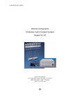
Perfusion
Valve Controller
Model VC-6M
Publication 5711-001-REV-B
WEEE/RoHS Compliance Statement
EU Directives WEEE and RoHS
To Our Valued Customers:
We are committed to being a good corporate citizen. As part of that commitment,
we strive to maintain an environmentally conscious manufacturing operation. The
European Union (EU) has enacted two Directives, the first on product recycling
(Waste Electrical and Electronic Equipment, WEEE) and the second limiting the use
of certain substances (Restriction on the use of Hazardous Substances, RoHS).
Over time, these Directives will be implemented in the national laws of each EU
Member State.
Once the final national regulations have been put into place, recycling will be offered
for our products which are within the scope of the WEEE Directive. Products falling
under the scope of the WEEE Directive available for sale after August 13, 2005 will
be identified with a “wheelie bin” symbol.
Two Categories of products covered by the WEEE Directive are currently exempt
from the RoHS Directive – Category 8, medical devices (with the exception of
implanted or infected products) and Category 9, monitoring and control instruments.
Most of our products fall into either Category 8 or 9 and are currently exempt from
the RoHS Directive. We will continue to monitor the application of the RoHS
Directive to its products and will comply with any changes as they apply.
• Do Not Dispose Product with Municipal Waste
• Special Collection/Disposal Required
Table of Contents
Warner Instruments
Perfusion Valve Controller Model VC-6M
1
SUBJECT
PA G E
Introduction ..............................................................................2
Operating Directions................................................................3
Setup ..................................................................................3
AC Conversion ....................................................................5
Instructions for Use ............................................................6
Flow Adjustment ..........................................................................6
Rear Panel ................................................................................6
Maintenance..............................................................................7
Cleaning ..............................................................................7
Warranty ....................................................................................8
Specifications ..........................................................................8
Publication 5711-001-REV-B
Introduction
Warner Instruments
Perfusion Valve Controller Model VC-6M
2
The VC-6M Valve Control System lies at the heart of a multi-valve perfusion
system designed to automate and control the delivery of small quantities of
fluids to Warner Instruments imaging and recording chambers. However, its
flexible design allows the system to be used in many applications not using
Warner equipment.
The miniature solenoid valve assembly is standard with the system.They are
lightweight and made from rugged materials for long life.Valves are dual acting
with both NORMALLY OPEN and NORMALLY CLOSED sides.The NORMALLY
OPEN side is plugged with removable stoppers and when these are removed
solution can flow to waste while the valve is in the off position.
The controller can independently regulate the function of up to six valves.The
system can be purchased in a two or four valve configuration and can be easily
expanded by simply adding more valves.Individual valves can be controlled via
a manual switch or an external digital (TTL) signal.Valve transitions (opened or
closed) occur at full power to insure rapid response times and are then held in
place at less than half power to prevent heat transfer to solutions. An eventmarker pulse, generated each time a valve is switched on, is provided at the
rear of the controller for recording into your acquisition system.
The basic system includes the valve controller, a valve manifold with mounted
valves, connecting cable and an ML Series manifold. The complete system
includes all of the above plus a ring stand, eight 10 cc syringes, a syringe holder, 20 feet of PE-50 tubing and tubing connectors.
Publication 5711-001-REV-B
Operating Directions
Warner Instruments
Perfusion Valve Controller Model VC-6M
3
Before beginning setup, take an inventory of the plastic fittings supplied
with the complete system.These fittings include eight (8) LPE-50 tube-toLuer connectors and eight (8) stopcock-with-Luer connectors. Connectors
are shown below. Basic Systems are supplied with a manifold only.
LPE-50 Luer-to-PE
tubing connector
Stopcock with Luer
connector
ML-6 manifold
Setup
The diagram below shows connections for the VC-6M Perfusion System.
The valve manifold comes with plugs to block flow to the NORMALLY
OPEN flow lines.Remove these plugs and use these ports if a flow-to-waste
system is desired.
In general, the shortest response time of the system will be achieved by
keeping the tubing length between the MANIFOLD and sample as short as
possible.
Publication 5711-001-REV-B
Operating Directions (Cont’d)
4
First, attach the VALVE MANIFOLD to the RING STAND as shown below.
This is followed by insertion of PE-50 tubing into the valve ports on the
VALVE MANIFOLD. Depending on the flow arrangement you’re using (onoff or flow-to-waste), cut either six (6) or twelve (12) pieces of PE-50 tubing long enough to reach from the VALVE MANIFOLD to the MANIFOLD
and from VALVE MANIFOLD to the your waste container.
Attach cut tubing to the output ports on each MINI-VALVE on the VALVE
MANIFOLD by gently pressing into place. Port positions are shown in the
figure on page 4. Place flow-to-waste tubing into the waste container and
attach sample tubing to the perfusion MANIFOLD.
Warner Instruments
Perfusion Valve Controller Model VC-6M
The VC-6M Valve Controller is assembled in the following manner:
Next, attach the SYRINGE HOLDER to the RING STAND. Affix a LUER-TOPE-50 TUBING connector to each STOPCOCK-WITH-LUER connector.
Mount SYRINGES into the SYRINGE HOLDER and attach a prepared stopcock assembly to each SYRINGE. Now cut six (6) pieces of PE-50 tubing
just long enough to run from the LUER-TO-PE-50 TUBING connector (on
the SYRINGE) to the input port on each MINI-VALVE.
Finally, make a connection between the perfusion MANIFOLD and your
sample with PE-50 tubing. Plug the VALVE MANIFOLD into the VALVE CONTROLLER and the system is ready to use.
Publication 5711-001-REV-B
Operating Directions
5
Warner Instruments
Perfusion Valve Controller Model VC-6M
AC Conversion
ATTENTION
PLEASE READ BEFORE APPLYING POWER TO YOUR UNIT!!
The unit has been set to be used with 120 VAC.
If the VAC needs to be changed to 220VAC, enclosed you will find a kit
(power cord (1) and fuses (2)) to be used to convert the unit from 120VAC
to 220 VAC.
The unit uses only one fuse; the second one is sent as spare.
Follow these instructions to change the unit(s) from 120VAC or 220VAC:
Power Entry Module
Fuse holder side view.
Push out drawer to access
the Spare Fuse
Active
Fuse
Step 1
Depending on AC Voltage being
used, turn VAC selector switch
to 110VAC or 220 VAC
Step 2
Carefully, pry open the fuse holder from the inside
by using a small flat screwdriver.
Replace fuse according to voltage being used.
Item # 4630130 Model VC-6 and VC-6M use:
For 120 VAC: 0.50 Amp - 5x20mm Slow Blow
For 220 VAC: 0.25 Amp - 5x20mm Slow Blow
Publication 5711-001-REV-B
Operating Directions (Cont’d)
6
Warner Instruments
Perfusion Valve Controller Model VC-6M
I n s t ru c t i o n s f o r U s e
Flow Adjustment
Flow rates can adjusted by raising or lowering the reservoir holder, as
well as by adjusting the height of each reservoir within the holder.
The table below lists the approximate flow rates for a reservoir at the
specified height with the supplied Tygon‚ tubing.
Reservoir height
Approximate flow rate
61 cm (24 in.)
1.2 ml/min
30 cm (12 in.)
0.8 ml/min
20 cm (8 in.)
0.6 ml/min
Rear Panel
•
The Event Marker output produces a 500 ms logic-level output (+5 V)
each time a valve is turned on. At all other times the Event Marker
output is low (0 V).
•
A 15 pin "D" type female connector is used to connect the VALVE
MANIFOLD (and valves) to the CONTROLLER.
•
A polarized, 3-conductor, IEC320/CEE-22 connector is used for line
(mains) power input to the instrument. A removable cordset,
terminated with a NEMA 5-15P connector, is standard. An alternate
cordset may be supplied when local circumstances dictate different
mains voltages and connections. Contact our offices for details.
•
A fuse holder contains a protective fuse in series with the high side
(brown or black wire) of the mains.The holder accepts 5 x 20 mm
fuses of the type indicated.
Publication 5711-001-REV-B
Maintenance
7
Do not use alcohol, aromatic hydrocarbons or chlorinated solvents for
cleaning.They may adversely react with the plastic materials used to manufacture the system. If salt solution spills on the valve assembly it should be
cleaned as soon as possible with a soft cloth dampened with a mild
solution of detergent and water.
NOTE: Valves must be completely flushed with distilled water after each
use. Permanent damage will result if saline solution is allowed to crystallize
inside the valve.
The exterior of the CONTROLLER may be cleaned periodically to remove
dust, grease and other contamination. It is not necessary to clean the inside.
Use a soft cloth dampened with a mild solution of detergent and water.
Avoid abrasive cleaners.
Warner Instruments
Perfusion Valve Controller Model VC-6M
Cleaning
Publication 5711-001-REV-B
Warranty
Warner Instruments
Perfusion Valve Controller Model VC-6M
8
The VC-6M is warranted to be free from defects in materials and workmanship for a period of two years from the date of shipment. If a failure
occurs within this period, we will repair or replace the faulty component(s)
at our discretion.This warranty does not cover failure or damage caused by
physical abuse or electrical stress (e.g., exceeding specified input limits).
Shipping charges to the factory are the customer's responsibility. Return
shipping of the repaired unit will be paid by Warner Instruments, Inc.
Specifications
Valves
12 VDC /0.046 A, solenoid type
Valve manifold
Teflon material, mounts on a 3/8” or 1/2” ring stand
Tubing
PE-50
Connection Cable
2.4 meter (8 ft.) connecting cable terminated with
quick disconnects on valve end and 15 pin male "D"
type connector on controller end.
Reservoirs
Reservoir Holder
Valve Controller
10 cc capacity syringes
Delrin. Holds eight syringes with thumb screws for
each reservoir.
Typical response times for valves is 2.5 ms
Switch Selection
Manual, Off or External
External Input
+5 V TTL-compatible (BNC Connector)
Event Marker
Logic level pulse 500 ms nominal (rear panel BNC
connector)
Manifold
2/1, 4/1 or 6/1 nominal dead space
Power
110-130 or 200-250 VAC, single-phase, 50/60 Hz, 20 watt
Operating Temperature
10-40° C (50-104° F)
Dimensions (H x W x D)
89 x 203 x 305 mm (3.5 x 8.0 x 12 in.)
Weight / Shipping Weight
3.7 kg (8 lb.) / 4.6 kg (10 lb.)
Publication 5711-001-REV-B