1
ASL 5000
Breathing Simulator
Addendum for RespiSim Software Option
RespiSim Addendum, SW 3.5, Rev.1 © IngMar Medical, Ltd. 2014
Software Version 3.5.0
This page intentionally left blank
RespiSim Addendum, SW 3.5, Rev.1 © IngMar Medical, Ltd. 2014
2
RespiSim Windows
What Is Covered
This addendum to the Operating Instructions of the ASL
5000 High Fidelity Breathing Simulator covers setup and
use of the RespiSim interface software as well as the
optional RespiSim Ventilator Interface Kit (VIK).
Intended Use of the RespiSim Option
RespiSim is intended to create a fully integrated
respiratory simulation experience for training in the
subjects of mechanical ventilation and ventilator
management.
RespiSim is built on immersive simulation and dynamic
clinical reality. With the high fidelity ASL 5000
Breathing Simulator as the lungs of the simulated patient,
it represents a completely new method of teaching the
subject of managing the delicate interactions between a
patient and the ventilator in a truly interactive fashion.
RespiSim gives the instructor the ability to:
— have full control of all aspects of a simulation,
— capture data from the ASL 5000 Breathing Simulator,
the connected ventilator (optional), and the vital signs
monitor,
— provide learners with the patient status using the vital
signs monitor,
— mark and annotate events, and
— replay the compiled recording during
debriefing sessions or for classroom
instruction.
Developed in collaboration with leading educators,
preconfigured RespiSim curriculum modules save
instructor time by providing a comprehensive, multimedia package of materials that describes and
demonstrates a concept or scenario within the subject of
mechanical ventilation.
Precautions
WARNING !
- NOT FOR USE ON A PATIENT The ventilator data acquisition and storage system of
RespiSim is not intended to monitor, chart, or store
data coming from actual patients or for the purpose of
assisting in clinical decisions regarding actual
patients1
1. *Please contact Bridgetech Medical at bridgetechmedical.com for
information about their system for electronic record keeping of
respiratory data in stationary care.
1
RespiSim Windows
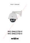
The RespiSim tab is the furthest to the right on the ASL
5000 Windows Manager. Pressing the
button loads RespiSim.
3
RespiSim Addendum, SW 3.5, Rev.1 © IngMar Medical, Ltd. 2014
Figure 1-0 RespiSim Tab on the Window Manager
RespiSim Windows
Instructor Dashboard Guide
1.1
Instructor Dashboard Guide
RespiSim Addendum, SW 3.5, Rev.1 © IngMar Medical, Ltd. 2014
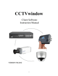
Figure 1-1
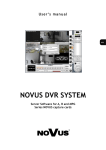
the ability to implement ventilator (reference) settings,
vital signs, and ABG values that, together, represent a
patient’s current status.
Instructor Dashboard
The Instructor Dashboard greatly simplifies simulation
management and gives the instructor full control of all
aspects of a simulation.
A: Control and Navigation Buttons - Start / stop and
invoke a pause patient model as well as navigate to other
tabs and windows within the ASL 5000 Software,
including Interactive Control Panel (ICP), RespiSim Debrief
panel, Run Time Home, Vital Signs Monitor (VSM), and
EventMarkers.
B: Display Parameters - The most significant parameters
from the ASL 5000, the connected ventilator (optional),
or the simulated Vital Signs Monitor (VSM) can be
displayed in these six fields. All fields can be changed
anytime by clicking on the parameter name.
C: Lung model and Vent Settings - Create patient models
using the simulation script editor and upload .vr3 files
into the instructor dashboard to show learners the
progression of a patient’s disease state. The instructor has
D: Current Module File (.xml) - This is the file that is
called from the Load button at the bottom left of the
Dashboard window.
E: Instructor Guide - Provides step-by-step instructions
on running the simulation to meet learning objectives (in
PDF format).
F: Preferences File (.rsp) - Many aspects of the visual
appearance of the RespiSim interface may be predefined
via sets of preferences. These preferences allow the
instructor to customize the instructional environment to
the specific subject being taught. For example, only
those parameters most relevant to the subject should be
made visible, thus avoiding unnecessary clutter and
informational overload.
G: External Device Controllers - These controls are for
the external SpO2 pulse oximeter and the CO2 infusion
for users of the RespiPatient® option.
H: lnstructor-Driven Patient Vitals - include ABGs,
chest X-rays, lab results, as well as heart and lung
sounds.
4
RespiSim Windows
RespiSim Debrief Window
1.2
RespiSim Debrief Window
A: Module Inventory – Displays the available patient
models created for a RespiSim module (e.g. NIV2000)
B: Control and Navigation Buttons – Start/Stop
simulation, invoke pause patient model, and freeze the
display for review. Adjust between Waveform, Loop, or
Trend view. View current patient model. Open event
markers window. Open the recorded simulation via the
<Open Playback Mode> button. Navigate to the
Interactive Control Panel.
C: Event Graph – Shows each breath based on Vt, event
markers invoked by the instructor (e.g. “O2%
increased”), and any alarms or automated changes to a
ventilator (VIK option) or to the ASL 5000 simulator.
5
D: Real Time Graphics - Real time graphics are provided
in the RespiSim Debrief panel as either a complement of
waveforms or loops (for pressure, volume, and flow), or
trends of a selection of the numerically displayed
parameters.
E: Numeric Parameters - Display up to 18 parameters
collected from the ASL 5000, the attached ventilator
(VIK option), and the simulated Vital Signs Monitor (VSM).
RespiSim Addendum, SW 3.5, Rev.1 © IngMar Medical, Ltd. 2014
Figure 1-2 RespiSim Debrief Window
RespiSim Windows
RespiSim Window in Playback Mode
RespiSim Addendum, SW 3.5, Rev.1 © IngMar Medical, Ltd. 2014
1.3
RespiSim Window in Playback
Mode
B: Event Graph - The Event Graph (or time line view)
shows the entire simulation based on each breath
(yellow bars) and any documented changes from the
EventMarkers. The green vertical cursor can be moved
Figure 1-3 RespiSim Window in Playback Mode
The RespiSim tab on the ASL 5000 host software’s
Window Manager provides a coherent and full featured
debriefing screen that brings together all relevant
information from a simulation session.
A: Open Playback Mode - When the <Open Playback
Mode> button in the control area of the RespiSim
interface window is clicked, the visual appearance of the
left portion of the window changes and all the pertinent
information for the recorded simulation is displayed,
together with a play/end-of-track/beginning-of-track set
of buttons.
throughout the simulation timeline to different positions
that reveal the associated parameters, waveforms, and
events at various points in the simulation.
C: Real Time Graphics - Real time graphics are provided
in the RespiSim Debrief panel as either a complement of
waveforms, loops, and trends of a selection of the
numerically displayed parameters.
D: Numeric Parameters - The field on the bottom right
of the RespiSim Debrief panel allows the display of up to
18 parameters collected from the ASL 5000, the attached
ventilator, and the simulated vital signs monitor (VSM).
6
RespiSim Windows
Vital Signs Monitor (VSM)
1.4
Vital Signs Monitor (VSM)
1.6
RespiSim Preferences Window
The RespiSim Preferences window gives the user the
ability to configure the module visibility prior to running
the simulation.
Figure 1-4 Vital Signs Monitor
The Vital Signs Monitor displays several vital parameters
to the learner, but is also capable of displaying X-rays,
ABGs, and lab results, upon request.
1.5
Event Marker Window
Figure 1-6 RespiSim Preferences - Module Tab
The EventMarker window allows the user to add debrief
points to the simulation in real-time. When the student
makes an adjustment to the patient, e.g. increasing the
O2%, the instructor can mark on the Event Graph when
this happened. The instructor can also toggle the marker
to remain on (or latched) during a procedure (e.g.
suction), creating a time line in the Event Graph
indicating the duration of the procedure.
7
RespiSim Addendum, SW 3.5, Rev.1 © IngMar Medical, Ltd. 2014
Figure 1-5 EventMarker Window
RespiSim Windows
Module Tab
1.7
Module Tab
In this tab, the instructor can define the path for the *.vr3
patient profiles used in the simulation, provide a short
description of the module, and define the path to the
saved preferences file in *.rsp format.
.
Figure 1-8 RespiSim Preferences - Parameters Tab
RespiSim Addendum, SW 3.5, Rev.1 © IngMar Medical, Ltd. 2014
Figure 1-7 RespiSim Preferences - Event Graph Tab
Parameters Tab - In this tab, the instructor can define up
to 18 visible parameters for the RespiSim Debrief window.
The colors of the parameter fields and any scaling can
also be defined in this tab.
Event Graph Tab - In this tab, the instructor can choose
to include the automatic responses from the VIK (option,
AutoScan), allow manual data charting from ventilator
(Student Scan), as well as set the text labels for the
EventMarkers window. Background colors and the ability
to “latch” events are also configured in this tab.
8
Plug & Play Modules
2
Plug & Play Modules
Most preconfigured curriculum module/packages
supplied by IngMar Medical are accompanied by a
Scenario Concept Presentation (SCP) that prepares
students for the immersive hands-on simulation. The
slide presentation is in a movie format (mp4) and has a
full voice-over for self-study. It can be accessed in the
module specific folder.
Figure 2-1 RespiSim Window in Playback Mode
9
RespiSim Addendum, SW 3.5, Rev.1 © IngMar Medical, Ltd. 2014
2.1
Getting Started with RespiSim
3
Getting Started with
RespiSim
NOTE: This section assumes that the user has a basic
understanding of running the ASL 5000 Breathing
Simulator with the ASL 5000 Software.
Click on the file filename.xml to load a module.
By default, the RespiSim modules are located in the
C:\Program Files (x86)\ASL Software
3.5\RespiSim_Modules folder. Select and open the
desired simulation folder, then double-click the
filename.xml file for that simulation (e.g. NIV2000.xml).
RespiSim Addendum, SW 3.5, Rev.1 © IngMar Medical, Ltd. 2014
NOTE: The RespiSim option can run in demo mode in
the same way as the main software. This can be useful in
setting up modules and testing different patient
transitions, etc.
After starting the software that will create the connection
to the ASL 5000, select the RespiSim tab in the Windows
Manager and click the
button.
Figure 3-2 Selecting a RespiSim Module
This will first open the RespiSim Debrief window, and
then the Instructor Dashboard window.
Event 1, etc.).
The module’s settings will now appear in the Instructor
Dashboard’s various tabs (e.g. Initial Settings, Change
Figure 3-3 Instructor Dashboard After Module Loading
Figure 3-1 Instructor Dashboard After Start
Click on the
button.
All of the patient profiles (.vr3 files) used for this module
can now be seen in the “Module Inventory” field of the
RespiSim Debrief Window..
This will allow the user to upload a RespiSim module
from the RespiSim module inventory (default location).
Figure 3-4 Module Inventory on Debrief Window
10
Getting Started with RespiSim
To show the Instructor Guide, click on the
To gain a better understanding of what the learner
should recognize during the simulation, click on the
button inside the Initial Settings tab.
button on the Instructor Dashboard. The Instructor Guide
provides all of the information necessary to set up and
facilitate a simulation according to the learning
objectives. The instructor guide is a PDF document and
requires Adobe Reader to open.
Figure 3-7 Instructor Actions
Figure 3-5 Instructor Guide
To start a simulation, click the
button on the Instructor Dashboard. This loads the initial
patient model (e.g. 2000NIV.vr3) which can be
examined by pressing the
button. The
button changes to yellow with an “Initial Settings
Enabled” label. The purple "streaking" bar above the
Initial Settings tab shows which Event tab is currently
running.
Click the
button to start the simulation.
To show the patient’s background information, click the
button near the bottom right of the
Figure 3-8 Enabling Initial Settings
Figure 3-6 Initial Assessment
11
RespiSim Addendum, SW 3.5, Rev.1 © IngMar Medical, Ltd. 2014
Instructor Dashboard..
Getting Started with RespiSim
When the “Select An Output File” window opens, enter
path and a meaningful file name for data results file sets.
You may direct the output files to the specific module’s
Support Files folder (e.g. NIV 2000 support files) or into a
different folder of your choice. This results data will be
used for debriefing later. Click “OK” to start the
simulation.
Click the Change Event 1 tab, next to the Initial Settings
tab, to view how the instructor can control the further
simulation sequencing. Here, various instructor settings
can be enabled with the click of the
button. These instructor settings reflect possible
treatment decisions made by the learner (e.g. changing
ventilator settings) and the associated changes in patient
status. The “red to green” background color scheme
symbolizes the transition from the least to the most
optimal treatment modality at that stage of the scenario.
It should be noted that, for a successful conclusion of a
simulation stage (the Change Event), the instructor will
always have to ensure that the learner arrives at the
“green end” of the spectrum; otherwise it would not
make sense to proceed with subsequent Change Events.
Figure 3-9 Saving a Data Set
Any time before or during the simulation, the instructor
can display the Vital Signs Monitor (VSM) by clicking the
button on the Instructor Dashboard.
RespiSim Addendum, SW 3.5, Rev.1 © IngMar Medical, Ltd. 2014
NOTE: A 2nd monitor is highly recommended for a
realistic teaching environment. The software window for
the VSM is sized to fill a 1366 x 768 screen (FWXGA).
Figure 3-11 Change Event Progression
NOTE: For debriefing purposes, the changes made by
the learner should be entered into the EventMarkers
window. Click the
button to open the
window. Event markers are pre-set in the modulespecific preferences and allow individual notes to be
entered in the fields provided. In some modules, these
Figure 3-10 VSM Screen with ABG
As mentioned above, the instructor can also provide
additional information such as X-ray images, ABGs, and
lab results to the learner by clicking the
buttons.
12
Getting Started with RespiSim
notes may contain questions the instructor can use to test
the learners’ knowledge and enter additional text (the
answers) into the fields.
button to view the Instructor Guide
document. Scroll to the bottom of the document to find
discussion materials, questions, and debriefing points
Figure 3-12 EventMarker Entries
Figure 3-14 Instructor Guide: Debriefing Q&A
To review the concluding notes for a Change Event tab,
click the
button at the bottom right of
the Debrief Window.
Click the
button on the Instructor
Dashboard to open the RespiSim Debrief window. From
the RespiSim Debrief window, click the
button.
The visual appearance of the left portion of the window
changes and all the pertinent information from a
recorded simulation can now be displayed, together
with a play/end-of-track/beginning-of-track set of
buttons.
Once the simulation is complete, the instructor can go to
the RespiSim Debrief window to review the simulation.
Go to the Initial Settings tab, and click the
Figure 3-15 Starting Playback for Debriefing
Open a recorded simulation by clicking the folder
browse button on the left of the window.
13
RespiSim Addendum, SW 3.5, Rev.1 © IngMar Medical, Ltd. 2014
Figure 3-13 Final Assessment
Getting Started with RespiSim
Browse to the appropriate *.tdms file to open all the
features of the recorded simulation module.
autoscans or studentscans are available only with the
VIK option. All other events can be invoked during any
simulation and can be set via the RespiSim Preferences
window, accessed via the Instructor Dashboard and the
RespiSim Debrief window.
In playback mode, a vertical cursor is used for
navigation. The Event Graph will always show the full
length of the recorded simulation, but the Real Time
Graphics (waveforms and loops, see below) are limited
to the 20 seconds around the location of this cursor on
the time line. Similarly, the numeric parameters shown
are those from the time associated with the cursor
position. Moving the cursor to different positions based
on visual clues in the Event Graph will thus reveal the
associated parameters, waveforms, and loops for that
time.
Figure 3-16 Selecting a *.tdms File for Debriefing
Click the play button.
The Event Graph can be enlarged to cover the full height
of the RespiSim window by clicking on the down-arrow
in the bottom left of the field.
In this view, all bars are labeled for better orientation.
Clicking on the up-arrow in the same location as before
will collapse the field to its regular size.
Use the end-of-track/beginning-of-track buttons for easy
navigation to the first or last use of a specific patient
model (*.vr3-file) during a simulation. The cursor in the
Event Graph will be placed in this location so that
waveforms and numeric values can be read off at
transitions between different patient states with ease.
RespiSim Addendum, SW 3.5, Rev.1 © IngMar Medical, Ltd. 2014
The height of the yellow bars in the Event Graph
represents variations in tidal volumes. The colored blips
represent events that have been recorded by the
instructor for debrief points.
Figure 3-18 Cursor "Hovering" for Marker Details
Figure 3-17 Event Graph During Debriefing
Aside from any events the instructor might enter during a
simulation via the EventMarker window, there are several
other markings in the Event Graph. From the top, these
are markers for the automatic and student scans as they
occur during the simulation. Below these, there is a
maximum of five possible alarm-related marking bars.
These are associated with ventilator alarms and indicate,
for example, the existence of an alarm condition,
operation of the ventilator’s alarm silence function, or
use of the alarm reset button. The alarm states and the
While the Event Graph is expanded, placing the cursor
over the Instructor Events marked in the file ("hovering")
will bring up any comments that had been recorded with
the specific event.
The Event Graph shows a vertical cursor line that is used
to navigate inside a selected recording. This is the
primary method of accessing a particular point in time of
a recording. The play button on the top left also has a
step back/forward feature. Clicking on these elements
forwards the starting point of the playback to the next (or
14
Getting Started with RespiSim
previous) change of patient parameter file. Clicking the
<Play> button starts recorded data from the point of the
cursor. The numeric parameters in the field on the
bottom right change as the recording moves along, and
so do the waveforms/loops in the Graphics field.
Playback provides an excellent way for viewing data for
the purpose of debriefing after a simulation session or to
demonstrate effects in the context of e-learning, as a
stand-alone. Real time graphics are provided in the
RespiSim Debrief window as either:
— a complement of waveforms for flow, pressure, and
volume
— flow/volume and pressure/volume loops, or
— trends of a selection of the numerically displayed parameters
Significantly, the parameters include not only breath
parameters such as tidal volume or peak pressure, but
also ventilator mode and alarm settings as well as patient
status vitals (click on the field names to see the many
choices in a drop-down menu).
In playback mode, data will always be visible only in the
format in which it was collected (waveforms, loops, or
trends). The time-length of the window for waveforms is
determined by the choice made in the Run Time Home
window (default is 20s). Loops are, by default, not autoscaled, similar to the loops found in the Run Time Home
window. The trend view is configurable from the
graphics field itself, by clicking on the “Select Trends”
button at the bottom. The trends of any of the numeric
parameters displayed to the right of the graphics field as
part of the Parameter List may be switched on or off,
including a choice for “all off” or “all on.”
The field on the bottom right of the RespiSim interface
window allows the simultaneous display of up to 18
parameters collected from the ASL 5000 internal
calculations, the physical ASL 5000 parameters,
attached ventilator (VIK option only), and Vital Signs
Monitor.
Because of space constraints, the label text of the
parameters might exceed what is visible in the respective
field under the numeric value. Hovering over any of the
label fields, however, will reveal the full name and
physical unit of parameters in a “bubble.”
Since ventilator parameters are generally retrieved based
on the AutoScan settings, and are only updated every 20
or 30 seconds, the values are not quite real time. For this
reason, it is recommended to always give priority to
parameters coming directly from the ASL 5000 Breathing
Simulator when possible. These parameters are
calculated for every breath and can provide more timely
information in cases where a particular parameter is
available from both the simulator and the ventilator (e.g.
tidal volumes, peak pressures, etc.).
Figure 3-19 Parameter Labels on Debrief Window
The parameter fields may be populated with any of the
90+ breath parameters. The color background of these
parameter fields can be adjusted based on user
preference. To change the background colors, open the
RespiSim preferences window from the Dashboard or
the Debrief view. Colors can be used to group
parameters of the same type together (e.g. parameters
from the ASL 5000, the ventilator, and the Vital Signs
Monitor).
RespiSim Addendum, SW 3.5, Rev.1 © IngMar Medical, Ltd. 2014
15
Figure 3-20 Selecting a Parameter for Debriefing
Authoring Modules
Instructor Guide
4
Authoring Modules
IngMar Medical has developed complete modules
ranging from understanding modes of ventilation to more
specific topics like dissynchrony. As an instructor
becomes more familiar with the RespiSim concept,
custom modules can be created and submitted to IngMar
Medical for review.
As stated above, the learning goal is to help the learner
arrive at the optimal settings based on the definition of
the module. As the learner makes adjustments to a
ventilator based on the patient model and vitals
feedback, the instructor can then enable new patient
models (from left to right in a Change Event tab). As the
simulations become more complex, the instructor can
add new Change Event tabs with changing patient models
in an effort to guide the learner to the optimal outcomes.
4.2
Saving Settings
It is good practice to frequently save settings while
setting up the RespiSim modules. The format of the
module is in *.xml format. By clicking the
button on the Dashboard, the instructor
can save and overwrite the simulation file until the
module development is complete. When the *.xml-file is
saved, a support files directory is automatically created
that holds all of the patient models, lab results file,
instructor guides, etc. for that module. Because of this, it
is recommended to create a new folder inside the
..\RespiSim Modules directory where the *.xml-file and
all files for this module (support directory) will be saved
while building the simulation.
We recommend to give the *.xml-file the same name as
the folder that is created within the ..\RespiSim Modules
directory as shown below.
The recommended method for creating a custom module
is shown below.
4.1
Instructor Guide
An Instructor Guide Template & Authoring Guide is
provided to outline the steps the instructor must take for
the preparation of RespiSim modules. The Instructor
Guide provides the following:
•
RespiSim Addendum, SW 3.5, Rev.1 © IngMar Medical, Ltd. 2014
•
•
•
•
•
•
•
General Scenario Information
—Information about the module, developer, Intended
learners
Case Description
—Summary of the background of the patient and the
environment for the upcoming simulation
Learning Objectives
—A listing of the objectives expected by the learners
Scenario Overview
—Includes the Initial Assessment and Change Events
to be used
Patient Information and History
—Details about age, setting, history, vitals, labs, etc.
Initial Assessment
—Detailed assessment and files used in the simulation
in the Initial Settings Tab
Change Events
—Breakdown of each Instructor Setting group within
a given Change Event. This covers vent reference
settings, lung models to use, vitals, etc.
Debriefing Planning and Questions
—Information on preparing for the debrief session and
what pertinent questions should be asked at the
conclusion of the simulation and debrief.
Figure 4-1 Module File Naming
4.3
Instructor Settings Columns
The event tabs encompass several Instructor Settings
columns which hold the characteristics of each step of a
patient scenario. The user should always start with the
Initial Settings Tab. Each column can be populated in the
four additional Change Event tabs based on the module
being created.The instructor can fill each individual
column with vent reference settings (the ventilator
settings expected for a particular state), vital signs and
ABG values that pertain to the scenario.
16
Authoring Modules
Patient Models
Begin with an initial baseline and, based on these values,
create different treatment pathways (vent settings) a
learner may choose to manage the patient’s status (vitals
and ABG values). As you move from left to right (i.e., red
to green), provide the least optimal to the most optimal
treatment decision (vent settings) and how the patient’s
body reacts to these changes (vitals and/or ABG values).
The instructor should develop each patient model before
creating the RespiSim module. This is best done in the
demo mode of the ASL 5000 software. Patient models
can be designed and placed anywhere on a computer,
but it is recommended to keep all *.vr3 files within the
..\vars directory where the ASL 5000 software is installed
for ease of searching for the new patient profiles.
4.5
View Lung Model
After a patient profile is added to the RespiSim
environment, the instructor has the ability to verify the
lung models used by clicking the
button in any of the settings columns. From this window,
the instructor can edit the current model as needed by
clicking the
button. Please refer to the
ASL 5000 User’s Manual for information on editing a
patient model.
Figure 4-2 Setting Values in the Columns of the Instructor
Dashboard
4.4
Patient Models
To add a patient model to the simulation, click the folder
icon at the top of each settings column. It is highly
recommended to always start with the Initial Settings tab
for the first state of the patient.
Figure 4-3 Adding Patient Models to RespiSim Modules
17
Figure 4-4 Building the Patient Model (R and C)
RespiSim Addendum, SW 3.5, Rev.1 © IngMar Medical, Ltd. 2014
The patient models (*.vr3 files) are instructor-defined and
-developed models to be used at different times during
the scenario simulation. Patient models can be designed
to include various compliance, resistance, and effort
settings that represent the diseased or improving states of
a patient while on the ventilator. Patient models can be
passive and only respond to the ventilator, or
spontaneously breathing, thus requiring synchrony in the
ventilator settings. These models can be put into the
Instructor settings columns on the Instructor Dashboard to
represent the advancement of a patient’s condition from
initial state to final assessment.
Authoring Modules
Right-Click Options
4.6
Right-Click Options
Right-clicking inside of any of the editable fields within
the Instructor Settings columns enables several features.
Figure 4-5
4.7
Highlighting
It is good practice to highlight specific parameter
changes as you progress through the scenario. In the
plug-and-play modules, the vent settings that need to
change in order for the patient to reach optimal status,
are highlighted. Right click on any Instructor Settings
column and the drop-down menu will appear. Click on
the “Enable/Disable Highlighting” option. From the
Parameter Highlight Configuration window, select the
parameters you want to highlight with a check mark and
click “Close” for the changes to take effect.
Figure 4-6 Right-Click Options on Instructor Dashboard
•
•
•
•
•
•
•
RespiSim Addendum, SW 3.5, Rev.1 © IngMar Medical, Ltd. 2014
•
Copy Column – Copy all data from a single column
Copy All Columns – Copy all columns from a Change
Event tab
Paste Column – Paste copied data into a single column
Paste All Columns – Paste data into all columns within
a Change Event tab
Enable/Disable Highlighting – Highlight specific parameters within a column
Enable/Disable Pneumo Settings – Individual column
tension pneumothorax control for the RespiPatient®
option
Enable All Pneumo Settings – All Change Event column tension pneumothorax control (enable) for the
RespiPatient® option
Disable All Pneumo Settings – All Change Event column tension pneumothorax control (disable) for the
RespiPatient® option
Figure 4-7 Highlighting Options on Instructor Dashboard
With Mode highlighting set for the ventilator reference
settings, the result looks like this.
Figure 4-8 Vent Reference "Mode" Highlighting
18
Authoring Modules
Instructor Actions
4.8
Instructor Actions
The instructor can enter information into the Show
Instructor Actions windows for all settings columns and
Change Events. The information in each Instructor Actions
window is based on the choices made by the learner.
This is where the instructor or physician can agree or
disagree with a treatment choice made by the learner.
Comments entered here are also intended to coach the
instructor on what to say or do depending on the
information inside the window.
have the volume and speakers on to hear these sounds. It
may help to have external speakers when using this
option.
Figure 4-10 Authoring Scenario Sounds, Standard Method
Figure 4-9 Authoring Instructor Actions
4.9
Lung and Heart Sounds
Figure 4-11 Authoring Sounds, RespiScope™ Method
19
RespiSim Addendum, SW 3.5, Rev.1 © IngMar Medical, Ltd. 2014
RespiSim provides two methods for working with lung
and heart sounds. The first method is to add sounds to
the View/Edit Lung Sounds and/or View/Edit Heart
Sounds windows directly as *.wav or *.au files for
playback from the PC’s speaker. Right-clicking the
or the
buttons opens
the edit window from the Instructor Dashboard. The user
can add a description about the sound file in the
Description: box. Clicking on the folder icon allows the
instructor to browse for an appropriate sound file. The
instructor can preview the sound directly from this
window by clicking the play button
inside the media
player, or by clicking the
button. Clicking <OK> closes this window. During a
simulation, the instructor can click the <Lung Sounds>
or <Heart Sounds> buttons at any time to hear the
sound. The computer running the simulation will need to
The second method requires the IngMar Medical
RespiPatient® option in combination with a dedicated
Cardionics SimScope™. With this option, the user can
run IngMar Medical’s RespiScope™ software to
manipulate nine different lung, heart, and bowel regions
on the RespiPatient® manikin to provide realistic sounds
directly to the learner via the SimScope™ stethoscope.
The RespiScope™ software gives the instructor the ability
to save specific sound file settings to a *.car file, a
playlist that assigns sounds to the nine listening regions
of the RespiPatient® manikin. Similar to the first method,
instead of loading a *.wav file via the folder icon, the
instructor would load the *.car file.
Authoring Modules
Chest X-ray
The appearance of the Lung Sounds and Heart Sounds
windows changes (see Figure 4-11, page 19) to allow the
user direct access to the RespiScope software. The
RespiScope™ software can also be opened directly from
the Initial Settings tab via the
button. To learn more about using the RespiScope
software, please see the RespiPatient® manual.
Perform a "Save As" and make sure to save the image as
a *.jpg and include the Large or Small notation for ease
of loading into the RespiSim software.
4.10 Chest X-ray
Upload chest X-rays from your EMR system/archives as
appropriate to allow learners to request them as
additional information on patient status. The x-rays are
available when the Vital Signs Monitor screen is open.
The RespiSim software can use two image sizes based on
instructor preference:
— Large X-ray – 600 x 600 pixels
— Small X-ray – 300 x 400 pixels
NOTE: Adding X-ray images to the RespiSim software is
explained below using Microsoft Paint application:
Load the X-ray image file into Paint.
Click the Home tab and then select
the Resize and Skew window
Figure 4-12 Sizing X-rays - 300 x 400 pixels
. This opens
RespiSim Addendum, SW 3.5, Rev.1 © IngMar Medical, Ltd. 2014
Check the
radio button to make sure the units are
in pixels.
—When creating the Large image, set the horizontal
and vertical values to 600 pixels.
—When creating the Small image, set the horizontal
to 300 and the vertical to 400 pixels.
NOTE: Depending on the original image aspect ratio,
cropping will be necessary to arrive at the required pixel
counts without distortion. Remember that you can also
add margins if cropping would eliminate important parts
of the image.
Click <OK> and the image sizing is complete.
Figure 4-13 Sizing X-rays - 600 x 600 pixels
In the above example, the 300 x 400 pixel image is
slightly distorted, because the original image was in a
square format.
20
Authoring Modules
Lab Results
Loading the X-ray files into the RespiSim environment
1. Right-click on the
button from the
Instructor Dashboard. This opens the View/Edit X-ray
Information window.
The Small image displays to the right of the Vital Signs
Monitor window.
Figure 4-16 Small X-ray Image Display
5. Select <OK> to close the window.
Figure 4-14 Viewing X-ray Images
1.
2. There are two folder icons that are now used to load
the Large (Full Screen) and Small images that were
created previously.
3. Click either folder icon and load the appropriate images
Create lab results to allow learners to examine the use of
laboratory tests for managing mechanical ventilation.
Open a simple text editing application like Notepad on
the IngMar Medical computer provided. Type the lab
test name on the left (i.e. BUN) and then click the tab
button on the keyboard once. Next, type the numerical
value with correct units (i.e. 21 mg/dL). Click the Enter/
Return button on the keyboard to add another lab result.
Save the lab results as a *.txt file
(i.e. NIV2000labresults.txt) in the module’s support files
directory.
Figure 4-17 Lab Results Display
Figure 4-15 Large X-ray Image Display
21
RespiSim Addendum, SW 3.5, Rev.1 © IngMar Medical, Ltd. 2014
4. Select the radio button
to assign
which image size the instructor should display as the
default during simulations (it is not possible to show
both images, but the choice can be reversed at any
time later). The Large (Full Screen) image displays on
top of the Vital Signs Monitor window.
4.11 Lab Results
Authoring Modules
ABG Values
Right-click the
button from the
Instructor Dashboard and select the lab results file by
clicking the folder icon in the dialog window that opens.
Figure 4-18 Lab Results Display
4.13 Assessments
The Instructor Dashboard’s Initial Settings tab provides
the
button. This button is intended to
provide the learner with a complete patient health
history in order to aid them in preparation for the patient
encounter. In the plug-and-play modules created by
IngMar Medical, background information is provided,
which includes the following items:
— demographic data,
— chief complaint,
— history of present illness,
— past medical history,
— social and environmental history.
This information helps to provide a more accurate
picture of the current patient. The instructor can use this
window to provide similar details about the patient and
the ensuing simulation when authoring. Simply enter the
desired text into the window and click <OK>.
NOTE: For displaying lab results, the Vital Signs Monitor
window will be opened.
4.12 ABG Values
RespiSim Addendum, SW 3.5, Rev.1 © IngMar Medical, Ltd. 2014
The ABG values are entered directly into each settings
column within the Dashboard Change Events. When a
simulation is running, the ABG values are displayed from
the column that is “Enabled.” Upon a learner’s request,
the Vital Signs Monitor window can also display the
ABG by clicking the
button.
Figure 4-20 Initial Assessment Window
Figure 4-19 ABG values Display
NOTE: For displaying ABGs, the Vital Signs Monitor
window will be opened.
22
Authoring Modules
Parameters on Instructor Dashboard
Each Change Event tab also incorporates an
button where the instructor can
provide feedback and/or directions for how to continue
the simulation. For example, the learner may reach the
Optimum Settings column in Change Event 1, leading to
the following Assessment.
Click on the parameter drop-down to select from the list
of 90+ parameters and remember to save the settings.
Figure 4-21 Change Event Assessment Window
4.14 Parameters on Instructor
Dashboard
Customize modules by selecting up to six parameters
(ASL, Vent, or Vital) visible to instructors on the
Instructor Dashboard. Select parameters that are crucial
to the progression of the specific simulation. For
example, if a learner decides to initiate a lung protective
strategy (LPS) on the ventilator (decrease Vt, increase
RR), the instructor may want to have a visual of those
setting changes (using either the ’ASL’ or ’Vent’
parameters) in order to know when to activate the
patient model appropriate for the LPS.
23
RespiSim Addendum, SW 3.5, Rev.1 © IngMar Medical, Ltd. 2014
These parameters are intended to assist an instructor
who may not be present in the simulation room or have
a direct view of the changes being made on the
ventilator.
Figure 4-22 Selection of Parameters for Display on the
Instructor Dashboard
The RespiSim Environment
Optional RespiSim VIK Hardware System Components
5 The RespiSim
Environment
RespiSim Addendum, SW 3.5, Rev.1 © IngMar Medical, Ltd. 2014
Ventilator management is a critical responsibility that
demands sophisticated skills. The RespiSim system is
capable of providing a sophisticated training
environment for many aspects of the tasks related to
ventilator support. The mechanical ventilation
curriculum in respiratory care programs has, of course,
the most need for such training. On the other hand, other
caregivers, such as physicians and nurses, also have to
be trained in the basic handling of ventilators. They need
to have the ability to recognize potentially dangerous
events or challenging patient conditions. Scenarios for
teaching those skills can be taught within the scope of
the RespiSim system. The instructor’s task is to create
and implement exercises that will greatly enhance the
depth and speed with which such skills can be learned.
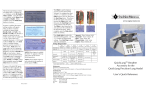
5.1
Optional RespiSim VIK Hardware System Components
Aside from the RespiSim modules in the ASL 5000 host
software, the RespiSim System comprises an optional
hardware component, the Ventilator Interface Kit (VIK),
that connects a “Bridge” directly to a ventilator’s serial
data port (please see specifications in the ASL 5000
User’s Manual for a list of compatible ventilators).
Additionally, a SQL database environment for the
captured data coming from the Bridge is installed on the
PC. This database is then accessed by RespiSim to make
real ventilator data available for simulation exercises.
IngMar Medical has partnered with Bridgetech Medical,
a specialist in electronic charting systems for respiratory
care environments, to integrate data from a wide range
of ventilator manufacturers. For more information on
Bridgetech Medical solutions for electronic charting,
please visit www.bridgetechmedical.com.
Figure 5-1 Typical attachment of VIK to Ventilator
24
The RespiSim Environment
Optional VIK Software Installation
5.2
Optional VIK Software Installation
If you purchased the optional VIK along with the
RespiSim option for the ASL 5000, the installation of the
database environment necessary for operation of the VIK
has already been performed and the system is prepared
for use.
With the VIK software installation, there will be two
icons on the host computer desktop. The first is called
the AutoScan app, the other is called the StudentScan.
Figure 5-2 AutoScan and StudentScan Icons
The AutoScan application performs, as its name implies,
the frequent automatic scans of ventilator data that
populate the database for ventilator parameters to be
included into the simulation data sets.
The StudentScan application is a program that would be
loaded onto a tablet device with infrared or WiFi
capabilities when used in a real ICU environment for the
purpose of patient charting. Both applications take
snapshots of ventilator data, which, in the case of
StudentScan, can also be augmented with annotations by
the caregiver for properly qualifying a patient’s status.
Optional VIK Hardware Setup
Components necessary for VIK:
•
•
•
25
ASL 5000 and host computer
Router with two or three Ethernet patch cables (depending on whether the user wants to use the VIK
wirelessly or hard wired)
NOTE: On the back of the router, only use ports 1-4
(never the internet port)
Ventilator Interface Kit (VIK), consisting of
—Fusion Bridge (black box) with power cord
—Short Cat-5 Ethernet cable
—Ventilator specific serial adapters
—Blue/yellow USB-to-serial adapter combination (labeled as Fusion)
—All power cords and supplies
The VIK can be connected to the router as a wireless or
hard-wired configuration (IngMar Medical recommends
hard-wiring the VIK to the router).
Hard-wired configuration
a) Connect quantity three Ethernet cables to the back
of the router, and then to the:
—lPC
—ASL 5000
—Fusion Bridge
b) Connect power cables to all four components.
—PC with power cord
—ASL 5000 with power cord
—Router with power cord (LEDs will blink once device is plugged in, there is no On/Off switch)
—Fusion Bridge with power cord (LED light on front
of Fusion Bridge will light up, there is no On/Off
switch)
Connect to ventilator
—Blue/yellow USB-to-serial adapter combination
connects to the Bridge with its USB end.
—Connect short Ethernet cable from the VIK case to
the other end of the blue/yellow adapter combination.
—Connect the other end of the Ethernet cable from
the blue/yellow adapter combination into the appropriate ventilator specific adapter (see list in the
VIK case or in the ASL 5000 User’s Manual).
—Plug ventilator specific adapter into the communications port (Serial / MIB / LTV ports, etc.) on the
ventilator (typically found in the back).
For an overview of the configuration, please see Figure
5-3 on the next page.
RespiSim Addendum, SW 3.5, Rev.1 © IngMar Medical, Ltd. 2014
5.3
Connections:
The RespiSim Environment
RespiSim Addendum, SW 3.5, Rev.1 © IngMar Medical, Ltd. 2014
Optional VIK Hardware Setup
Figure 5-3 RespiSim Ventilator Interface Kit Setup
26
The RespiSim Environment
Launching the VIK Software
5.4
Launching the VIK Software
With all components plugged in:
—With the above settings, the database will update
the ventilator information to the AutoScan application as well as to the RespiSim window in the ASL
5000 software every 10 seconds.
1) Turn ventilator on and connect to a passive test lung
(e.g. IngMar Medical QuickLung), either directly, or
via the SBLVM ("Simulator Bypass and Leak Valve
Module", see ASL 5000 User’s Manual).
2) Start the AutoScan application by double-clicking the
icon on the desktop.
—After connecting to the database, AutoScan should
now start performing scans showing data collected
from the ventilator in the data field.
—In the AutoScan application, click on File, then Configure. Make sure the settings are as follows when
using a pre-configured Fusion Bridge.
Figure 5-5 BridgeTech AutoScan Data View
NOTE: Not all ventilators are capable of updating the
data output at the rate of 10 seconds. Therefore, data
from the ventilator should not be considered fully realtime.
27
RespiSim Addendum, SW 3.5, Rev.1 © IngMar Medical, Ltd. 2014
Figure 5-4 Communication Configuration
The RespiSim Environment
RespiSim Addendum, SW 3.5, Rev.1 © IngMar Medical, Ltd. 2014
Launching the VIK Software
RespiSim Addendum, SW 3.5, Rev.1 © IngMar Medical, Ltd. 2014,
Addendum Rev. 1
28