1
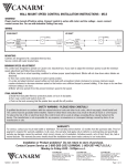
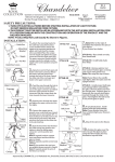
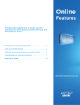
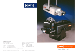
INSTALLATION, OPERATION, AND MAINTENANCE MANUAL
TUBE AXIAL FANS
BTA, WTA, HTA, DDA
The purpose of this manual is to aid in the proper installation and operation of the fans.
These instructions are intended to supplement good general practices and are not intended to
cover detailed instruction procedures. It is the responsibility of the purchaser to assure that the
installation and maintenance of this equipment is handled by qualified personnel.
Inspect all shipments carefully for damage. THE RECEIVER MUST NOTE ANY
DAMAGE ON THE CARRIER’S BILL OF LADING AND FILE A CLAIM
IMMEDIATELY WITH THE FREIGHT COMPANY.
INSTALLATION
1. The fans, when lifted, should be lifted using the flanged ends of the tube or by placing a
sling around the fan tube, and never by the motor, belt tube or motor base.
2. Caution: The fan contains rotating parts and requires electrical service. Appropriate
safety precautions should be taken during installation, operation and maintenance.
3. All electrical work must be done, in accordance with all applicable electrical codes, by a
qualified electrician.
4. Prior to wiring, ensure that the power supply is locked in the OFF position and that the
motor nameplate voltage and the supply voltage match.
5. Be sure to keep all electrical wiring clear of any moving parts.
6. Tighten all nuts, bolts and setscrews to the proper torque settings (see chart), as some
may have loosened during shipping.
7. Before starting the fan, ensure that the wheel rotates freely.
8. On belt driven fans, assure that the belts are aligned and tensioned correctly.
9. Assure that all protective guards and other safety devices are installed properly prior to
fan start-up.
TUBEAXIAL-M
1
10. When hanging tube axial fans, the installer must provide suitable rods and hanging
vibration isolators (both vertical and horizontal applications). Do not support the
ductwork, etc., from the fan. The fan should be supported independently using isolators
designed to support the weight of the fan only.
11. The tube axial fans are suitable for installation either vertically or horizontally however
you must specify and order either the vertical or horizontal support clips (optional) when
you place your fan order.
Wiring Instructions
A qualified electrician in accordance with all local and National Electrical Codes should do
all wiring. Lock off all power sources before any wiring is to be performed. Leave enough
slack in the wiring to allow for motor movement when adjusting the belt tension. Excess wire
must be restrained in order to prevent it from entanglement with moving parts. Disconnect
switches are recommended and should be located near the fan in order to, swiftly cut off power
in case of an emergency and maintain complete control of the power source. Some motors may
have to be removed in order to make the connections in the motor terminal box. Follow the
wiring diagrams on the motor nameplate.
1. Belt Driven Fans
• Extend the proper gauge wire to the fan motor
• Restrain excess wire from entanglement with moving parts.
• Wire using the wiring diagram on the motor name plate
2. Direct Drive Fans
• Extend the proper gauge wire to the junction box
• Wire the motor using the motor wiring diagram
Floor Mounted Fans
If the fan is to be floor mounted it should be mounted using vibration isolators to reduce
vibration and noise. The recommended type is rubber in shear isolators.
• Level the mounting surface
• Raise the fan up to provide the necessary room to mount the isolators between
the fan and the mounting surface.
• Use spacers to support the fan in this position
• Place the isolators under the fan and fasten them to the fan with bolts
• Remove the spacers and let the fan sit on the floor
• Fasten isolators to mounting surface
• Attach the duct to it’s flanges
• Drill holes in the duct flanges to match the fan flanges and bolt together using
a flexible connector.
TUBEAXIAL-M
2
Suspended Fans
This is the most common method of installation. Fans mounted in ductwork are usually are
suspended from the ceiling using threaded rod and either spring or rubber in shear ceiling
isolators.
• Attach threaded rod to the support structure directly over the fan mounting
holes.
• Raise the fan up to the installation location and temporarily support it in place.
• Attach the isolators to the ends of the threaded rod
• Attach the other end of the isolator brackets to the support clips (vertical or
horizontal)
• Using an adjusting nut, on the threaded rod, adjust until all the isolators bear
the weight uniformly.
• Secure firmly using a locking nut
• Remove the temporary fan supports
• Attach the duct to it’s flanges
• Drill holes in the duct flanges to match the fan flanges and bolt together (use
flexible connection to connect fan to ductwork). NOTE: never support the
ductwork from the fan as the isolators have been sized to support the fan
weight only.
Typical Installations
Refer to page 9-10
OPERATION
Pre Start Inspection
•
•
•
•
•
•
•
•
TUBEAXIAL-M
Lock out all power sources
Inspect all fasteners and set screws and tighten as required to the proper
torque settings (see chart)
Inspect belt alignment and tension
Confirm power source voltage and motor voltage are the same and that the
motor is wired correctly
Rotate the fan blade to ensure that neither the fan blade nor the belts come
into contact with the housing
Inspect the fan and the ductwork to ensure they are free of debris
Check to ensure that all guards and accessories are securely mounted
Check to be sure the propeller rotation is correct
3
Start Up
Restore power to the fan, turn it on and check for the following.
• Correct rotation
• Improper amperage
• Excess vibration
• Unusual noise
• Incorrect belt tension or alignment
If a problem is discovered shut off the fan and refer to the section on troubleshooting to
discover the cause of the problem. The fan should be inspected after 30 minutes, 8 hours and 24
hours of operation to ensure all fasteners are tight and belts are properly tensioned and aligned.
MAINTENANCE
WARNING
________________________________________________________________________
Disconnect and secure to the OFF position all electrical power to the fan prior to inspection or
servicing. Failure to comply with this safety precaution could result in serious injury or death.
.
1. Fans should be checked at least once a year. For critical or severe applications, a routine
check every two or three months is suggested.
2. When removing or installing a belt, do not force the belt over the sheave; loosen the
motor mount so that the belt can be easily slipped over the sheave.
3. The belt on belt driven units should be removed and carefully checked for cracks, ply
separation and irregular wear. A small irregularity in the contact surface of the belt will
result in noisy operation. If any of these defects are apparent, the belt should be replaced.
At the same time, check the sheaves for chips, dents or rough surfaces that could damage
the belt.
4. The correct belt tension is important. Too tight a belt will result in excess bearing
pressure, which can cause premature bearing failure and may cause the motor to
overload; too loose a belt will result in slippage, which will burn out belts. Proper belt
deflection should be 1/64” (half way between sheave centers) for each inch of belt span
when a force of approximately five lbs. is applied.
5. The belt alignment should be checked to be sure that the belt is running perpendicular to
the rotating shaft. The motor and drive shafts must be parallel.
6.
A periodic inspection of all fasteners should be carried out to ensure they have not
loosened due to vibration. Particular attention should be paid to fasteners
attaching the wheel to the shaft and those attaching the shaft to the bearings.
TUBEAXIAL-M
4
7. The standard pillow blocks on belt driven fans are factory lubricated. These bearings
should be lubricated on a semi- annual basis (more frequently in severe applications)
using a high quality lithium based grease. With the unit running add grease very slowly,
using a manual grease gun, until a slight bead of grease forms at the seal. Be careful not
to unseat the seal by over lubricating or by using excessive pressure. When the bearings
are obstructed from view use no more than three injections with a hand operated grease
gun
8. Dust and dirt on the exterior surface of the motor, fan tube and the entire fan wheel
should be removed at intervals determined by the severity of the application, to ensure
proper service life and safety.
Belt Tension
Pulley and Belt Replacement
In the course of regular maintenance the belts and pulleys may have to be changed and or
adjusted. The recommended procedure is as follows:
• Do not change the pulley pitch diameter in order to tension the belts. This will
result in a change in the fan speed.
• Loosen the nuts on the motor plate or motor in order to reduce the belt tension
such that the belts will easily slip over the pulleys. Never force the belts over the
rim of the pulley.
• Loosen the setscrews on the pulleys and remove from either the motor or fan shaft
using a two or three jaw puller.
• Remove any shaft imperfection such as setscrew mark using a file or emery cloth.
• Install the replacement pulleys tightening all setscrews to the recommended
torque rating (see chart) and ensuring that they are properly aligned.
• Pulley alignment is achieved by moving the pulleys on their respective shafts or
moving the entire motor until the pulleys are correctly aligned (see figure). Using
a square with one edge parallel to the motor shaft adjust the pulleys until the other
edge is parallel to the belts.
• Slip the belts over the pulleys then adjust the motor/ motor plate until the proper
tension is reached (1/64” deflection, half way between pulley centers, per inch of
belt span when pressed firmly).
• Tighten the motor plate/ motor adjusting nuts in place
TUBEAXIAL-M
5
Pulley Alignment
Recommended Torque for Setscrews/Bolts (inch/lbs)
SIZE
NO.10
1/4"
5/16”
3/8”
7/16”
1/2"
5/8”
3/4"
SETSCREWS
RECOMMENDED
TORQUE INCH-LBS
HEX
KEY
MIN
MAX
3/32”
1/8”
5/32”
3/16”
7/32”
1/4"
5/16”
3/8”
28
66
126
228
348
504
1104
1440
33
80
156
275
384
600
1200
1800
HOLD DOWN BOLTS
SIZE
3/8”-16
1/2"-13
5/8”-11
3/4 “-10
3/8”
7/8”-9
1”-8
1-1/8”-7
1-1/4”-7
TORQUE
INCH-LBS
240
600
1200
2100
2040
3000
4200
6000
Bearings Replacement
Canarm/LFI uses pillow block bearings.
• Remove the bearing cover
• Before removing the bearings mark the positions of the fan blade, bearings and
pulley on the shaft.
• Note the clearance between the fan blade and the venturi.
• Remove the pulley and fan blade from the shaft using a puller.
• Unbolt the bearings and remove the shaft and pillow blocks as one unit.
• Clean the shaft and remove any marks using a file or emery cloth then remove the
bearings using a bearing puller.
• Inspect the shaft and replace if necessary.
• Mount the new bearings on a section of the shaft that is not worn by tapping the
bearings inner ring face using a soft mallet.
• Align the setscrews on the bearings and then tighten one setscrew on each
bearing.
• Loosely install the bearings on the bearing mount.
TUBEAXIAL-M
6
Rotate the shaft to find the center of free movement.
Install the propeller adjusting the bearing location to center the blade in the
venturi.
• Tighten the bearing bolts to the proper torque rating (see chart)
• Turn the propeller by hand the propeller should rotate freely with the same
resistance as before the bearing bolts were tightened.
• Tighten all setscrews to the proper torque rating (see chart)
• Install pulley and adjust belt tension.
Follow the start up steps as outlined above
•
•
PARTS LIST
MODELS: BTA, WTA, HTA
15
14
7
13
12
6
11
10
5
4
3
9
2
1
8
PARTS LIST
MODEL: DDA
TUBEAXIAL-M
7
ITEM
DESCRIPTION
QUANTITY
1
FAN HOUSING
1
2
BEARING & SHAFT COVER
1
3
DRIVEN SHEAVE
1
4
DRIVEN SHEAVE BUSHING
1
5
V-BELTS
2
6
MOTOR SHEAVE BUSHING
1
7
MOTOR SHEAVE
1
8
PILLOW BLOCK BEARINGS
2
9
FAN SHAFT
1
10
FAN BUSHING
1
11
FAN PROP.
1
12
BASE LOCKING BOLTS
4
13
MOTOR BASE ADJ. BOLTS
4
14
MOTOR BASE
1
15
MOTOR
1
FAN TROUBLE SHOOTING GUIDE
PROBLEM
VIBRATION
MOTOR OVERLOADING
TOO MUCH AIR
FAN DOES NOT OPERATE
EXCESSIVE NOISE
TUBEAXIAL-M
POSSIBLE CAUSES
Impeller or sheaves loose
Belts not tensioned properly
Bent shaft
Out of balance impeller
Loose fasteners
Loose or worn bearings
Drive misalignment
Fan not properly installed
Mismatched belts
Out of balance sheaves
Improper fan installation
Static pressure higher than design
Impeller rotating in the wrong direction
Improper fan speed
Defective motor
Fan speed higher than design
Filters missing
Static pressure lower than design
Fan speed higher than design
Lack of electricity to the fan
Fan wired improperly
Broken or missing belt
Missing or blown fuses
Overload protection has broken circuit
Defective motor
Impeller or sheaves loose
Belts not properly tensioned
Sheaves not properly aligned
Impeller out of balance
Sheaves out of balance
Bent shaft
Bearings defective or need lubrication
Worn belts
Vibration or lack of isolation
Loose fasteners
High velocity air
8
Typical Installations
Ducted Installations
Ducted Inlet
Ducted Outlet
3 FAN WHEEL DIA.
1 FAN WHEEL DIA.
FAN
GOOD
TURNING
VANES
AIR
FLOW
AIR
FLOW
FAN
GOOD
TURNING
VANES
FAN
POOR
FAN
AIR
FLOW
AIR
FLOW
POOR
Ducted Inlets
When a duct elbow is located to close to the fan inlet it reduces the fan performance
due to uneven air supply to the fan wheel. A minimum of one fan wheel diameter of
straight duct prior to entering the fan will allow the fan to achieve full performance.
Ducted Outlets
When a duct elbow is located to close to the fan discharge fan performance is
reduced. There should be a minimum of three fan wheel diameters of straight duct, prior
to any elbows, off the discharge of the fan in order to achieve proper fan performance.
Suspended Vertically
(complete with optional vertical support clips)
THREADED ROD
DUCT
VIBRATION
ISOLATORS
4 VERTICAL
SUPPORT CLIPS
BOLT TOGETHER
DUCT
TUBEAXIAL-M
9
Suspended Horizontally
(complete with optional horizontal support clips)
THREADED ROD
BOLT TOGETHER
VIBRATION ISOLATORS
4 HORIZONTAL SUPPORT CLIPS
DUCT
DUCT
Floor Mounted
(complete with optional support legs)
DUCT
VIBRATION ISOLATORS
TUBEAXIAL-M
10
WARRANTY
Canarm/LFI Limited warrants this equipment to be free from defects in material and
workmanship for a period of one year from the date of sale. The motor manufacturer warrants
motors for a period of one year. Should motors, supplied by Canarm/LFI Limited, prove to be
defective during the warranty period they should be returned to the nearest authorized motor
manufacturer’s warranty depot.
Any fans or parts, which prove to be defective during the warranty period, will be repaired or
replaced at our option when returned to our factory, transportation prepaid. A return
authorization number that is to be obtained from their customer service department must
accompany all returns to Canarm/LFI Limited.
Canarm/LFI Limited will not be responsible for any removal or installation costs.
CANARM LTD.
2157 Parkedale Avenue, PO Box 367, Brockville, Ontario K6V 5V6 Canada
Ph: (613) 342-5424
Fax: (613) 342-8437
www.canarm.com
July 2003
TUBEAXIAL-M
11