1
Step 1: General Introduction
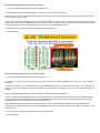
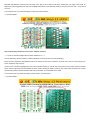
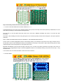
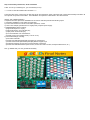
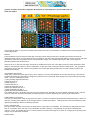
In just 5.072 of Printed Circuit Board area, (up to) 104 thru-hole components will be installed:
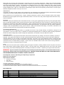
50 LEDs in 3 colors in 2 different sizes will be installed on the top side (shown at bottom center of picture for this step); and,
50 resistors in 2 values in 1 size will be mounted vertically on the back side; with (optionally):
3 power switches and 1 connector.
ABOUT THIS DOCUMENT:
This particular document ONLY presents a brief INTRO (introduction) to the groLEDs kit, followed by ONLY the ASSY (assembly)
instructions for building the kit. The (separate) User's Manual contains more information.
ABOUT THE "USER's MANUAL":
A separate document (also down-loadable from the Jameco web site) includes the following topics:
1) Assembly (installation) of the optional components
2) Control Connections for manual or automatic operations, or both.
3) How to wire multiple groLEDs kits to a single (tower) computer power supply.
4) PERFORMANCE data, including:
a) light level outputs in Lux (for);
b) light level output in Foot-Candles (for);
c) input power current levels (for);
d) for seven different color combinations;
e) all with varying input voltage levels (+3.0V to +5.5V).
5) Technical Drawings, including:
a) annotated schematic
b) Printed Circuit Board (black/white photoplot) Top Copper layer
c) Printed Circuit board (black/white photoplot) Bottom Copper Layer
d) Assembly Drawings for both the top and the bottom of the board
e) Printed Circuit Board Statistics (size of board, number and sizes of holes, trace/space dimensions, etc.)
The groLEDs kit 'overview' discuses (not repeated here) important features and functions, including:
Adjustable Brightness, Adjustable Spectrum, Directional Light Focus, Ease of Control, Safety, Low Cost, and Reliability, to name a
few.
THRU-HOLE ONLY:
The small 1.95" x 2.6" 2-layer printed circuit board uses thru-hole components only, making it a kit that can be built by any level of
expertise. All 50 LEDs are mounted on one side of the board (see the picture with this step), and all of the other components,
including optional ones, are mounted on the backside of the board. Since this is not a typical assembly process to include thru-hole
components on both sides of a printed circuit board, the instructions steps that follow walk the kit-builder through the process to
ensure reliable solder connections and no scorched LEDs (or fingers). There are four 0.2" diameter holes in each of the corners of the
groLEDs kit assembly for mounting, or hanging the fixture for usage.
GENERAL ASSEMBLY FLOW:
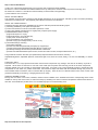
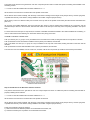
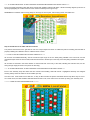
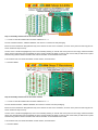
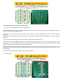
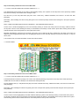
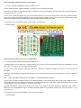
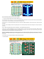
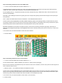
Moving from the center of the board, outwards, resistors will be installed on the backside before their corresponding LEDs will be
installed on the top side of the board, to ensure that the (hot) soldering iron does not melt the temperature sensitive dome-lenses of
the LEDs. More details are provided in the next 3 INTRO steps prior to actual assembly work.
Step 2: Introduction to the Footprints