1
US005712852A
United States Patent 1191
[11] Patent Number:
Wilson
[45]
[54] B2B DEVICE STATION ADDRESS
INITIALIZATION
STARTING WITH STORED
ADDRESS
References Cited
4,429,384
l/l984 Kaplinsky ..................... .. 370/442
4,661,902
4/1987 Hochspnmg et a1.
5,150,464
9/1992 Sidhu et a1. ....................... .. 395/2001
Kingdom
[73] Assignee: DB2 Systems Company Limited.
374,630
Jun. 24, 1994
PCT Filed:
395/800
FOREIGN PATENT DOCUMENTS
Redhill. Great Britain
[21] APPl- NO-I
Jan. 27, 1998
U.S. PATENT DOCUMENTS
[75] Inventor: Neil A. Wilson. Weybridge. United
[22]
5,712,852
Date of Patent:
[56]
‘
0537814
4/1993
European Pat. 01f.
8900717
3/1989
Nethe?ands ................... .. H04B 3/50
H04L 29/06
3900717 10/1990 Netherlands.
0 537814.411
9/1991
Netherlands ................. .. H04L 29/06
UTHER PUBLICATIONS
[86] PCT N0.:
PCT/IB94I00174
MAB 5051—Single Chip Microcontrollers; User Manual
1988. Philips Electronic Components and Materials. Chap
§ 371 Dal/B1
J m 25, 1995
s 102(6) Date: Jan. 25, 1995
ms 3 and 11
.
Primary Examiner—Wellington Chin
[87] PCT Pub‘ No" ‘NOSE/01026
PCT Pub. Date: Jan. 5, 1995
Assistant Examiner—Melissa Kay Carman
Attorney Agent, or Firm-Anne E. Barschall
[30]
[57]
Foreign Application Priority Data
Jnn.25, 1993
[EP]
European Pat. 0ff_ ____________ ,_ 93201340
ABSTRACT
[51]
Int. Cl. ................................................. .. “04L 12/403
U-S- Cl. mm....................
A single channel communication bus system has stations
which communicate with each other via the bus. Each
Station must have a unique address which is initialimd
during a System initializatkML In order to facilitate
395/281? 395/421'01
initialization. a manufacturer-determined address is stored in
[58]
Field of Search ................................ .. 370/851. 85.5.
a non-volatile memory. Search for a unique address for each
6
370185.11. 85.4. 85.9. 85.2. 85.7. 457. 447.
449. 450. 451. 452. 454. 455. 442. 489.
485; 395/200.02. 287. 200.16. 281. 200.1.
421.01; 365/189.02
station begins with the address stored in the non~volatile
memory.
7 Claims, 3 Drawing Sheets
.
SEHIAL
12
SDATQL
1
4, F
mangggcmow 51111111)
1
11111111101:
22
(011111111
11111-100111
INTERFACE
32.
/c1ncu11
" NON-VOLAHLE
111110111
33/
APPARATUS
APPARATUSJ‘F
STATION
31
INTERFACE
JCIRCUIT
1111110111 \P
23
2
42
NON-VOLATILE
115110111 \~
21
11
43
3
APPARATUS“'
"7 \
STATION
41/ 4 \
4
01111011
U.S. Patent
Jan. 27, 1998
Sheet 1 of 3
5,712,852
12
SEHIAL
SDATQL
IOIIMIéHISOATION sOATIII
, S
7
I (CIRCUIT
INTEREAOE 32w‘ I /C1RCUlT
INTERFACE
22 V
NJN-YOIATIIE
NON-YOIATIIE
MEMORY
33f
APPARATUS
‘ APPARATNsf:
31
STATION
HELD
43
3
APPARATUSJL
$ \
I
S 8
77 \
4
STATION
ACKNOWLEDGE ACKNOWLEDGE
ACKNOWLEDGE END OF
END OF
END OF
OATA
OATA
DATA
MAsTER “5AM”
sTROcTIIRE
41
STATION
ACKNCO$EEDGE
START
MESSAGE
{CIRCUIT
ACKNOWLEDGE
MOOE
B"
42
MEMORY ?
23
2
I [IIINTERFACE
NON-YOIATIIE
MEMORY \A
21
1
5
AOOREss
j
0%??? 3%?
DATA
I g I,
I ‘I g A S 3 g
,E
I
A011;
OATA
M
ACIII;
BYTE
A0111
A0111
|\-—O0E—J-I;—O0E—;I:—O0E-/I
COMMAND FIELDS
1‘
DE
FIG. 2A \
sERvI0E
AOOREss
SEBBEEEAE-T NASA/SSA
SA
TYPE FOLLOWEH
ADDRESS AOOREss
§
TA
FA
EOlzO'm "
A
US. Patent
Jan. 27, 1998
( Start: init S
Sheet 3 of3
5,712,852
1.50
1.52
15mm; SSA==MSA; MSA=='FFF'H J
NAc==0”"'5"
Send s1, MD,MSA, SSA,EF,DF
1.5%! '
,,450
1.72
FA:=FAl1
N
411.
NM == NAlI +1”"5"
L55
MSA==SSA 1/458
END
FA
L70
FIEA
ST
5,712,852
1
2
B2B DEVICE STATION ADDRESS
[NITIALIZATION STARTING WITH STORED
ADDRESS
stations will be disastrous. because if one of the two stations
is addressed by another station both stations will respond
and mostly in different ways because each station might be
a totally di?erence type of device. Also in this case no proper
initialisation will take place.
Further the Dutch patent application 8900717 discloses
The invention relates to a single channel communication
bus system. The system includes a communication bus
having a plurality of stations connected to it. The stations
that the message including the destination address also
comprises the address of the master station to be initialized.
thereby the destination station address and the master station
can communicate with one another via the communication
bus. Each station has a unique station address assigned. The
stations include an interface circuit which is adapted to call
any destination station by generating a destination station
address of said destination station. The interface circuit is
also adapted to receive an acknowledge signal which is
transmitted by the relevant destination station if the station
address of said destination station corresponds to the trans
mitted destination station address. The interface circuit of a
station is further adapted to perform an initialisation pro
gram under the control of which the interface circuit is able
to generate and transmit a plurality of different destination
station addresses in a determined sequence. Such generation
10
address are the same. In practice it has become clear that use
of the same address for the master station and the destination
station is problematic, because the receiving part of the
master station might read the destination station address and
consequently would control the transmitting part of the
master station to send an acknowledge signal to itself.
It is the object of the invention to provide a communi
cation bus system wherein the above described problems are
mitigated and address initialisation is carried in a robust
reliable noise insensitive way.
Therefore the single channel communication bus system
and transmission are discontinued upon absence of an
is characterized in that each station has a non volatile
acknowledge signal. The destination station address that is
the last that has been generated and transmitted is assigned
memory for storing the address assigned to said station.
whereby upon start of the initialisation program the genera
tion and transmission of the dilferent destination station
as the master station address to said station.
Such a single channel communication bus system is
25
of the address stored previously in said non-volatile memory
as a start address in the initialisation procedure the number
of attempts to ?nd a unique address is substantially reduced.
This reduction is even more drastic if the con?guration, i.e.
the stations connected to the bus. has not been changed.
An embodiment of the invention is characterized in that
application has been described how a new device or station
is added to the bus system. When the station has been
switched on. a software protocol in said station will initialize
the procedure to ?nd a unique address for said station. The
station address initialisation involves in fact two steps. A
?rst one is choosing an address and the second one is
verifying whether that address is unique. In order to ?nd out
whether said address is unique. the added station sends a
addresses starting with the address stored previously in said
non volatile memory. It has been found in practice that use
known ?'om the Dutch patent application No. 8900717
which has been published on Oct. 16. 1990. In said patent
35
chosen address on the bus to all other stations which are
connected to the bus system. Each station which has already
been active in the bus system checks whether the address
sent by the newly added station corresponds with its own
the station before sending a destination station address
during the initialisation program adopts a default address
which is forbidden to be used by any station operating after
initialisation in the bus system. Upon start of the initialisa
tion procedure the master station address is given a default
address. which cannot be used under normal operation (i.e.
after initialisation) by any of the other stations connected to
address or not. In the ?rst situation the station that identi?es
the address sent by the newly added device as its own. will
the bus. As a consequence any station to be initialised will
not react to its own transmitted messages. Upon determina
send back to the newly added station an acknowledge signal.
So. if the newly added station receives an acknowledge
signal it can verify that the address chosen by it previously
is not unique. As a result in a second cycle the newly added
station will choose another address di?erent from the ?rst
tion of a unique address the default address will be replaced
by the new found unique address.
The invention will further be explained in detail by use
45
chosen one and the protocol as described hereinbefore is
repeated up to the moment where no acknowledge signal
will be received by the newly added station. This means that
there is no station having this address chosen by the newly
FIGS. 2A and 2B show diagrammatically the message
50 structure as used on the communication bus.
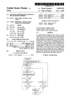
FIG. 3 shows a ?ow chart for determining the station
added station and thus this address is unique. As soon as this
address of a station in accordance with the invention.
FIG. 4 shows initialization program.
situation occurs the newly added station will adopt this
unique address as its own.
The above described station address initialisation can be
used in a D2B system. which for instance has been described
in U.S. Pat. No. 4.429.384. From the description of the D213
system in this U.S. Pat. No. 4.429.384 can be deduced that
the D2B should perform in a reliable way in a low cost and
possible noisy environment. Experience has shown that
of drawings and corresponding descriptions given
herebelow. thereby in the drawings
FIG. 1 shows diagrammatically the general structure of
a single channel communication system
55
13(1) General structure of the communication bus system.
FIG. 1 shows diagrammatically a single channel com
munication bus system. It comprises a serial communication
bus 1 consisting of two data lines 11 and 12. In this case
three stations 2. 3 and 4 are connected to this communication
bus 1. Each station 2. 3 and 4 respectively comprises an
signals on buses sometimes deteriorate which as a conse
apparatus 21. 31 and 41 respectively which is connected to
quence means that the above initialisation procedure can be
aclmowledge signal to inform the newly added station that
the data lines 11 and 12 by means of an interface circuit 22.
32. 42. As already noted, such an apparatus may be a TV
monitor, a video recorder. an audio recorder. an audio tuner.
the address send by it is not unique. but if such acknowledge
signal is deteriorated then the newly added station will adopt
65 signals from a ?rst station to a second station. Any station
said address as its own. but said address is not unique. As a
result communication between these two stations and other
may act as a master station and thereby all other stations act
as destination stations. Some stations will act as transmitters
mined. Some station on the bus system may sent an
etc. The communication bus 1 is intended to transmit control
5,712,852
3
4
of data. some act as receivers of data. Furthermore. all kinds
of mixed or alternating situations are possible. The commu
nication operations on the communication bus. which will
command ?eld. If this ?eld is the last ?eld, the communi
cation operation is terminated. Subsequently. a new com
munication operation can be started.
It is to be noted that parity bits are also transmitted in the
herein be described. are performed by the interface circuits
22. 32 and 42. A so-called microcontroller MAB 5051
di?erent ?elds so as to protect the information from trans
extensively described in chapter 3 of Single Chip Micro
controllers; User Manual 1988. Philips Electronic Compo
mission errors.
nents and Materials, for example. be used as an interface
In FIG. 2B the general structure of a station address is
shown. It comprises a service address SA. a type address TA
and a follower address FA. The service address SA
E(3) The station address.
circuit. To be able to distinguish the dilferent stations. each
interface circuit has a programmable, non volatile memory
23. 33. 43 in which a station address is stored A typical
comprises. for example four bits and can thus distinguish
sixteen services. for example an audio-video service. a
station address comprises twelve bits.
13(2) The message structure.
washing service. a cooking/baking service etc. The type
address TA comprises. for example ?ve bits so that thirty
The general structure of a message structure on an
two stations can be distinguished within one service. For
information level. which structure is extensively described
in Chapter 11 of the User Manual pointed out hereabove is
example. within the washing service a distinction can be
made between a washing machine. a drier. a dish washer.
etc. and within tile audio-video service a distinction can be
denoted in FIG. 2A. Such a message structure starts with a
start bit ST. It is followed by a mode ?eld MO in which a
number of so-called mode indication bits is transmitted. A
typical number of mode indication bits is three. They
made between a TV-set. a TV-monitor. a tuner. a video
20
indicate the rate at which the following information will be
transmitted. In fact. a limited number of standardized trans
mitter frequencies has been de?ned. This mode ?eld is
followed by a master station address ?eld MSA. In this ?eld
the twelve-bit master station address is transmitted from the 25
station wishing to transmit information to a destination
station. The twelve-bit destination station address is subse
quently transmitted in the destination station address ?eld
SSA. If a station recognizes the destination station address.
it uansmits an acknowledge code in an acknowledge code
?eld ACI. If this acknowledge code is not received. it means
that the said destination station is not present or does not
function or that the destination station address is received in
a mutilated. non-recognizable form by the destination sta
recorder. etc.
It will often occur in practice that the user has a number
of apparatuses of the same type. for example. two or more
video recorders. The follower address FA enables him to
distinguish between these apparatuses of the same type. This
follower address comprises. for example three bits so that
eight apparatuses of the same type can be distinguished.
E(4) The initialisation.
As already noted in the foregoing section. a station
address comprises a service address SA. a type address TA
and a follower address FA. Service address SA and type
address TA have been assigned by manufacturers and in
practice the manufacturer programs them in the station
address memory (23.33.43) of the interface circuit 22. 32.
42. In practice. the follower address FA will be set to zero
u'on. In these cases the communication may be discontinued 35 (or to 111) by the rmnufacturer and programming of the
follower address FA will be done in use and thus does not
each time after the acknowledge code ?eld. If the destination
take place until after the relevant apparatus has been con
station has transmitted an acknowledge code. the master
nected to the communication bus 1 by means of the interface
station transmits a control code of. for example four bits in
circuit. To this end this interface circuit has an initialisation
a control ?eld CF. After reception of this control code. the
program which comprises. for example the steps shown in
destination station again transmits an acknowledge code in
an acknowledge code ?eld ACII. Ifthis second acknowledge
code is not received by the master station. the communica
tion may be discontinued. If the master station has received
this second acknowledge code. a data ?eld DF will be sent.
In this data ?eld the master DF station transmits data to the 45
destination station. or vice versa. The data ?eld DF com
prises one single or a plurality of command ?elds DCF. Each
command ?eld comprises one or more data bytes DB which
represents the actual information. an EOD ?eld (end-of
data) the end of the data byte(s) of a cormnand ?eld and/or
indicating whether a further command ?eld DU? 11. DCF ]]1
follows this command ?eld DCF I and an acknowledge code
?eld ACHI in which the destination station indicates that the
information has been received correctly. If no acknowledge
code ACE] is received. this may mean that i) the actual
FIG. 3 and which is performed as soon as the apparatus is
switched on. More particularly after start of the initialisation
STAKl‘zlNII‘ in step 50 the present follower address PA is
used to set a test value TST in a second step S2 (TST:=FA).
Further in said second step 52 the destination station address
SSA is made equal to the present master station address
MSA (of which the parts SA. TA are ?xed and the part FA
is to be found). Thereafter the master station address MSA
is set to a default value e.g. “FFF’H. which means 1111 ll 11
50 1111 in hexadecimal notation. Further in a next step 54 a
counter CNT and a not-acknowledge counter NAC are set to
zero.
In a next program step 56 the counter CNT is checked
whether its value is equal or greater than 4. Subsequently in
55
information is mutilated due to transmission errors. ii) the
destination station is switched off after the transmission of
step 58 the counter CNT is increased by one. Reason for this
will be explained later on.
In the next program step 60 the start bit ST. the mode bits
because the processing of this information takes too long. In
of the mode ?eld MO subsequently the default station
address MSA and ?nally the destination station address SSA
of the destination station with which communication is
all these cases i.c. not receiving an acknowledge code AC
desired are sent. Detection of receipt of absence of an
the control code. or iii) the destination station is not capable
of receiving and buffering the data byte. for example
the master station is set to its repetitive position for sending
once again e.g. the whole message. Another possibility is to
resend upon absence of an acknowledge code ACIlI the
relevant command ?eld until the acknowledge code ACIII is
ultimately received. If this command ?eld is not the last
?eld. the transmission will be continued by sending the next
acknowledge code takes place in a step 62. If no acknowl
edge is received code in the aclmowledge code ?eld ACI (so
that ACI=0). then in a next step 64 the counter value NAC
65
is raised by 1 (NAC:=NAC+1). Subsequent step 66 tests
whether absence of an acknowledge bit has been detected
three times. If so then in a next step 68 the master station
5,712,852
5
6
address is set to the destination station address SSA includ
edge code is received in the acknowledge code ?eld ACI (so
ing the then present follower address FA. The initialisation
procedure will thereafter end in step 70.
that ACI=O). then in a next step 464 the counter value NAC
is raised by 1 (NAC:=NAC+1). In the subsequent step 466
it is tested whether absence of an acknowledge bit has been
detected three times. If so then in a next step 468 the master
station address is set to the destination station address SSA
However if in step 66 it is detected that the counter value
NAC is less thanthree the procedure starts again at step 56.
Each time the count value NAC will be increased unless in
step 62 it is detected that an acknowledge bit has been
received in the acknowledge code ?eld ACI (so thatACI=1).
including the then present follower address FA. The initiali
sation procedure will thereafter end in step 70.
However if in step 466 it is detected that the counter
the counter value CNT is tested in a step 56. If the counter
value
NAC is less than three the procedure starts again at
value CNT is less than 4 the steps 58 to 66 are performed 10
step 460. Each time the count value NAC will be increased
again. Whenever an acknowledge code occurs (ACI=1) this
unless in step 462 it is detected that an acknowledge bit has
been received in the acknowledge code ?eld ACI (so that
ACI=1). Whenever an acknowledge code occurs (ACI=1)
means that a station is connected to the communication bus
which has the same service address, type address and
follower address as the transmitting master station. When an
acknowledge code has been received enough times, the
counter value CNT will have the value of four. which means
that one of the stations has de?nitely a station address which
should not be used by this master station.
Therefore. after detection that the counter value CNT24
a step 72 is carried out. wherein the follower address FA is
increased by one. In a next step 74 it is tested whether the
follower address FA differs from the test value TST. if so
15 =1) this means that a station is connected to the communi
20
cation bus which has the same service address SA. type
address TA and follower address FA as the transmitting
master station.
Therefore. the follower address FA is increased by one.
in step 472 (FA:=FA+1). In a next step 74 it is tested whether
the follower address FA ditfers from the test value TST. if so
then the initialisation procedure is started again by setting
the counter value NAC to zero in step 454. If the test value
TST equals the follower address FA then all dilferent posi
the counter values CNT and NAC to zero in step 54. If the
test value TST equals the follower address FA then all 25 tions of the latter have been used If the follower address FA
then the initialisation procedure is started again by resetting
different positions of the latter have been used. If the
follower address FA consists of three bits then after 8 trials
with different values for FA the sta?ing value TST will be
reached due to the setting of TST equal to FA in step 52. In
such a situation the initialisation procedure is aborted (END)
in step 70 and said station cannot communicate via the bus
1.
consists of three hits then after 8 trials with di?erent values
for FA the starting value TST will be reached due to the
setting of TST equal to FA in step 452. In such a situation
the initialisation procedure is aborted (END) in step 470 and
30
said station cannot communicate via the bus 1.
Of course ditferent possibilities exist for ?nding unique
addresses for the stations (by use of majority votes). The
above given examples shall by no means limit the scope of
the invention, which apart from test values to be used or of
ei?ciency of the initialisation program does not make any
In the above example four times a message will be sent
on the bus and at maximum one failure i.e. acknowledge of
a message will be accepted for permitting use of an address 35
in?uence on the invention as such.
by an apparatus connected to the bus 1.
In the situation that a station has address setting means to
E(5) A further embodiment of the initialisation.
be controlled by the user e. g. a switch for setting the address
As already noted in the foregoing section. a station
of a VCR to VCR—1 or VCR-2 the ?ow charts as shown in
address comprises a service address SA. a type address TA
and a follower address FA. Service address SA and type
address TA have been assigned by manufacturers and in
practice the manufacturer programs them in the station
address memory (22.33.63) of the interface circuit 22. 32.
42. As said before the follower address FA will be set to zero
(or to 111) by the manufacturer and programming of the
follower address FA will be done in use and thus does not
take place until after the relevant apparatus has been con
nected to the communication bus 1 by means of die interface
circuit. The further embodiment of an initialisation program
comprises. for example the steps shown in FIG. 4. which are
performed as soon as the apparatus is switched on. More
particularly after start of the initialisation STARI‘rINIT in
step 450 the present follower address FA is used to set a test
FIG. 3 and FIG. 4 can be simpli?ed substantially. The steps
72 and 74 or 472 and 474 can be dispensed with and thus the
variable item TST can be dispensed with too (see step 52 and
452). At the end in step 70 or 470 the master station address
will be the default address “FPF”. which should be signalled
45 to the user via e.g. a display. The user then can throw a
switch in order to change from one preset address of the
station (VCR-1) to the second preset address of the station
(VCR-2). If this second address is acknowledged in a
succeeding initialization procedure. which is triggered by
the user by e.g. switching power off and on again. then again
the master station address is set to the default address “FFF”.
If the user does not interfere anymore then the station
continues to operate with the default address.
I claim:
value TST in second step 452 (I‘S'I‘:=FA). Further in said
1. A single channel communication bus system compris
second step 452 the destination station address SSA is made 55
mg
equal to the present master station address MSA (of which
a. a communication bus
the parts SA. TA are ?xed and the part PA is to be found).
b. a plurality of stations connected to the communication
Thereafter the master station address MSA is set to a default
bus. which plurality of stations can communicate with
value e.g. “FFF’H. which mean 1111 1111 1111 in hexa
one another via the communication bus. each respec
decimal notation. Further in a next step 454 a not
tive one of the plurality of stations requiring a respec
acknowledge counter NAC are set to zero.
tive unique station address and including
In the next program step 460 the start bit ST. the mode
i. a respective interface circuit for
bits of the mode ?eld MO. subsequently the default station
A. calling a destination station. from amongst the
address MSA and ?nally the destination station address SSA
plurality of stations. by generating and transmit
of the destination station. with which communication is 65
ting a destination station address of said destina
desired. are sent. Detection of receipt of absence of an
tion station.
acknowledge code takes place in a step 462. If no acknowl
5,712,852
8
7
addresses comprises a ?xed part which depends on the type
B. for receiving an acknowledge signal that is trans
mitted by said destination station if the respective
unique station address of said destination station
corresponds to the transmitted destination address.
C. performing an initialisation program under the
control of which the interface circuit
of station and a variable part which comprises a ?xed
number of bits.
4. A single channel communication bus system as claimed
in claim 3. characterized in that
the ?xed number of bits is three and
in the initialisation program. after each generation and
transmission of one of the plurality of di?erent desti
at. generates and transmits at least one of a
plurality of di?’erent destination addresses
according to a predetermined sequence. start
ing from a start value
10
[5. discontinues said generation and transmission
of the at least one of the plurality of different
destination station addresses. upon absence of
an acknowledge signal,
7. assigns. as the respective unique station
to create a next one of the plurality of different desti
15
address of the respective one of the plurality of
stations. a last one of at least one of the
plurality of ditferent destination station
addresses. which is the last that was generated
and transmitted. and
5. stores the respective unique station address in
20
a non-volatile fashion for use as a next start
value in a future initialisation. and
ii. a respective non volatile memory for storing the start
value and next start value as the respective unique
address of the respective one of the plurality of
stations. such that upon start of the initialisation
program. the generation and transmission of the at
least one of the plurality of di?ierent destination
station addresses starts with the start value without
added bits.
2. A single channel communication bus system as claimed
in claim 1. wherein at least one of the plurality of stations.
before transmitting the at least one of the plurality of
ditferent destination station addresses in the initialisation
nation station addresses. when such generation and
transmission is acknowledged by another station on the
bus system. the variable part is incremented by one and
25
30
nation station addresses. and
initialisation is aborted upon generation and transmission
and acknowledgment of all possible eight addresses in
the variable part.
5. A single channel communication bus system as claimed
in claim 2. wherein each of the plurality of destination
addresses comprises a ?xed part which depends on the type
of station and a variable part which comprises a ?xed
number of bits.
6. The system of claim 1 wherein communication along
the single channel bus is according to a DZB protocol.
7. A single channel communication bus system as claimed
in claim 5. characterized in that
the ?xed number of bits is three and
in the initialisation program. after each generation and
transmission of one of the plurality of di?erent desti
nation station addresses. when such generation and
transmission is acknowledged by another station on the
bus system. the variable part is incremented by one to
35
create a next one of the plurality of di?’erent destination
station addresses. and
program. adopts a default address that is forbidden to be
initialisation is aborted upon generation and transmission
used by any station except during initialisation in the bus
and acknowledgment of all possible eight addresses in
the variable part.
system.
‘
3. A single channel communication bus system as claimed
in claim 1. wherein each of the plurality of destination
*****