1
‘
‘
1130056755701
‘
‘
United States Patent [19]
[11]
Patent Number:
5,675,571
Wilson
[45]
Date of Patent:
Oct. 7, 1997
[54]
DZB DIVICE ADDRESS INITIALIZATION BY
USE OF DEFAULT ADDRESS
[75] Inventor:
4.661902
Neil A. Wilson. Weybridge. United
4/1987 Hochsprung et a1. ................ .. 364/200
8/1987 Sidhu a a1. .................... .. 370/92
4,689,786
5,187,703
211993 Nakatani etal. .
5,422,884
6/1995
Giiertz
. . .. . ... . . . . . . .
. 370/851
. . . ..
370/92
Kingdom
FOREIGN PATENT DOCUMENTS
[73] Assignee: D2B Systems Company Limited.
Redhill Surry. United Kingdom
[21] Appl. No.:
382,058
[22] PCT Filed:
Jun. 24, 1994
[86] PCT No.:
PCT/[B94/00173
§371 Date:
4/1993
European Pat. Off. .
8900717
3/1989
Netherlands .
Primary Examiner—D0uglas W. Olms
Assistant Examiner-Chau T. Nguyen
Attorney, Agent, or Firm—Anne E. Barschall
Mar. 13, 1995
[57]
§ 102(e) Date: Mar. 13, 1995
[87]
0537814
ABSTRACT
PCT Pub. No.: WO95/01025
In a single channel communication bus system. e.g. DZB.
PCI‘ Pub. Date: Jan. 5, 1995
at the same time. These devices start out with the same
sometimes two devices of the same type must be initialized
[30]
address installed by the manufacturer. The installed address
Foreign Application Priority Data
Jun. 25, 1993
[EP]
European Pat. O?‘.
includes follower bits which can be changed to account for
93201838
the presence of other devices. During initialization. all
[51]
Int. Cl.‘5 ........................... .. H04L 12/40; H04L 29/06
devices are set to a dummy address and the installed address
[52]
[58]
US. Cl. .......................................... .. 370/85.1; 370/475
Field of Search ....................... .. 370/60. 85.1. 85.11.
370/853. 85.2. 92. 94.1; 340/825.07. 825.52.
825.54; 395/824. 829; 348/721
[56]
References Cited
U.S. PATENT DOCUMENTS
4,429,384
H1984 Kaplinsky ............................ .. 370/851
is stored. Each station then looks for devices having its own
installed address. If. after 3 tries. none is found then the
stored address is used. If other devices having the installed
address are found the follower bits can be changed. The
station iterates until all possible follower bits are exhausted.
In this way the stations of the same type have an improved
likelihood of being initialized with distinct addresses.
25 Claims, 3 Drawing Sheets
US. Patent
Oct. 7, 1997
Sheet 1 0f 3
SDAT(2)
+
SDAT(T)
22
5,675,571
T
T
A
T
TNTEREADE
32 TNTERPADE
AAE/A/A
/
T“
42—’TNTERTADE
(RAE/AA?
AAA/{Pf
23 \Ii///
33 “ ////'
43 ‘~»*///
APPARATDS
r2 TDDE
21 AATTTAETZED
APPARATUS
31/ TDDE
TNTTTAETZED
APPARATUS
41/ TDRE
TNTTTADZED
if
f
2
}l
f
3
4
ACKNOWLEDGE
ACKNOWLEDGE
SA ACKNOWLEDGE DATA
MODE
DESTATATADN
00mm
STATTDTA
MASTER
END OF
START K WON ADDRESS
CONTROL
W
31; JADDRFSS K
/_/'
MESSAGE
STR U0‘*DRE
ST M0
MSA
DATA
SsA
A01DPADIDDDEDDADTTDDEDDAD111DDEDDAD1T1
11_ DCF
DDT :4 DCFJI
"r
DF
FIG. 2a
SERvTDE
ADDRESS
TYPE
ADDRESS
FOLLOWER
ADDRESS
A
‘\ 1
MSA/SSA
1
1
SA
1
I
1
I\\ 1
1
1
TA
1
FA
l
HG. 2b
1 /
l
*1
US. Patent
Oct. 7, 1997
Sheet 2 0f 3
@S“
5,675,571
52
TST I = FA ; SSA : =MSA; MSA := "FFP'H
M
r
em :=NAC ;=0
" 54
56
Y
N
l
SEND : ST; M0; MSA; SSA; CF; DF
“CD
O
/>-62
Y
,
N
NAC1=NAC+1
¢
£2
FA:=FA+1
/-’64
66
Y
N
‘
MSA:= SSA -/
FIG. 3
U.S. Patent
0a. 7, 1997
5,675,571
Sheet 3 0f 3
450
START: INIT
452
I
TST : = FA ; SSA: = MSA ; MSA :: "FFF"H
f
SEND ST, M0, MSA. SSA, CF, DF
j 460
472
462
Y
K
FA : =FA+1
N
NAC := NAC +1
/'/
466
Y
468
MSA:= SSA 5/
464
N
FA = TST?
74
5,675,571
1
2
DZB DIVICE ADDRESS INITIALIZATION BY
USE OF DEFAULT ADDRESS
signal is deteriorated then the newly added station will adopt
the address as its own. but the address is not unique. As a
BACKGROUND OF THE INVENTION
result communication between these two stations and with
out other stations will be disastrous. because if one of the
1. Field of the Invention
The invention relates to a single channel communication
bus system. The system include a communication bus hav
ing a plurality of stations connected thereto. which can
communicate with one another via the communication bus
and to each other. A unique station address is assigned to
each station. The stations include an interface circuit which
two stations is addressed by another station both stations
will respond and mostly in different ways because each
station might be a total difference type of device. Also in this
case no proper initialisation will take place.
Further the Dutch patent application 8900717 discloses
10
is adapted to call any destination station. by generating a
address are the same. In practice it has come clear that use
of the same address for the master station and the destination
destination station address of that destination station. and to
receive an acknowledge signal. The acknowledge signal is
transmitted by the relevant destination station if the station
address of said destination station corresponds to the trans
mitted destination station address. The interface circuit of a
station is further adapted to perform an initialisation pro
gram. Under the control of the initialisation program. the
15
consequently would control the transmitting part of the
master station to send an acknowledge signal to itself.
SUMMARY OF THE INVENTION
25
30
application describes how a new device or station is added
to the bus system. Once the station has been switched on.
a-software protocol in said station will initialize the proce
dure to ?nd a unique address for said station. The station
address initialisation involves in fact two steps. a ?rst one is
choosing an address and the second one is verifying whether
said address is unique. In order to ?nd out whether said
address is unique. the added station sends a chosen address
35
It is the object of the invention to provide a communica
tion bus system wherein the above described problems are
mitigated and address initialisation is carried in a robust
reliable noise insensitive way.
It is a further object of the invention to provide a com
munication system. wherein communication between sta
tions is still possible even in the situation that the initiali
sation process does not result in finding a unique address for
the station to be initialized.
An embodiment of the invention is characterized in that
the station, before sending a destination station address
during the initialization program. adopts a default address.
The default address can be set by the manufacturer of the
station. so that if a small communication system is used the
default address will be the unique address for the greater part
of initialisations. Upon start of the initialisation procedure
the master station address is given a default address. which
may not be used under normal operation (i.e. after
initialisation) by any of the other stations connected to the
on the bus to all other stations which are connected to said
bus system. Each station which has already been active in
said bus system checks whether the address sent by the
newly added station corresponds with its own address or not.
In the ?rst situation the station. which identi?es the address
sent by the newly added device as its own. will send back to
the newly added station an acknowledge signal. So. if the
newly added station receives an acknowledge signal. it can
station is problematic. because the receiving part of the
master station might read the destination station address and
interface circuit is able to generate and transmit a destination
station address more than one time. Such generation and
transmission are discontinued upon absence of acknowledge
signal. The destination station address which has been
generated and transmitted is assigned as the master station
address to said station.
2. Related Art
Such a single channel communication bus system is
known from the Dutch patent application No. 8900717
which has been published on Oct. 16. 1990. That patent
that the message including the destination address also
comprises the address of the master station to be initialized.
thereby the destination station address and the master station
bus. As a consequence any station to be initialised will not
react to its own transmitted messages. Upon determination
of a unique address the default address will be replaced by
the new found unique address.
45
In a further embodiment of the invention the single
channel communication bus is characterized in that the
verify that the address chosen by it previously is not unique.
station upon receipt of acknowledgement upon transmission
As a result. in a second cycle, the newly added station will
choose another address different from the ?rst chosen one
of its station address dm-ing initialization aborts the initial
ization procedure and adopts the default address as its own
and the protocol as described hereinbefore will be repeated
up to the moment where no acknowledge signal is received
by the newly added station. This means no station already
has this address chosen by the newly added station and thus
50
unique address.
this address is unique. As soon as this situation occurs the
In accordance with this embodiment the station. which
adopted the default address. as its own unique address is still
capable of communicating with other stations instead of
being switched off due to the fact that there was no speci?c
newly added station will adopt this unique address as its
55 address available. In the situation. where an address of a
own.
station e.g. a VCR can be set by hand by the user to one of
The above described station address initialisation can be
used in a DZB system. which for instance has been described
two unique addresses (VCRl and VCRZ). it may happen that
in U.S. Pat. No. 4.429.384. From the description of the DZB
system in this US. Pat. No. 4.429.384 can be deduced that
the DZB should perform in a reliable way in a low cost and
possible noisy environment. Experience has shown that
signals on buses are sometimes deteriorated which as a
consequence means that the above initialisation procedure
can be ruined. Some station on the bus system may send an 65
acknowledge signal to inform the newly added station that
the address send by it is not unique. but if such acknowledge
two stations unavoidably end up with the same address
(VCRI or VCR2) if three like kind stations are present in the
system. Now. by use of the default address. the performance
of the other two VCR‘s is not affected. whilst the third VCR
still can be part of the system.
In another embodiment of the invention. the single chan
nel communication system is characterized in that upon start
of the initialization program with a ?rst address. which is
acknowledged. the interface under control of the initializa
tion program is capable of transmitting and generating a
5,675,571
3
4
plurality of different destination station addresses in a pre
nents and Materials. for example. may be used as an
determined sequence. Such generation and transmission is
discontinued upon absence of the acknowledge signal. The
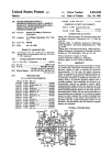
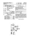
interface circuit. To be able to distinguish the different
stations. each interface circuit has a programmable. non
volatile memory 23. 33. 43 in which a station address is
stored A typical station address comprises twelve bits.
E(2) The message structure.
destination station address. which is the last that has been
transmitted is assigned as the master station address to said
station upon absence of the acknowledge signal. In this
embodiment. the station fully automatically searches for a
unique address without any interference by the user. In the
situation that each and every address of the sequence of
addresses has been tested in the initialization procedure and
each of said addresses has been acknowledged then the
station adopts the default address as its own unique address
and thus is then still able to communicate.
Another embodiment of the invention is characterized in
that the default address is forbidden to be used by any station
operating after initialisation in the bus system
A further embodiment in accordance with the invention is
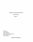
The general message structure on an information level.
which structure is extensively described in Chapter 11 of the
User Manual pointed out above. is denoted in FIG. 2A. Such
a message structure starts with a start bit ST. It is followed
by a mode ?eld MO in which a number of so-called mode
indication bits is transmitted. A typical number of mode
indication bits is three. They indicate the rate at which the
following information will be transmitted. In fact. a limited
number of standardized transmitter frequencies have been
defined. This mode ?eld is followed by a master station
address ?eld MSA. In this ?eld the twelve-bit master station
address is transmitted from the station wishing to transmit
characterized in that each station has a non volatile memory
for storing the address assigned to said station. whereby
upon start of the initialisation program the generation and
20 information to a destination station. The twelve-bit destina
tion station address is subsequently transmitted in the des
tination station address field SSA. If a station recognizes the
destination station address. it transmits an acknowledge
code in an acknowledge code ?eld ACI If this acknowledge
transmission of the di?erent destination station addresses is
starting by the address stored previously in said non volatile
memory. It has been found in practice that. by use of the
address stored previously in said non-volatile memory as a
start address in the initialization procedure. the number of
attempts to ?nd a unique address is substantially reduced.
25
station address is received in a mutilated. non-recognizable
form by the destination station. In these cases. the commu
This reduction is even more drastic if the con?guration. i.e.
the-stations connected to the bus. has not been changed.
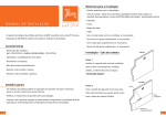
BRIEF DESCRIPTION OF THE FIGURES
nication may be discontinued after the acknowledge code
30
The invention will further be explained in detail by use of
drawings and corresponding descriptions given herebelow.
FIG. 1 shows diagrammatically the general structure of a
single channel communication system.
station. the communication may be discontinued. If the
master station has received this second acknowledge code.
FIG. 2A and FIG. 2B shows diagrammatically the mes
a data ?eld DF will be sent. In this data ?eld the master DF
station transmits data to the destination station. or vice versa.
sage structure as used on the communication bus.
DETAILED DESCRIPTION OF THE
PREFERRED EMBODIMENTS
The data ?eld DF comprises one single or a plurality of
command ?elds DCF. Each command ?eld comprises one or
more data bytes DB which represents the actual information.
an EOD ?eld (end-of-data) the end of the data byte(s) of a
command ?eld and/or indicating whether a further command
45 ?eld DCF II. DCF Ill follows this command ?eld DCF I and
an acknowledge code ?eld ACIII in which the destination
station indicates that the information has been received
correctly. If no acknowledge code ACIII is received. this
8(1) General structure of the communication bus system.
FIGS. 1 shows diagrammatically a single channel com
mnnication bus system. It comprises a serial communication
bus 1 consisting of two data lines 11 and 12. In this case
three stations 2. 3 and 4 are connected to this communication
bus 1. Each station 2. 3 and 4 respectively comprises an
apparatus 21. 31 and 41 respectively which is connected to
the data lines 11 and 12 by means of an interface circuit 22.
32. 42. As already noted. such an apparatus may be a TV
monitor. a video recorder. an audio recorder. an audio tuner.
etc. The communication bus 1 is intended to transmit control
signals from a ?rst station to a second station. Any station
may act as a master station and thereby all other stations act
as destination stations. Some stations will act as transmitters
of data. some act as receivers of data. Furthermore. all kinds
of mixed or alternating situations are possible. The commu
nication operations on the communication bus. which will
herein be described. are performed by the interface circuits
22. 32 and 42. A so-called rnicrocontroller MAB 5051
extensively described in chapter 3 of Single Chip Micro
controllers; User Manual 1988. Philips Electronic Compo
?eld. If the destination station has transmitted an acknowl
edge code. the mastm' station transmits a control code of. for
example four bits in a control ?eld CF. After reception of this
control code. the destination station again transmits an
aclmowledge code in an acknowledge code ?eld ACII. If this
second acknowledge code is not received by the master
thereby in the drawings
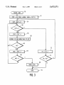
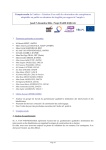
FIG. 3 shows a ?ow chart for determining the station
address of a station in accordance with the invention.
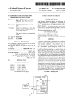
FIG. 4 shows ?ow chart of a further embodiment of an
initialisation program
code is not received. it means that the destination station is
not present or does not function or that the destination
may mean that i) the actual information is mutilated due to
50
transmission errors. ii) the destination station is switched off
after the transmission of the control code. or iii) the desti
nation station is not capable of receiving and buffering the
data byte. for example because the processing of this infor
mation takes too long. In all these cases i.e. not receiving an
acknowledge code AC the master station is set to its repeat
mode for sending once again e.g. the whole message.
Another possibility is to resend upon absence of an acknowl
edge code ACIII the relevant command ?eld frequently until
the acknowledge code ACIH is ultimately received. If this
command ?eld is not the last ?eld. the transmission will be
continued by sending the next command ?eld. If this ?eld is
the last ?eld. the communication operation is terminated.
Subsequently. a new communication operation can be
started.
It is to be noted that a number of parity bits is also
transmitted in the different ?elds so as to protect the infor
mation from transmission errors.
5,675,571
5
6
13(3) The station address.
step 62 it is detected that an acknowledge bit has been
In FIG. 2B the general structure of a station address is
shown. It comprises a service address SA. a type address TA
and a follower address FA. The service address SA
received in the acknowledge code ?eld ACI (so that ACI=1).
follower address comprises. for example three bits so that
eight apparatuses of the same type can be distinguished.
H4) The initialization.
As already noted in the foregoing section. a station
test value TST equals the follower address FA then all
different positions of the latter have been used. If the
follower address FA consists of three bits then after 8 trials
with different values for FA the starting value TST will be
reached due to the setting of TST equal to FA in step 52. In
such a situation the initialization procedure is aborted (END)
in step 70 and said station cannot communicate via the bus
1.
the counter value CNT is tested in a step 56. If the counter
vale CNT is less than 4 the steps 58 to 66 are performed
comprises. for example four bits and can thus distinguish
again. Whenever an acknowledge code occurs (ACI=1) this
sixteen services. for example an audio-video service. a
means that a station is connected to the communication bus
washing service. a cooking/baking service etc. The type
which has the same service address. type address and
address TA comprises. for example ?ve bits so that thirty
follower address as the transmitting master station. As soon
two stations can be distinguished within one service. For
as those times an acknowledge code has been received. the
example. within the washing service a distinction can be 10 counter value CNT will have the value of four. which means
made between a washing machine. a drier. a dish washer.
that one of the stations has de?nitely a station address which
etc. and within the audio-video service a distinction can be
should not be used by this master station.
made between a TV-set. a TV-monitor. a tuner. a video
Therefore. after detection that the counter value CNT§4
recorder. etc.
a step 72 is carried out. wherein the follower address FA is
It will often occur in practice that the user has a number
increased by one. In a next step 74 it is tested whether the
of apparatuses of the same type. for example. two or more
follower address FA differs from the test value TST. if so
video recorders. The follower address FA enables him to
then the initialisation procedure is started again by resetting
distinguish between these apparatuses of the same type. This
the counter values CNT and NAC to zero in step 54. If the
address comprises a service address SA. a type address TA
and a follower address FA. Service address SA and type
address TA have been assigned by manufacturers and in
practice the manufacturer programs them in the station
address memory (22.33.43) of the interface circuit 22. 32.
25
42. In practice. the follower address FA will be set to zero
In the above example four times a message will be sent on
the bus and at maximum one failure i.e. acknowledge of a
(or to III) by the manufacturer and programming of the
message will be accepted for permitting use of an address by
follower address FA will be done in use and thus does not 30 an apparatus connected to the bus 1.
take place until after the relevant apparatus has been con
E(5) A further embodiment of the initialisation.
nected to the communication bus 1 by means of the interface
As already noted in the foregoing section. a station
circuit. To this end this interface circuit has an initialisation
address comprises a service address SA. a type address TA
program which comprises. for example the steps shown in
and a follower address FA. Service address SA and type
FIG. 3 and which is performed as soon as the apparatus is 35 address TA have been assigned by manufacturers and in
switched on. More particularly after start of the initialisation
practice the manufacturer programs them in the station
STARI‘zINlT in step 50 the present follower address PA is
used to set a test value TST in second step 52 (TST:=FA).
Further in said second step 52 the destination station address
SSA is made equal to the present master station address
MSA (of which the parts SA. TA are ?xed and the part FA
is to be found). Thereafter the master station address MSA
address memory (22.33.63) of the interface circuit 22. 32.
42. As said before the follower address FA will be set to zero
(or to 111) by the manufacturer and programming of the
follower address FA will be done in use and thus does not
take place until after the relevant apparatus has been con
nected to the communication bus 1 by means of the interface
is set to a default value e.g. “FFF’H. which means 1111 1111
circuit. The further embodiment of an initialisation program
1111 in hexadecimal notation. Further in a next step 54 a
comprises. for example the steps shown in FIG. 4. which are
counter CNT and a not-acknowledge counter NAC are set to 45 performed as soon as the apparatus is switched on. More
particularly after start of the initialization STARTzlNlT in
zero.
In a next program step 56 the counter CNT is checked as
step 450 the present follower address FA is used to set a test
to whether its value is equal or greater than 4. Subsequently
in step 58 the counter CNT is increased by one. The reason
for this will be explained later on.
In the next program step 60. the start bit ST. the mode bits
of the mode ?eld MO subsequently the default station
address MSA and ?nally the destination station address SSA
of the destination station with which communication is
value TST in second step 452 TST:=FA). Fhrther in said
second step 452 the destination station address SSA is made
equal to the present master station address MSA (of which
the parts SA. TA are ?xed and the part FA is to be found).
desired are sent. Detection of lack of receipt of an acknowl
50
Thereafter the master station address MSA is set to a default
value e.g. “FFF’H. which means 1111 1111 1111 in hexa
decimal notation. Further in a next step 454 a not
acknowledge counter NAC are set to zero.
edge code takes place in a step 62. If no aclmowledge is
In the next program step 460 the start bit ST. the mode bits
received. this is coded in the acknowledge code ?eld ACI (so
of the mode ?eld MO. subsequently the default station
address MSA and ?nally the destination station address SSA
of the destination station. with which communication is
desired. are sent. Detection of receipt of absence of an
acknowledge code takes place in a step 462. If no acknowl
edge is received code in the acknowledge code ?eld ACI (so
that ACI=0). then in a next step 464 the counter value NAC
that ACI=0 ). Then in a next step 64 the counter value NAC
is raised by 1 (NAC:=NAC+1). In the subsequent step 66. it
is tested whether absence of an acknowledge bit has been
detected three times. If so then in a next step 68 the master
station address is set to the destination station address SSA
including the then present follower address FA. The initiali
sation procedure will thereafter end in step 70.
However if in step 66 it is detected that the counter value
NAC is less than three the procedure starts again at step 56.
Each time the count value NAC will be increased unless in
is raised by 1(NAC:=NAC+1). In the subsequent step 466 it
is tested whether three times absence of an acknowledge bit
has been detected. If so then in a next step 468 the master
station address is set to the destination station address SSA
5.675.571
8
7
being assigned as a master station address for the
including the then present follower address FA. The initiali
sation procedure will thereafter end in step 70.
However if in step 466 it is detected that the counter value
NAC is less than three the procedure starts again at step 460.
Each time the count value NAC will be increased unless in
step 462 it is detected that an acknowledge bit has been
respective station.
5
characterized in that each station. before sending a des
tination station address during the initialization
program. adopts a default address.
2. A single channel communication bus as claimed in
received in the acknowledge code ?eld ACI (so that ACI=1).
claim 1. characterized that each station. upon receipt of
acknowledgement upon transmission of the destination sta
tion address during initialization. aborts the initialization
Whenever an acknowledge code occurs (ACI=1) this means
that a station is connected to the communication bus which
has the same service address SA. type address TA and
follower address FA as the transmitting mastm' station.
program and adopts the default address as its own unique
address.
3. A single channel communication bus as claimed in
Therefore. the follower address FA is increased by one. in
step 472 (FA:=FA+1). In a next step 74 it is tested whether
the follower address FA differs from the test value TST. if so
claim 1. characterized in that
upon start of the initialization program with a ?rst
then the initialization procedure is started again by setting
address. which is acknowledged. the interface under
the counter value NAC to zero in step 454. If the test value
control of the initialization program transmits and
generates a plurality of different destination station
addresses in a predetermined sequence. said generation
and transmission being discontinued upon absence of
TST equals the follower address FA then all different posi
tions of the latter have been used If the follower address FA
consists of three bits then after 8 trials with different values
for PA the starting value TST will be reached due to the
setting of TST equal to FA in step 452. In such a situation
the initialisation procedure is aborted (END) in step 470 and
said station cannot communicate via the bus 1.
the acknowledge signal and the destination station
20
station upon absence of the acknowledge signal.
Of course different possibilities exist for ?nding unique
addresses for the stations (by use of majority votes). The
above given examples shall by no means limit the scope of
25
the invention. which apart from test values to be used or of
e?iciency of the initialisation program does not make any
in?uence on the invention as such.
In the situation that a station has address setting means to
of a VCR to VCR-1 or VCR-2 the ?ow charts as shown in
FIG. 3 and FIG. 4 can be simpli?ed substantially. The steps
72 and 74 or 472 and 474 can be dispensed with and thus the
variable item TST can be dispensed with too (see step 52 and
452). At the end in step 70 or 470 tile master station address
will be the default address “FFF‘. which should be signalled
to the user via e.g. a display. The user then can throw a
switch in order to change from one preset address of the
station (VCR-1) to the second preset address of the station
(V CR-2). If this second address is acknowledged in a
succeeding initialization procedure. which is triggered by
the user by e.g. switching power off and on again. then again
If
thethe
master
userstation
does address
not interfere
is set toanymore.
the defaultthen
address
the station
45
initialization in the bus system.
1. A single channel communication bus system compris
ing a communication bus having a plurality of stations
connected thereto. which stations can communicate with one SO
another via the communication bus. to each of which sta
tions a unique station address is to be assigned. each of said
respective stations comprising a respective interface circuit
for
station address for that destination stations.
receiving an acknowledge signal that is transmitted by
5. A single channel communication bus system as claimed
in claim 1. characterized in that the address generated and
transmitted in the initialisation program comprises a ?xed
part which depends on the type of station. and a variable part
which comprises a ?xed number of bits.
6. A single channel communication bus system as claimed
in claim 5. characterized in that after each generation and
transmission of destination station address which is
acknowledge by another station on the bus system is incre
mented by one for some subsequently being transmitted on
the communication bus and that initialisation is aborted
upon generation and transmission and acknowledgment of
all possible addresses available under the fixed number of
bits in the variable part of the potential station address.
7. A single channel communication bus as claimed in
claim 1. characterized in that the default address is is not
normally expected to be used by any station operating after
I claim:
calling any destination station by generating a destination
4. A single channel communication bus system as claimed
in claim 1. characterized in that each station has a non
volatile memory for storing the address assigned to said
station. whereby upon start of the initialisation program the
generation and transmission of the di?erent destination
station addresses is starting by the address stored previously
in said non volatile memory.
be controlled by the user e.q. a switch for setting the address
continues to operate with the default address.
address. which is the last that has been transmitted
being assigned as the master station address to said
55
8. A single channel communication bus as claimed in
claim 2. characterized in that upon start of the initialization
program with a ?rst address. which is acknowledged. the
interface under control of the initialization program trans
mits and generates a plurality of different destination station
addresses in a predetermined sequence. said generation and
transmission being discontinued upon absence of the
acknowledge signal and the destination station address.
which is the last that has been transmitted being assigned as
the master station address to said station upon absence of the
that destination station. if the station address of that
aclmowledge signal.
destination station corresponds to the transmitted des
tination station address. interface circuit of a station is
9. A single channel communication bus system as claimed
in claim 2. characterized in that each station has a non
further adapted to
performing an initialization program under the control of
which the interface circuit generates and transmits the
volatile memory for storing the address assigned to said
station. whereby upon start of the initialization program the
generation and transmission of the different destination
station addresses is starting by the address stored previously
destination station address more than one time.
discontinuing generating and transmitting upon absence
of the acknowledge signal. and the destination station
address which has been generated and transmitted
65 in said non volatile memory.
10. A single channel communication bus system as
claimed in claim 3. characterized in that each station has a
5,675,571
10
non volatile memory for storing the address assigned to said
station. whereby upon start of the initialization program the
generation and transmission of the di?’erent destination
normally expected to be used by any station operating after
initialization in the bus system.
20. A single channel communication bus as claimed in
claim 8. characterized in that the default address is not
station addresses is starting by the address stored previously
in said non volatile memory.
normally expected to be used by any station operating after
11. A single channel communication bus system as
claimed in claim 8. characterized in that each station has a
non volatile memory for storing the address assigned to said
station. whereby upon start of the initialization program the
generation and transmission of the different destination
station addresses is starting by the address stored previously
initialization in the bus system.
10
in said non volatile memory.
12. A single channel ‘ communication bus system as
claimed in claim 2. characterized in that the address gener
ated and transmitted in the initialization program comprises
a ?xed part which depends on the type of station. and a
variable part which comprises a ?xed number of bits.
13. A single channel communication bus system as
claimed in claim 3. characterized in that the address gener
ated and transmitted in the initialization program comprises
a ?xed part which depends on the type of station. and a
variable part which comprises a ?xed number of bits.
14. A single channel communication bus system as
IS
21. A station for use with a single channel communication
bus. the station comprising an installed master address and
an interface circuit for interfacing with said bus. which
interface circuit stores an initialization program which
includes
code for using the installed master address as a temporary
destination address and using a dummy address as a
temporary master address;
code for repeatedly sending out a message checking
whether other stations connected to the bus are using
20
the temporary destination address;
code for seeking an acknowledgement of the message;
code for. upon no receipt of an acknowledgement.
installing the temporary destination address as a master
address.
22. The station of claim 21 wherein the code for seeking
claimed in claim 8. characterized in that the address gener
ated and transmitted in the initialization program comprises 25 an acknowledgement sends the message three times and
only concludes that there is no acknowledgement after those
a ?xed part which depends on the type of station. and a
variable part which comprises a ?xed number of bits.
15. A single channel communication bus system as
claimed in claim 12. characterized in that after each gen
eration and transmission of destination station address which
is acknowledge by another station on the bus system is
incremented by one for some subsequently being transmitted
on the communication bus and that initialization is aborted
upon generation and transmission and acknowledgment of
all possible addresses available under the ?xed number of
bits in the variable part of the potential station address.
16. A single channel communication bus system as
claimed in claim 13. characterized in that after each gen—
eration and transmission of destination station address which
is acknowledge by another station on the bus system is
incremented by one for some subsequently being transmitted
on the communication bus and that initialization is aborted
three times are over.
23. The station of claim 21 wherein the temporary desti.
nation address comprises disambiguation bits; and
30
nation address; and
35
40
normally expected to be used by any station operating after
initialization in the bus system.
19. A single channel communication bus as claimed in
claim 3. characterized in that the default address is not
ment is received; and
when the temporary destination address is reinstalled as
the master address. any altered disambiguation bits are
included in the master address.
24. The station of claim 22 wherein the temporary desti
the interface circuit further comprises
code for. upon receipt of the acknowledgement. alter
45
ing disambiguation bits of the temporary destination
address; and
code for iteratively seeking of the acknowledgement
and altering disambiguation bits until no acknowl
edgement is received; and
when the temporary destination address is reinstalled as
the master address. any altered disambiguation bits are
included in the master address.
upon generation and transmission and acknowledgment of
all possible addresses available under the ?xed number of
bits in the variable part of the potential station address.
18. A single channel communication bus as claimed in
claim 2. characterized in that the default address is not
code for iteratively seeking the acknowledgement and
altering disambiguation bits until no acknowledge
nation address comprises disambiguation bits; and
upon generation and transmission and acknowledgment of
all possible addresses available under the ?xed number of
bits in the variable part of the potential station address.
17. A single channel communication bus system as
claimed in claim 14. characterized in that after each gen
eration and transmission of destination station address which
is acknowledge by another station on the bus system is
incremented by one for some subsequently being transmitted
on the communication bus and that initialization is aborted
the interface circuit further comprises
code for. upon receipt of the acknowledgement. alta
ing the disambiguation bits of the temporary desti
25. A bus system comprising
55
a plurality of stations as claimed in claim 21; and
a single channel communication bus for allowing the
stations to communicate with each other and them
selves.