1
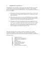
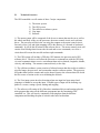
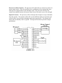
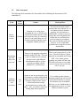
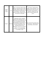
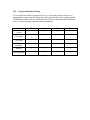
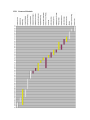
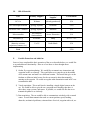
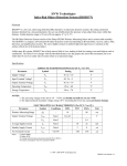
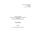
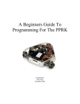
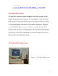
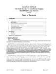
Autonomous GPS
Controlled Car
ECE 3992
Senior Design Project
Proposal
Huy Vo
Seth Thorup
Brian Bradford
Bryce McAllister
I.
Autonomous GPS -Controlled Car
The autonomous GPS-controlled car will navigate itself using GPS-defined way points.
It will be able to avoid large obstacles that might lay in its path by using a collisiondetection and avoidance system embedded in the car. A few examples of the operation of
the car are listed here:
a) The operator will give the car one specific way point to drive to. The car will
drive to that point, avoiding obstacles along the way, and stop there to await
further instructions.
b) The operator will give the car a course to travel defined by many way points.
The car will follow that course by visiting each way point in turn until it has
finished the course where it will stop to await further instruction.
c) The operator will give the car a path to travel as in the example above, but
will tell the car to continue following the path back and forth until it is told to
stop. In other words, the car will visit each way point in turn until it gets to
the last one where it will turn around and visit the points again in reverse
order, repeating this until told by the operator to stop.
Many other interesting functions might be possible as explained in the “Possible
Extensions and Add-ons” sections of this paper. This paper describes the proposed
project in more detail along with potential risks and proposed scheduling. It contains the
following sections.
II.
III.
IV.
V.
VI.
VII.
VIII.
IX.
X.
Technical Overview
Hardware of the Autonomous Car
Software of the Autonomous Car
Interfaces
Risk Assessment
Proposed Individual Tasking
Tentative Project Schedule
Bill of Materials
Possible Extensions and Add-Ons
II.
Technical Overview
The GPS-controlled car will consist of these 5 major components.
1)
2)
3)
4)
5)
The motor system
The GPS system
The collision avoidance system
User input
Software
1) The motor system will be composed of the dc servo motors that run the car as well as
the wheels and body of the car, the processor, the motor control circuit, and a software
driver. The processor will drive the car using four outputs to the motor control circuit:
forward, reverse, left, and right (stopping will be the absence of a forward or backward
command). It will do this by means of the software driver. The motor control circuit will
consist of an H-bridge that executes the forward and reverse commands, as well as a
circuit that will execute the turn left and turn right commands.
2) The GPS system will include a GPS chip, GPS antenna, the processor and a GPS
software driver. The driver will allow the processor to communicate with the GPS chip
via serial communication to receive environment data such as latitude, longitude, altitude,
velocity, and heading. The antenna connects directly to the chip.
3) The collision avoidance system consists of infrared sensors that detect objects within a
specified range, the processor, and a somewhat complex software routine. The processor
will gather data from the sensors and use the data as input to the software that will decide
the best course of action to take to avoid hitting the obstacle.
4) The User input system involves detecting when user input has been entered and
jumping to a handler to accept the input. Possible types of input will be defining way
points or a course, setting a speed, starting and stopping.
5) The software will consist of all of the above mentioned drivers and routines plus the
main program that unites all the different components into the functioning GPScontrolled car. This will involve continually collecting data from the different
components and deciding the plan of action to take based on that data.
III.
Hardware of the Autonomous Car
Car – The basic car unit (body, wheels, motors, power supply) will come from a
commercially available radio controlled car. We will use the above mentioned parts but
we will redesign and implement all of the internal circuitry. The initial car will be a Tyco
Grave Digger RC truck as shown below. After the GPS Car is functional, if we decide
we want a more powerful model we will use a different car.
Grave Digger
Motors – The DC servo motors that we will use come with the above mentioned truck.
Motor Power Supply – The Grave Digger uses a 6.0V battery pack. This power will not
be used for the internal circuitry. It will only be used to power these motors.
H-Bridge – An H-bridge circuit will be used to control the forward/reverse motor. We
will implement the bridge shown on page 474 of Embedded Microcomputer Systems.
We will use the Grave Digger’s own motor control circuit for left/right control.
GPS Receiver Chip – This will be the center of the on-board navigation system. The
GPS chip will receive signals from the GPS satellites and will communicate the
necessary information to the processor. The information that can be sent to the processor
includes the car’s latitude, longitude, height, velocity, heading, and time. All of this
information might not be needed for the basic operation of the car, but it will be useful
when we begin to add additional capabilities. We will be using Motorola’s FS Oncore
GPS chip (below) which we can get at a discount through Synergy Systems’s GPS for
Scholars program.
FS Oncore
GPS Antenna – The GPS receiver will need an antenna to accurately receive the signals
from the GPS satellites. Motorola’s Hawk GPS antenna is included in the starter kit that
we will purchase from Synergy Systems.
Microcontroller – The brains of the autonomous car will be an 8-bit RISC-architecture
processor. This will need to communicate with the GPS chip to find out the position,
heading, and speed of the car. The processor will use this information to determine the
best way to get to the desired way point. It will control the motor driver circuit to adjust
the car’s position and speed as needed. The processor will also receive information from
the infrared sensors. It will use this information to detect if an obstacle is in the current
path. If it encounters an obstacle it will avoid it by driving the car around it, or backing
up and trying an alternate path. We will be using an Atmel 8 bit AVR microcontroller,
specifically the AT90S8535.
IR Sensors – The eyes of the collision detection and avoidance system will be 3 infrared
sensors mounted on the front of the car. There will be one in the center to detect head-on
collisions and one on either side at an angle to detect obstacles, such as walls, on the
sides. We will use Sharp’s GP2D05 IR Ranger Sensors.
Input Switches and Buttons – We will need a few buttons and switches on the car to
control functionality. We will need a switch for the digital power supply, a button to
manually input GPS way points, and another button to select the operating mode of the
vehicle. Other buttons may be necessary as we add to the functionality of the car.
Digital Power Supply – The power used for the digital components of the car will be
different from the motor’s power supply. We will most likely use batteries to get the
required voltages. Both the processor and the sensors will require a voltage between 4
and 7 volts depending on the processor we use. We can use a simple voltage divider to
get the 3V source needed by the GPS chip.
Breadboard – The initial prototype of the GPS car will use a breadboard for the internal
circuitry. Once it is functioning, we might opt to use wire-wrapping or a PCB.
IV.
Software of the Autonomous Car
All of the software used by the car will be embedded in the processor’s EEPROM. The
software will include drivers to communicate with the different components, and a main
part that takes control of the car. A driver will be needed to control the GPS chip and
allow communication to take place between the GPS chip and the processor. Another
driver will control and communicate with the infrared sensors. The third driver will be
used to communicate with the motor control circuit. There will need to be collision
detection and avoidance software that checks for obstacles and reacts to them. This could
involve navigating around the object; stopping, backing up, and finding a different path;
navigating alongside a wall or building, etc. Another part of the software will
communicate with the GPS to find the current location and use that to calculate a route
that will lead to the desired location. There will also be interrupt handlers to handle
input. The main program will use all of these software components to gather the
necessary data to control the car.
V.
Interfaces
Processor to GPS – Motorola’s Oncore GPS chip uses a TTL serial communication
interface at a 9600 baud rate to send data to the processor. It can operate in either
continuous mode or polled mode. Both modes will be useful for our project. If the car is
far away from the way point it can operate in polled mode, updating it’s position every
few seconds. This would save power since the GPS and processor wouldn’t be sending
data back and forth continuously. As the car gets closer to its destination it could switch
to continuous mode in order to get more accurate positioning. Commands are sent from
the processor to request the desired information from the GPS chip.
Processor to IR Sensors – The Sharp IR Ranger Sensors use a 2-wire serial interface to
detect the presence of objects in a 10-80 cm range. The range can be set by a dial on the
back of the sensors. We will have to test different ranges on the three sensors to get
optimal performance. The sensors only take readings when requested. The protocol for
detecting an object is extremely simple. To request a reading the processor will lower the
input line, wait between 28 and 56 ms and then read the output line. A one on the output
line means there is no object within the specified range. A zero on the output line means
an object has been detected. Because the sensors use a lower voltage than the processor
we will need to use a diode to drop the voltage on the input to the sensor. The output
voltage from the sensor should be high enough for the processor to detect without
amplifying it.
Processor to Motor Control – The processor will control the car’s motors by means of a
motor control circuit. This will most likely be a combination of the circuitry that came
with the Grave Digger and our own H-bridge circuit. The processor will have four
control lines sinking current to the motor control circuit: forward, reverse, left, and right.
Input to Processor – The processor will use interrupt driven inputs to accept commands
from the operator. The operator will be able to select different modes of operation such
as fast or slow, more accurate positioning, and course-repeat mode. The operator will
also be able to manually enter way points. The input will be done by means of simple
push-buttons.
VI.
Risk Assessment
The following table summarizes the foreseeable risks of building the Autonomous GPScontrolled car.
Task
MotorControl
Circuit.
Interfacing
the GPS
chip to the
processor
Collision
Detection
and
Avoidance
Risk
Level
Nature
Back-up Plan
Medium
Because we are using a preassembled RC car, we will need to
experiment with the motors to find
out exactly how they are controlled.
Once we can control them we will
be able to build an h-bridge circuit
compatible with the processor.
We can use the motor control
circuitry that came with the car. If
we cannot get that to function
properly, we can search for a
different RC car that we know we
can get the motor information for.
Failing this we could build our
own car using dc servo motors.
We want to avoid this at all costs
however, as we would rather
spend the time giving the car more
functionality.
Low
to
None
No one in our group has experience
working with a GPS chip. This risk
is not very high however, because
the chip comes with sufficient
documentation, and we all have
experience working with the
standard TTL serial interface.
There is no back up plan if we fail
here. The whole project is based
upon the car navigating itself using
GPS. If we cannot get this
working, our project will not work.
This does not worry us very much
however because the level of this
risk is very low.
Low
to
None
Again, no one in our group has a lot
of experience working with infrared
sensors, but the protocol used here is
extremely simple and the sensors
will have more than enough
documentation to go along with
them. Also, we all have experience
writing input-driven programs.
If we cannot get this system to
function properly, the car will still
operate but it will have to operate
in an obstacle- free environment.
However, we are confident that we
can implement at least a very basic
collision avoidance system.
Digital
Power
Supply
Software
Low
This is a risk because there are three
different components that all require
a slightly different voltage level: the
microcontroller, the GPS chip, and
the IR sensors. This risk is low
because all of the voltage levels are
low and close to each other.
We can use a separate power
supply for each component. This
will most likely not be necessary,
but if so the car will still run. It
will just be a little heavier and
slower, and will consume more
power.
Medium
Although the software needed to
operate each component of the car
will not be overly complicated, each
piece will require precise detail.
Integrating all of the software into
one operational module will be a
little more complicated and will
potentially require a lot of
debugging, testing, and redesigning.
We have a lot of programming
experience, so given enough time,
we will make it work.
We can make the operation of the
car more basic. This will decrease
the difficulty of the software.
XII.
Proposed Individual Tasking
To create all of the different systems of the car we will mostly work in teams of two.
Integrating the systems into the final project will require the four of us working together.
The different systems of the car will be divided up based on individual skill and interest.
Here is a chart containing proposed tasking assignments.
Task
Motor control
system
Huy
GPS system
?
Seth
?
User input
Brian
Bryce
?
?
?
?
Collision
avoidance
?
Software
?
?
?
?
Documentation
?
?
?
?
?
VIII. Proposed Schedule
IX.
Bill of Materials
Part
Primary Supplier
Secondary
Supplier
Cost Estimate
RC Car
Walmart
(already purchased)
$30
GPS Development Board
Synergy Systems
Acroname
$150
FS Oncore User’s Manual
Synergy Systems
Motorola
$50
Microcontroller
All American
Semiconductor
Arrow Electronics
$10
IR Sensors (3)
Acroname
Sharp
$19 x 3 = $57
Miscellaneous Parts
(batteries, resistors,
capacitors, buttons, etc.)
U of U
Radio Shack
$30
Total
X.
$320
Possible Extensions and Add-Ons
Once we have completed the basic operation of the car as described above, we would like
to try and add more functionality. Here are a few ideas we have thought about
implementing.
1) On-the- fly waypoint updating: We would like to transmit new instructions and
waypoints to the car remotely. This would allow us to stop the car in the middle
of its current route and send it to a different location. This would also give us the
freedom to define an initial course for the car remotely other than manually
entering each waypoint. We could use regular radio transmission used in RC cars
to transmit the data.
2) Visual acquisition: This would involve installing a simple digital camera on the
car. We would be able to give the car a waypoint and a heading, then have it
drive there, snap a picture, and return. If possible, we would also like the car to
transmit the photo to us wirelessly.
3) Data acquisition: The car would be able to communicate wirelessly with a control
center. It could then transmit data such as current position, speed, heading,
obstacles, mechanical problems, estimated time of arrival, waypoint achieved, etc.