1
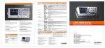
Satisfy All Your High Speed Load Simulation Needs
The PEL-2004 and PEL-2002 are multiple channel, programmable DC electronic loads with a modularized structure. The PEL-2000 Series
is designed to meet the continuing shift toward high speed operation in today's semiconductor market. As the power supply units, DCDC converters, and batteries that drive semiconductor circuits need to follow this shift, power supply design, quality inspection and
characteristic certification using high-speed performance loads have become necessary. The PEL-2000 Series includes two types of
mainframes and 4 types of load modules to accommodate users' requirements in a flexible manner. Any load module combination can
used with a mainframe to tailor a test system based on the number of channels, and the maximum load power, voltage and current of
each channel. Multiple loads can be connected in parallel to provide a higher-power load to test higher power supply outputs. This
flexibility significantly reduces the investment needed for future projects that have differed power requirements.
The PEL-2004 is a 4-slot mainframe with a master control unit to hold 4 load modules, while PEL-2002 is a 2-slot mainframe with master
control unit to hold 2 load modules. When the PEL-2004 is configured with 4 load modules rated at 350W each, the PEL-2000 series is
able to sink up to 1.4kVA of power.
For higher load capacities, mainframes can be linked together in parallel with standard MIL 20-pin connectors. A maximum of 5
mainframes, including one master and 4 slaves can be chained together to create a total load capacity of 7kW for high current and high
power applications. Using 4 dual channel load modules, the PEL-2004 is able to test 8 power supply outputs simultaneously.
The Sequence function allows each channel to change its load sink according to a predefined sequence at a rate of up to 100 s per step.
Each sequence is able to run concurrently, under the control of one clock. This is one of the most powerful features of the PEL-2000 Series
as it is able to realistically simulate a multi-output power supply load. Under Dynamic mode, the load current or load resistance pulses
between two preset levels at a pre-defined speed up to 25 s per step. This is often used as the standard test procedure to verify the
response of a power supply to quick load changes. Most remarkably, multiple load channels can be connected in parallel to run Dynamic
tests synchronously under a single clock. This Parallel Dynamic functionality gives the flexibility to perform dynamic tests for a high-power
power supply without the need of another high-power load.
The PEL-2000 Series includes a number of protection modes: Over Current Protection (OCP), Over Voltage Protection (OVP), Over Power
Protection (OPP), Reverse Voltage Protection (RVP), and Under Voltage Protection(UVP). The protection modes are useful to protect both
the load modules and the DUT(s). A buzzer can be set for when a protection setting has been tripped. When a protection mode has been
tripped, the load unit will display an alarm and stop sinking current/voltage. When a load unit is operating in CR or CV mode, the unit
may need Over Current Protection to prevent excessive current being sunk. Over Current Protection stops the load from sinking more
current than its recommended limit and prevents the load from burn-out damage. Over Voltage Protection is used to limit the amount of
voltage sunk. If the OVP trips, the PEL-Series load will stop sinking voltage. Over Power Protection is used when the input power exceeds
the specifications of the load. When OPP is tripped, the power will cease to be sunk. Reverse Voltage Protection prevents reverse voltage
damage to the PEL-2000 Series up to the specified rating. When Reverse Voltage Protection has been tripped, an alarm tone will sound
until the reverse voltage is removed. Under Voltage Protection will turn off the load when the voltage drops below a set limit.
The Go/NoGo function is available to monitor test results all the time. When a test result goes beyond a preset limit range, a "No Go"
indication will be shown on the display and a "No Go" signal can be sent out through the D-SUB interface for external device control. This
Go/NoGo function is available for CC mode, CV mode and CR mode. Under "Program" mode, 12 programs each containing 10 panelsetup memories, can be edited to create work routines for repetitive tests. After a program has been executed, the results of all test steps,
along with the Go/NoGo judgments, will be shown on the screen. For external control and system configuration, the PEL series has USB
and RS232 interfaces as standard and GPIB as an option. The LabView driver and Data Logging PC software are both supported for all
the available interfaces. Each channel has an analog control/monitoring connector on the rear panel to externally turn a load on/off and
to externally monitor load input current and voltage.
A.
AUTOMATICALLY SEQUENCE FUNCTION
(
)
(
)
Sequence - On End Load
The Sequence function allows each channel to change its load sink
according to a predefined sequence at a rate of up to 100 s per
step. Each sequence is able to run concurrently, under the control of
one clock. This is one of the most powerful features of the PEL-2000
Series as it is able to realistically simulate a multi-output power
supply load. Under Dynamic mode, the load current or load
resistance pulses between two preset levels at a pre-defined speed
up to 25 s per step. This is often used as the standard test
procedure to verify the response of a power supply to quick load changes.
The figure above shows the current waveform
of a simulation using the sequence function.
The picture above is an example of a sequence used as a load profile for a
single output switching power supply. A load profile is programmed to
simulate the current draw of a power supply load.
By using a current probe to acquire a current waveform, the PEL-2000 is able
to evaluate the performance of a power supply based on the load sequence
that is programmed. An oscilloscope is then used to display the result.
B.
MULTIPLE OPERATING MODE
C.C. ( Constant Current )
C.V. ( Constant Voltage )
In Constant Current mode, a load unit will sink the amount of current
programmed. Regardless of the voltage change, the current will stay
the same. Two selectable ranges are available for constant current
mode: High (HI) and low (LO) range. Low range has a higher
resolution for high precision measurements. If the current exceeds
the low range, high range must be used. The PEL-2000 Series offers
the maximum rated power for the low measurement range. This
unique feature enables high-resolution measurements at high
voltage only if the load current doesn't exceed the rated low range
level. Both static and dynamic modes are available for CC operation.
Static mode can be used for stability tests and Dynamic mode can
be used to test transient load performance of a power supply.
Go/NoGo is supported for both high and low ranges as well as
Static and Dynamic modes.
C.V.+C.C. ( Constant Voltage + Constant Current )
When using CV mode, a current limit can be set for CV+CC mode.
If the input voltage is greater than the preset CV limit, the channel
will operate in CV mode if the input current is less than the preset
CC limit. When the input current exceeds the current limit, the
channel will operate in CC mode.
C.
PARALLEL DYNAMIC LOADING
In Constant Voltage mode the load unit will sink current whilst
keeping the voltage constant. Under CV mode, single channel load
modules support two levels of voltage (A Value, B Value) with a
preset cut-off current limit. An A / B button is available on the load
module front panels to switch the Constant Voltage between A
Value and B Value for power supply load regulation testing. Dual
channel load modules only support A Value for CV mode. To
accommodate the response of a power supply, response rates
during voltage transitions can be set to fast or slow under static
test mode.
C.R. ( Constant Resistance )
In Constant Resistance mode the load units will linearly sink current
and voltage to match a set resistance. Two different CR values and
two different rising and falling slew rates can be set under CR Mode
for single channel load modules. Like CC mode, Constant Resistance
mode supports both dynamic and static loads. As with the other
modes, Go/No Go is also supported.
D.
FRAME LINK
FRAME CONT
1
2
FRAME CONT
1
2
Dynamic Test
Wire Connection
FRAME CONT
1
2
All the load channels in a PEL-2000 mainframe can be connected in
parallel to perform any combination of static or dynamic loading.
Under Dynamic mode, the load current or load resistance pulses
between two preset levels at a predefined speed of up to 25 s per
step. When the channels are connected in parallel, dynamic tests
are synchronously clocked. The ability to perform parallel dynamic
loading gives you the flexibility to perform dynamic tests to highpower power supplies without the need for a dedicated high power
electronic load.
The PEL-2000 Series allows multiple mainframes to be linked together
with standard MIL 20-pin connectors to provide higher power load
capacity. A maximum of 5 mainframes maximum, including one
master and 4 slaves, can be chained together to give a 7kW load
capacity for high current and high power applications
E.
RUN PROGRAM
Under "Program" mode, up to 12 programs each with 10 panel setup
memories, can be edited to create work routines for repetitive tests.
After a program has completed, the results of all test steps, including
the Go/NoGo judgments will be shown on the screen. Up to 12
programs with a total of up to 120 panel-setup memories can be
chained together to be run one after the other.
F.
G.
PROTECTION MODES
The PEL-2000 Series includes a number of protection modes: Over Current
Protection (OCP), Over Voltage Protection (OVP), Over Power Protection (OPP),
Reverse Voltage Protection (RVP), and Under Voltage Protection (UVP). The
protection modes are useful to protect both the load modules and the DUT(s).
A buzzer can be set for when a protection setting has been tripped. When a
protection mode has been tripped, the load unit will display an alarm and stop
sinking current/voltage. When a load unit is operating in CR or CV mode, the
unit may need Over Current Protection to prevent excessive current being sunk.
Over Current Protection stops the load from sinking more current than its
recommended limit and prevents the load from burn-out damage. Over Voltage
Protection is used to limit the amount of voltage sunk. If the OVP trips, the
PEL-Series load will stop sinking voltage. Over Power Protection is used when
the input power exceeds the specifications of the load. When OPP is tripped,
the power will cease to be sunk. Reverse Voltage Protection prevents reverse
voltage damage to the PEL-2000 Series up to the specified rating. When
Reverse Voltage Protection has been tripped, an alarm tone will sound until
the reverse voltage is removed. Under Voltage Protection will turn off the load
when the voltage drops below a set limit.
H.
Von VOLTAGE SETTINGS
Von Voltage is the voltage limit at which the load will start to sink
current. The Von Voltage setting is necessary for some kinds of
power supply if a heavy load is connected during load on. There are
two operation modes for Von Voltage: Latch ON and Latch OFF.
When Von Latch is set to ON, the load starts to sink current when
input voltage exceeds Von, and will continue to sink current even if
the voltage drops below the Von Voltage later. When Von Latch is
set to OFF, the load starts to sink current when input voltage
exceeds Von, but will stop sinking current when the voltage drops
below the Von voltage setting. This is to prevent the power supply
from running into oscillation when the output voltage goes below
certain level.
EXTERNAL CHANNEL CONTROL
6
5
4
3
2
1
Channel Control /
Monitoring Connectors
+15V
Load On
EXT VREF
V MON
I MON
GND
Output
External Voltage
Connection
Input
6
5
4
3
2
1
EXT VREF
GND
Twisted
Pair
External
Voltage
Output
Pin Assignment for the
Channel Control Connectors
The external voltage reference input must be between 0~10V.
Voltage and Current
Monitor Output
6
5
4
3
2
1
V MON
I MON
GND
Voltage Monitor
Current Monitor
A six-pin analog control connector is available on the rear panel to
externally turn a load on/off and to externally monitor the load input
status of each channel, including input current, input voltage, and
CC current or CV settings. The Voltage Monitor Output (VMON) and
Current Monitor Output (IMON) output the load input voltage and
load input current as a percentage of rating current/voltage. Where
0 volts = 0% rating and 10 volts = 100% load input rating voltage or
current. The voltage monitor output is across pins 1 & 3, and the
current monitor output is across pins 1 & 2. Below shows the pin
configuration of the voltage and current monitor outputs.
Load on Connection
6
5
4
3
2
1
Load On
TTL input
voltage
GND
To turn a load on, an active low voltage (0-1V) must be applied
across Load On (pin 5) and GND (pin 1), similarly an active high
voltage (4-5V) must be applied to turn a load off. The Load On
input must be TTL.
PANEL INTRODUCTION
6
1
9
2
3
7
4
5
8
1. Mainframe (Master) LCD Display
320 by 240 TFT LCD
2. Function Keys
3. System Keys
4. Mainframe Operation Keys
12
10
5. USB Device Port
11
6. Load Module Operation Keys
7. V Sense
13
8. Terminals
14
9. Selector Knob
10. Go/NoGo Output
15
11. GPIB
12. RS-232C
13. USB Device / Host Port
14. Mainframe Control Connector
15. External Channel Control 1~8
Modularized Structure
4-Slot Programmable DC Electronic Load Mainframe
The PEL-2004 is a 4-slot mainframe with a master control unit
made to hold 4 load modules, and the PEL-2002 is a 2-slot
mainframe with a master control unit made to hold 2 load
modules. The modularized structure of the PEL-2000 Series
allows any combination of mainframe and load module
(PEL-2020, PEL-2030, PEL-2040, PEL-2041) to be integrated
into a custom-tailored system.
Multiple loads within the same mainframe can be connected in
parallel to perform both static and dynamic tests. This flexibility
makes the PEL-2000 Series a very cost-effective instrument for
testing a broad range of power supply outputs.
Program & Interface
PEL-2004
2-Slot Programmable DC Electronic Load Mainframe
The PEL-2000 Series supports a total of 12 different programs
and 10 sequences to each program. With a total of up to 120
different configurations. For external control and system con
figuration, the PEL series has USB and RS-232 interfaces as
standard and GPIB as an option. The LabView driver and Data
Logging PC software are supported for all the interfaces available.
Each channel has an analog control/monitoring connector to
externally turn a load on/off and to externally monitor load
input current and voltage.
PEL-2002
SPECIFICATIONS
PEL-2020
CHANEL
RANGE
POWER
CURRENT
VOLTAGE
MIN.OPERATING VOLTAGE(DC)
PEL-2030
PEL-2040
PEL-2041
L/R
Low
100W
0~2A
1~80V
1.0V at 2A
L/R
High
100W
0~20A
1~80V
1.0V at 20A
Left
N/A
30W
0~5A
1~80V
1.0V at 5A
Right
Low
250W
0~4A
1~80V
1.0V at 4A
Right
High
250W
0~40A
1~80V
1.0V at 40A
Low
350W
0~7A
1~80V
1.0V at 7A
High
350W
0~70A
1~80V
1V at 70A
Low
350W
0~1A
2.5~500V
2.5V at 1A
High
350W
0~10A
2.5~500V
2.5V at 10A
0~2A
0.5mA
(0.1%set +
0.1%F.S.)
0~20A
5mA
(0.1%set +
0.1%F.S.)
0~5A
1.25mA
(0.1%set +
0.1%F.S.)
0~4A
1mA
(0.1%set +
0.1%F.S.)
0~40A
10mA
(0.1%set +
0.2%F.S.)
0~7A
1mA
(0.1%set +
0.1%F.S.)
0~70A
10mA
(0.1%set +
0.2%F.S.)
0~1A
0.2mA
(0.1%set +
0.1%F.S.)
0~10A
2mA
(0.1%set +
0.2%F.S.)
0.075 ~300
(100W/16V)
3.75 ~15K
(100W/80V)
12bits
300 : (0.2%set+0.1 )
15K : (0.1%set+0.02 )
With 2.5V at input
0.3 ~1.2K
(30W/16V)
15 ~60K
(30W/80V)
12bits
12K : (0.2%set+0.1 )
60K : (0.1%set+0.01 )
With 2.5V at input
0.0375 ~150
(250W/16V)
1.875 ~7.5K
(250W/80V)
12bits
150
(0.2%set+0.1 )
7.5K : (0.1%set+0.02 )
With 2.5V at input
1~80V
20mV
(0.05%set+0.1%F.S.)
1~80V
20mV
(0.05%set+0.1%F.S.)
STATIC MODE
CONSTANT CURRENT MODE
Range
Resolution
Accuracy
CONSTANT RESISTANCE MODE
Range
Resolution
Accuracy
CONSTANT VOLTAGE MODE
Range
Resolution
Accuracy
0.025 ~100
(350W/16V)
1.25 ~5K
(350W/80V)
12bits
100 : (0.2%set+0.1 )
5K : (0.1%set+0.02 )
With 2.5V at input
1.25 ~5K
(350W/125V)
50 ~200K
(350W/500V)
12bits
5K : (0.2%set+0.02 )
200K : (0.1%set+0.01 )
With 5V at input
1~80V
20mV
(0.05%set+0.1%F.S.)
2.5~500V
100mV
(0.05%set+0.1%F.S.)
0.025mS~10mS/Res:1 S
1mS ~ 30S / Res : 1mS
1 S / 1mS 100ppm
0.025mS~10mS/Res:1 S
1mS ~ 30S / Res : 1mS
1 S / 1mS 100ppm
DYNAMIC MODE
CONSTANT CURRENT MODE
T1&T2
Accuracy
0.025mS~10mS/Res:1 S 0.025mS~10mS/Res:1 S
1mS ~ 30S / Res : 1mS
1mS ~ 30S / Res : 1mS
1 S / 1mS 100ppm
1 S / 1mS 100ppm
Slew Rate( 10%set+15 S)
Slew Rate Resolution
Current
Current Resolution
Current Accuracy
0.32~80mA/ S
0.32mA/ S
0~2A
0.5mA
0.4% F.S.
3.2~800mA/ S
3.2mA/ S
0~20A
5mA
0.4% F.S.
0.8~200mA/ S
0.8mA/ S
0~5A
1.25mA
0.4%F.S.
0.64~160mA/ S
0.64mA/ S
0~4A
1mA
0.4%F.S.
6.4~1600mA/ S
6.4mA/ S
0~40A
10mA
0.4%F.S.
0.001~0.28A/ S 0.01 ~ 2.8A/ S 0.16~40mA/ S
0.001A/ S
0.01A/ S
0.16mA/ S
0~7A
0~70A
0~1A
1mA
10mA
0.2mA
0.4%F.S.
0.4%F.S.
0.4%F.S.
1.6~400mA/ S
1.6mA/ S
0~10A
2mA
0.4%F.S.
0~16V
0~80V
0~16V,0~80V
0.5mV,2.5mV
0.5mV
2.5mV
(0.05%set
(0.05%set
(0.05%set
+0.05%F.S.) +0.05%F.S.) +0.05%F.S.)
0~16V
0.5mV
(0.05%set
+0.05%F.S.)
0~80V
2.5mV
(0.05%set
+0.05%F.S.)
0~16V
0.5mV
(0.05%set
+0.05%F.S.)
0~80V
0~125V
0~500V
2.5mV
4mV
16mV
(0.05%set
(0.05%set
(0.05%set
+0.05%F.S.) +0.05%F.S.) +0.05%F.S.)
0~2A
0.0625mA
(0.1%set
+0.1%F.S.)
0~5A
0.15625mA
(0.1%set
+0.1% F.S.)
0~4A
0.125mA
(0.1%set
+0.1% F.S.)
0~40A
1.25mA
(0.1%set
+0.1% F.S.)
0~7A
0.175mA
(0.1%set
+0.1%F.S.)
0~70A
1.75mA
(0.1%set
+0.1%F.S.)
PROTECTIVE
1~102W
0.5W
1~30.6W
0.15W
1~255W
1.25W
1~357W
1.75W
1~357W
1.75W
0~20.4A
0.05A
0~5.1A
0.0125A
0~40.8A
0.1A
0~71.4A
0.175A
0~10.2A
0.025A
1~81.6V
0.2V
85
1~81.6V
0.2V
85
1~81.6V
0.2V
85
1~81.6V
0.2V
85
1~510V
1.25V
85
110W
33W
275W
385W
385W
5.5/5A
0V
15 , 0.3
4.4/4A
0V
1.875
MEASUREMENT
VOLTAGE READBACK
Range
Resolution
Accuracy
CURRENT READBACK
Range
Resolution
Accuracy
0~20A
0.625mA
(0.1%set
+0.1%F.S.)
0~1A
0.032mA
(0.1%set
+0.1%F.S.)
0~10A
0.32mA
(0.1%set
+0.1%F.S.)
PROTECTION
Over Power Protection ( 2%set+0.25%F.S.)
PROTECTIVE
Range
Resolution
Over Current Protection ( 2%set+0.25%F.S.)
Range
Resolution
Over Voltage Protection ( 2%set+0.25%F.S.)
Range
Resolution
Over Temperature Protection
Rated Power Protection( 2%set)
Value
GENERAL
SHORT CIRCUIT
Current(CC)
Voltage(CV)
Resistance(CR)
2.2/2A
0V
3.75
INPUT RESISTANCE(LOAD OFF)
800K
22/20A
0V
0.075
(Typical)
POWER SOURCE
WEIGHT
800K
44/40A
0V
0.0375
(Typical)
7.7/7A
0V
1.25
800K
77/70A
0V
0.025
(Typical)
1.1/1A
0V
50
800K
DIMENSIONS & WEIGHT(PEL-2002)
AC100V ~ 230V 10% ; 50Hz / 60Hz 2Hz
Approx. 3.8 kg
272 mm (W) X 200 mm (H) X 581 mm (D) ; Approx. 16.1kg(full modules)
DIMENSIONS & WEIGHT(PEL-2004)
435 mm (W) X 200 mm (H) X 581 mm (D) ; Approx. 24.8kg(full modules)
Specifications subject to change without notice.
ORDERING INFORMATION
ACCESSORIES
PEL-2004
PEL-2002
PEL-2020
PEL-2030
PEL-2040
PEL-2041
PEL-2002/2004
PEL-2020/2030/2040/2041
4-Slot Programmable DC Electronic Load Mainframe
2-Slot Programmable DC Electronic Load Mainframe
Dual Channel Module, (1~80V, 20A, 100W) x 2
Dual Channel Module, (1~80V, 5A, 30W)+(1~80V, 40A, 250W)
Single Channel Module, 1~80V, 70A, 350W
Single Channel Module, 2.5~500V, 10A, 350W
Note : Load module cannot be used without a mainframe
11/10A
0V
1.25
(Typical)
EL-2000GD1BH
User Manual x 1, Power Cord x 1
GTL-120 Test Lead x 1 , GTL-121 Sense Lead x 1
OPTIONAL ASSESSORIES
PEL-001 GPIB Card
PEL-002 PEL-2000 Series Rack Mount Kit
GTL-246 USB Cable
Global Headquarters
U.S.A. Subsidiary
GOOD WILL INSTRUMENT CO., LTD.
INSTEK AMERICA CORP.
No. 7-1, Jhongsing Road, Tucheng City, Taipei County 236, Taiwan
T +886-2-2268-0389 F +886-2-2268-0639
E-mail: [email protected]
3661 Walnut Avenue Chino, CA 91710, U.S.A.
T +1-909-5918358 F +1-909-5912280
E-mail: [email protected]
China Subsidiary
Japan Subsidiary
GOOD WILL INSTRUMENT (SUHZOU) CO., LTD.
INSTEK JAPAN CORPORATION
NO. 69, Lushan Road, Snd, Suzhou Jiangsu 215011 China
T +86-512-6661-7177 F +86-512-6661-7277
E-mail: [email protected]
4F, Prosper Bldg, 1-3-3 Iwamoto-Cho Chiyoda-Ku,
Tokyo 101-0032 Japan
T +81-3-5823-5656 F +81-3-5823-5655
E-mail: [email protected]
Malaysia Subsidiary
Korea Subsidiary
GOOD WILL INSTRUMENT (M) SDN. BHD.
GOOD WILL INSTRUMENT KOREA CO., LTD.
27, Persiaran Mahsuri 1/1, Sunway Tunas,
11900 Bayan Lepas, Penang, Malaysia
T +604-6309988 F +604-6309989
E-mail: [email protected]
Room No.805, Ace Hightech-City B/D 1Dong,
Mullae-Dong 3Ga 55-20, Yeongduengpo-Gu, Seoul, Korea
T +82 2 3439 2205 F +82 2 3439 2207
E-mail : [email protected]
GTL-248 GPIB Cable
GTL-249 Frame Link Cable
Made to Measure
Since 1975
w w w .g w i n s t e k. c om
ELTEST Kft.
1015 Budapest, Hattyú u. 16.
Tel:+36 1 202 1873
Fax:+36 1 225 0031
Mobil: +36 30 6181005
Email: [email protected]
http://www.eltest.hu