1
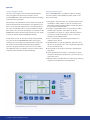
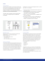
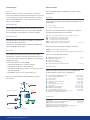
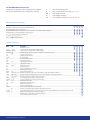
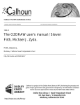
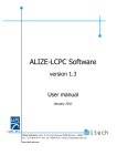
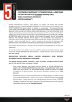
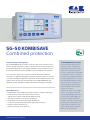
SG-50 KOMBISAVE
Combined protection
Precision actuation and triggering
SG-50 KOMBISAVE short profile
The SG-50 KOMBISAVE is a numeric protection and control device for use in
Combi protection with precision
medium voltage distribution systems, industry and uncoupling protection at
function in tailor-made designs
decentralised generators. The modular separation of the protection and con-
with variable transformer config-
trol functions means economic benefits in plant management are attained.
uration and selective protection
functions. Large colour display with
It is in protection technology in particular that we attach the greatest of
configuration options on site, func-
importance to quality and longevity. In addition to greater precision, the idea
tion and control data, maintenance
of simple and reliable configuration (familiar from the established telecontrol
and key-operated switch, 11-colour
systems of the series5) are also deployed in the SG-50 KOMBISAVE. Self-
LED with freely definable marking.
explanatory menu navigation means that manuals are broadly redundant.
14 binary inputs, 14 relays, 2 auxiliary voltages, RS-485 interface
with IEC 60870-5-103 protective
equipment coupling.
Typical fields of use
Optional: 26 inputs, U-input 400
• Definite/inverse time-delay overcurrent protection, simple or directional
V AC no VT, serial FO protective
• Power protection with optional automatic reclosing
coupling, IEC 60870-5-104 control
• Transformer protection with thermal dual body map
centre coupling, IEC 61850, logic
• Machinery protection, rotor blocking protection
function and plant automation.
• Earth fault protection with intermitting EF detection
Protection modules: Synchrocheck,
• Protection of decentralised generation plants (QU protection)
QU protection, fault location, poly-
• Busbar protection with H2 logic
gonal distance protection, surge
• Reserve protection in HV networks
guard, parallel power protection,
MHO circuit characteristics
SG-50 combination protection
Performance & quality
Integration into networks
Configuration
In addition to the high level of functionality whilst retain-
The large colour display with intuitive keypad and freely
ing simple operation, major significance is attached to the
programmable function buttons enable simple configura-
integration capability of the protection technology into
tion of the system. Comprehensive parameter records are
intelligent networks. As combination protective equipment,
generated on a PC using a configuration tool and loaded into
network control can be realised directly or via diverse
the system over a USB port. Parameter records and fault
telecontrol and substation automation capabilities.
records can also be transferred via a memory stick.
The optional DIGICOM-advanced PC software provides
The selective protective equipment coupling filters relevant
comprehensive analysis of the fault records.
process points for analysis in power system control. Fault
records can be automatically read by the series5 remote
Software
terminal unit from the protective equipment. The remote
The concept here is also aligned towards tailor-made
terminal unit logs the fault records in the Comtrade format
solutions and intuitive operation:
and makes them available for analysis in different ways.
• DIGICOM-basic:
The high level of flexibility of the SG-50 KOMBISAVE means
it can be deployed for an array of applications.
Base settings of protection parameters
• DIGICOM-advanced:
+ Online view of device status,
+ Measurement centre,
+ Service- and test functions,
+ Fault record analysis with DIGIVIEW
Infrastructure
Power
stations
Primary
Sub-
distribution
station
Green energy
Wind, photovoltaics
station
Local
network
stations
Industry in
general
Potential application areas
Power station protection
Thermal unit protection
Substation protection
Protection with integrated station automation
Measurement stations
Protected with directional earth protection
Industry
Protection for closely-meshed networks, poss. EF protection
Generation
Network uncoupling: QU protection
Secondary distribution
Autonomous protection, no battery supply
SG-50 combination protection
Office and business buildings
Purpose-built premises
Data centres
Residential
buildings
Green energy
Wind, photovoltaics
Operation
Simple, intelligible, flexible
Integrated operator panel
The much-praised approach of broadly self-explanatory
The SG-50 KOMBISAVE is operated on site from a clearly
menu navigation has also been provided for on the
structured, easily understandable operator panel on the
SG-50 KOMBISAVE, making manuals and expert knowledge
front of the device.
redundant during operation.
1 Fully graphic, high-resolution TFT display: Dynamic plant
All information and parameters can be read on the large dis-
visualisation makes it easier to gain an overview of the
play and be entered from the keyboard. Configuration from
plant status. Clearly legible text fields indicate at a glance
a PC is not an absolute requirement for simple applications.
For more complex applications and more efficient configur-
the important measured values.
2 11 freely programmable, three-coloured LEDs for status
ation, there is of course also the ability to connect the SG-50
and warning indications: These LEDs can be set
KOMBISAVE combi protective equipment to a PC over a USB
individually to red, green or orange, and be assigned to
port and to operate it with the DIGICOM software.
any functions (static and flashing). Push-in strips can
easily be used to label the LEDs.
A USB memory stick can be used to easily load parameter
records onto the SG-50 KOMBISAVE without using a PC.
Similarly, records of events and network faults can be read
via memory stick and later be analysed by the network
protection engineer from the comfort of his or her office.
The additional option of operation over the communication
interfaces offers a maximum level of flexibility.
3 Four conveniently positioned navigation buttons for
operation of the device.
4 Separate button for switching between "Remote control
(R)" and "Local operation (L)". Two orange LEDs signal the
current operating mode.
5 Two separate control buttons are used to activate plant
equipment.
6 Three separate function buttons: These buttons can be
assigned to frequently used functions, such as accessing
a particular menu.
7 Mechanical key-operated switch for interlocking switching
operations for example during maintenance.
SG-50 KOMBISAVE with standard plant visualisation
© SAE IT-systems GmbH & Co. KG
Control
Plant visualisation
The design of an installation and the equipment deployed
An example of control using the navigation buttons is shown
therein can be shown graphically. The acquisition of equip-
below with a circuit breaker:
ment states via SG-50 KOMBISAVE inputs enables the
dynamic visualisation of the current status of the real
installation. In addition, clearly legible text fields indicate at a
glance the most important measured values.
1 The "Control" menu is selected with the arrow buttons and
enabled with "Enter".
2 The arrow buttons are used to select the circuit breaker in
the visualisation system. Relevant supplementary
The graphic plant visualisation and the measured value
display can be configured easily from the DIGICOMPC software.
information is shown in the text field.
3 "Enter" is used to confirm the selection - available control
actions are displayed.
4 The required control action "Close" is selected with the
arrow buttons and confirmed with "Enter". The circuit
breaker is closed after a password is entered.
Plant visualisation and measured value view
Control of a circuit breaker
Equipment control
Logic functionality
Existing equipment can be controlled from the SG-50
The integrated, comprehensive and easily understandable
KOMBISAVE if it is connected to the outputs.
logic functionality enables new functions to be set up for
Control is either from:
automation of the switching station. This means diverse
• The integrated control panel
signals of the protective functions, the operator panel, the
• The binary inputs
binary inputs and outputs and control centre and virtual
• The control centre (network interfaces)
equipment signals (for outgoing line visualisation, equipment control) can be linked together. Various function
blocks are available for linking, including:
Switching sovereignty
• Logic gates
The switching sovereignty can be granted via binary inputs
• Counters
or the control centre. To guarantee safety, an R/L button can
• Timing relays
be used to disable the remote control capability (L) and to
• Memory
suppress every control command by a key-operated switch.
Local control is provided via the four navigation buttons on
Configuration of the logic is simple from the DIGICOM PC
the operator panel in conjunction with plant visualisation.
software. Understandability and simple operation are fea-
Two function buttons, "1" and "0", enable safe and efficient
tures of the autonomous concept for logic input and logic
operation of selected equipment.
processing in the SG-50 KOMBISAVE.
Comprehensive data interchange is provided with modern,
up-to-date standards.
SG-50 combination protection
Communication
Product selection
Protocols
The SG-50 KOMBISAVE is available tailor-made in many
Modern supervisory control centre systems use various
combinations:
protocols for data interchange. Direct integration of protocols
in the protective equipment enables seamless connection
Hardware
of the SG-50 KOMBISAVE to the substation automation of
It starts with the selection of the auxiliary voltage for supply
various manu–facturers.
and actuation:
IEC 60870-5-103
V1 16 to 160 V DC
V2 120 to 250 V DC/90 to 250 V AC
IEC 60870-5-103 is a standard for the transmission of protection data and fault records. The support of IEC 60870-5-
Then the necessary transformer configuration is determ-
103 via the EIA/RS-485 interface is included as default.
ined with the protective function required:
IEC 60870-5-104
IEC 60870-5-104 is a standard for integration into telecontrol and substation automation.
I2U0
I4U0
I4U1
I4U4
I4U4X
I8U0X
two current transformers CT (1 /5 A), no voltage converter VT
four CT (1 /5 A), no voltage converter VT
four CT (1 /5 A), one VT (100/110 V AC)
four CT (1 /5 A), four VT (100/110 V AC)
four CT (1 /5 A), four VT (100/110/400 V AC)
eight CT (1 /5 A), no voltage converter VT
from 1Q16
Transmission over Ethernet links (TCP/IP) is available with
Ethernet interface as an option.
Status and control signals I/O are always configured:
IEC 61850
BI14BO14 14 binary inputs, 14 outputs/relays
BI26BO14 26 binary inputs (2*DC/AC, 24*DC), 14 outputs/relays (2 high speed)
IEC 61850 is a general transmission protocol for station
Then there is the interface required:
automation for protection technology and supervisory control centres in electrical switching stations for mid and high
voltage technology.
Some of the definitions in IEC 61850:
RS RO EE EO WS EIA/RS-485 with IEC 60870-5-103:
EIA/RS-485 via fibre optics:
Ethernet over RJ-45: Ethernet over ST fibre optics: System interface (input for RTD-temp.-box) default
from 1Q16
• General specifications for switching stations
• Information for functions and equipment
Software options
• Information exchange for protection, monitoring, control
Please note that some functions are only available with
and measurement
• IEC 61850-8-1; block 1, 2, 5, 6, 9ab, 12ad, 13, 14
Electrical or optical Ethernet links (TCP/IP) are used for
transmission.
Control centre
IEC 60870-5-104
Coupling of protective equipment
Station bus
IEC 61850
certain hardware / transformer configurations.
04 Communication with IEC60870-5-104:
50 Communication with IEC61850:
SYSynchron-check:
QU QU protection:
UL Unterfrequency load shed UFLS
FO Fault location:
ZP Polygonal distance protection:
PE Surge guard:
PA Parallel power compensation:
MO MHO circuit characteristics:
LD Line differential protection from 1Q16
TF Differential protection for transformers from 1Q16
AU Customer-specific plant automation
requires EE/EO
requires EE/EO
requires I4U4
requires I4U4
requires I4U4
requires I4U4
requires I4U4
requires I4U4, ZP
requires I4U4, ZP
requires I4U4, ZP
requires I4U4
requires I8U0
IEC 60870-5-103 (RS-485)
Accessories
IEC 60870-5-103 (FO)
Possible structure of a communication network
© SAE IT-systems GmbH & Co. KG
User manual:
Deliverables in digital format
Customer-specific push-in strips. LED labelling:
Deliverables
DIGICOM-basic configuration software:
Deliverables
USB cable for connection to PC, 2m, type A-A
Assembly set, surface mounting with brackets and button bolts
DIGICOM-advanced (fault record analysis...)
SG-50 KOMBISAVE functional scope
Select here the options for the combination of protective
I2
=
two current transformers
functions and the transformer configuration required:
I4
=
four current transformers (e.g. IL1, IL2, IL3, IL0)
U0 =
no voltage converter
U1
one voltage converter
=
U4 =
four voltage converters (e.g. UL1, UL2, UL3, U0)
Measured values and displays
I2U0I4U0I4U1I4U4
LED (three-coloured, freely programmable, static, flashing)
11111111
Illuminated graphical TFT colour display
Network fault: Current (and voltage) per phase, KS duration, binary inputs/outputs, date/time
Event list with 1000 events, fault data recording max. 8 s
IL1, IL2, IL3, IL0, I15 min average, thermal Fill level
U0, UL1, UL2, UL3, UL12, UL23, UL31, f: ••••
••••
••••
••••
•
•
P, Q, S, cos , R/X, R0/X0, km/miles:
Protection functions
ANSIIEC
Description
Parameter records
50/51 overcurrent; two-stage, IOC and TOC selectable
I>, I>>
50N/51N IE>, IE>>
earth current; two-stage, IOC and TOC selectable
49 & 49II >
thermal overload; two body map for oil transformers, motors, lines, etc.
37 Undercurrent protection I<
48
Start-up time monitoring 66/86 Re-start inhibits 14 Rotor blocking protection 51M Load step protection 46 Out-of-balance protection
I2>
50BF Switch fail protection 79 Automatic reclosing
ARC
I2U0I4U0I4U1I4U4
2244
••••
•••
••••
••••
••••
••••
••••
••••
•••
••••
••••
••••
••••
••••
••••
••
••
•
•
•
•
•
•
•
•
•
•
•
•
•
68 Inrush protection
50 Short-circuit switch-on protection 85
Busbar protection to H2 74TC
TC
Trigger circuit monitoring
67N IE ger>, IE ger>> Dual directional earth connection; for insulated, compensated and fixed networks 67Ns IEE >, IEE >>
Dual directional intermitting earth connection; for isolated and compensated network 67 Iger>, Iger>>
Dual directional short-circuit protection; two-stage
27/59 V<, V>
Undervoltage/surge protection; both two-stage
81U/81O f<, f>
Under/over-frequency protection; both two-stage
47 V2>
Rotary field monitoring
QV
QU/QV protection (optional)
(
)
21FL
Fault locator (optional) (
)
25 Synchro-check (optional) (
)
81LSH Under frequency load shed UFLS (optional) (
)
Z< Current, UI, under-impedance excitation for distance protection (
)
21, 21N
Z
Polygonal multi-stage distance protection with 7 zones in forward/backward direction and managed zone Z1B (
)
21, 21N
Z
MHO circuit characteristics for distance protection (
)
Parallel power compensation for distance protection (
)
Surge guard for distance protection (
)
SG-50 combination protection
Technical data
Auxiliary source
Standards/tests
DC supply V1
Function range
Network failure bridging
16…160 V DC, <5 W
50 ms
AC/DC supply
Function range
Network failure bridging
V2
120 to 250 V DC/90 to 250 V AC, <5 VA
50 ms
Measurement inputs
Nominal frequency fN
50 or 60 Hz
Current inputs
Nominal current IN
Consumption per phase for IN
Accuracy for IN
2…40 x IN
40…100 x IN
Capacity continual
I1, I2, I3, I0
1 A and 5 A changeable via software
< 0.2 VA
< 0.5%
< 3%
< 10%
4 x IN
Thermal
100 x IN
Dynamic
250 x IN
Voltage inputs
Nominal voltage VN
Consumption per phase
Accuracy 0.25…2 x VN
Capacity 2 x VN continual
U1, U2, U3, U0/Ux
100 V / 110 V AC changeable via software
< 0.2 VA
< 0.5%
Binary inputs and outputs
Binary inputs BI14
14 inputs, 19 to 250 V AC/DC, < 2 mA
Binary inputs BI26
2 inputs, 19 to 250 V AC/DC, < 2 mA
24 inputs 24-60 V DC /70-250 V DC, < 2 mA
Binary outputs BO14
Permitted switched current
Limiting making capacity
Switch principle
14 relays, 250 V AC/DC, 2 high speed < 3 ms
8 A @ 240 V AC, resistive
8 A @ 30 V DC, resistive
0.4 A @ 110 V DC, resistive
2000 VA
normally open contact
Constructive features
Enclosure
Dimensions, installation
Dimensions, assembly
Weight
steel plate, 1.5 mm, zinc-plated, IP51
230×129×200 mm (W×H×T)
230×129×244 mm
approx. 3.5 kg
Terminals & connections
Current/voltage converterPlug-in terminals, fuseable, 35 A/250 VAC
Binary signalsPlug-in terminals, fuseable, 2.5 mm²
SupplyPlug-in terminals, fuseable, 2.5 mm²
USB
USB type A
EIA/RS-485 electrical Plug-in terminals, fuseable, 2.5 mm²
Ethernet electrical RJ45, TIA-568
Ethernet optical ST connector, 1300 nm, max. 1.5 km
© SAE IT-systems GmbH & Co. KG
Basic product standard
IEC 60255
Insulation test
Voltage test (routine test)
Voltage test (type approval)
IEC 60255-5
2.5 kV (EFF), 50 Hz, 1 min
5 kV (peak), 1.2/50 ms, 0.5 J
EMC testing (type approval)
IEC 60255-4 and -22, IEC 61000-4
High-frequency testing
Electrostatic discharge Radiation in HF field
Fast transient interference
Burst: ms
High-energy surge voltages
Surge: Conducted HF Magnetic field
IEC 60255-22-1: 2.5 kV (peak), 1 MHz
8 kV contact, 15 kV air discharge
10 V/m, 80 MHz to 2.7 GHz
4 kV, 5/50 ns, 5 kHz,
IEC 60255-22-4 and IEC 60255-4-4:
Burst length 15 ms, repetition rate 300
pulse 1.2/50 μs
IEC 61000-4-5
IEC 61000-4-6: 10 V, 150 kHz to 80 MHz
IEC 61000-4-8:
30 A/m continual, 300 A/m 3 s
Mechanical strength (type approval)
StandardsIEC 255-21-1, IEC 255-21-2, IEC 255-21-3,
DIN IEC 68-2-6
Earthquake resistanceNominal frequency: 1…35 Hz
Crossover frequency: 8…9 Hz
Horizontal: 3.5 mm; 10 m/s2
Vertical: 1.5 mm; 5 m/s2
Vibration loading
10…150 Hz; 0.075 mm; 1 g
Surge follow-up loadEa: 11 ms; 15 g, Eb: 16 ms; 10 g
Ambient conditions (type approval)
Standards
IEC 60255-6
Operating temperature
-10° C to +55° C
Storage temperature
-25° C to +55° C
Transport temperature
-25° C to +70° C
Relative humidityannual average: 75%, no condensation
95% at max. 40° C for 30 days
SG-50 KOMBISAVE product variants
Technical modifications and errors excepted. Product images may contain special features. Status: February 2015
Suggestions from the array of variations
Single IOC protector
• Single line protection with control
• Auxiliary voltage 48 V DC
• Communication IEC 60870-5-103/RS-485
SG-50-V1-I2U0-RS
Single IOC protector with EF
• Single line or motor protector with control (lines,
transformer, motors)
• Auxiliary voltage 240 V AC
• Communication IEC 60870-5-103/RS-485
SG-50-V2-I4U0-RS
Cost-effective distribution network protector
• IOC, directional EF,
• complex motor protection
• Auxiliary voltage 60 V DC
• Communication IEC 60870-5-103/RS-485
SG-50-V1-I4U1-RS
Directional IOC/EF protector
• Directional IOC, directional EF,
U<>, f<>, complex motor protection
• Auxiliary voltage 60 V DC
• Communication IEC 60870-5-103/RS-485
• optional with synchro-check, fault location extendible
SG-50-V1-I4U4-RS
QU/QV protection
• Reactive power undervoltage protection
© SAE IT-systems GmbH & Co. KG
All rights reserved
The guard5 series is developed and manufactured with precision in line with our principle
of supplying the highest quality and reliability.
The products are not commodity goods and
provision is made for customer requirements
provided they are permitted by the technology.
* Some of the patents and copyrights mentioned
in this brochure are held by NSE AG Switzerland
and are therefore subject to special protection.
• Communication IEC 60870-5-103/RS-485
• Distance protection optionally extendible
SG-50-V1-I4U4-RS-QU
Distance protection
• Directional IOC, directional EF, U<>, f<>
• Distance protection
• Auxiliary voltage 48 V DC
SAE IT-systems GmbH & Co. KG
• Communication IEC 61850 FO
Im Gewerbegebiet Pesch 14
• optional with MHO surge guard extendible
50767 Cologne, Germany
SG-50-V1-I4U4-RS-EO-50-ZP
Phone: +49 (0)221/59808-0
Fax: +49 (0)221/59808-60
[email protected]
www.sae-it.de
SG-50 combination protection