1
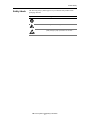
ChassisTouchTM 450 Monitor
User’s Installation Guide
Read and understand all safety information
before installing and using this product.
3M Touch Systems Proprietary Information
Copyright
This manual is © 3M 2003. All rights reserved.
Reproduction of the contents of this copyrighted manual in whole or in
part, by any means, electronic or mechanical, for any purpose, without
written permission of 3M Touch Systems, a subsidiary of 3M, is
prohibited.
Notice
Given the variety of factors that can affect the use and performance of a
3M Touch Systems Product (the “Product”), including that solid state
equipment has operation characteristics different from
electromechanical equipment, some of which factors are uniquely within
User’s knowledge and control, it is essential that User evaluate the 3M
Touch Systems Product and software to determine whether it is suitable
for User’s particular purpose and suitable for User’s method of
application. 3M Touch Systems’ statements, engineering/technical
information, and recommendations are provided for User’s convenience,
but their accuracy or completeness is not warranted. 3M Touch Systems
products and software are not specifically designed for use in medical
devices as defined by United States federal law. 3M Touch Systems
products and software should not be used in such applications without
3M Touch Systems’ express written consent. User should contact its
sales representative if User’s opportunity involves a medical device
application.
Important notice to
purchaser
Specifications are subject to change without notice. These 3M Touch
Systems’ Products and software are warranted to meet their published
specifications from the date of shipment and for the period stated in the
specification. 3M Touch Systems makes no additional warranties,
express or implied, including but not limited to any implied
warranties of merchantability or fitness for a particular purpose.
User is responsible for determining whether the 3M Touch Systems
Products and software are fit for User’s particular purpose and suitable
for its method of production, including intellectual property liability for
User's application. If the Product, software or software media is proven
not to have met 3M Touch Systems’ warranty, then 3M Touch Systems’
sole obligation and User’s and Purchaser’s exclusive remedy, will be, at
3M Touch Systems’ option, to repair or replace that Product quantity or
software media or to refund its purchase price. 3M Touch Systems has
no obligation under 3M Touch Systems’ warranty for any Product,
software or software media that has been modified or damaged through
misuse, accident, neglect, or subsequent manufacturing operations or
assemblies by anyone other than 3M Touch Systems. 3M Touch
Systems shall not be liable in any action against it in any way related
to the Products or software for any loss or damages, whether nonspecified direct, indirect, special, incidental or consequential
(including downtime, loss of profits or goodwill) regardless of the
legal theory asserted.
Edition
Document Number: 20375 (Rev. 2.0). April 2003.
Trademarks
MicroTouch, Near Field Imaging, and ChassisTouch are trademarks of
3M. Microsoft, Windows, and Windows NT are registered trademarks of
Microsoft Corporation
3M Touch Systems Proprietary Information
Important safety information
Intended use
The ChassisTouchTM 450 monitor is intended to provide touch screen functions
when connected to a host computer in an industrial setting. The ChassisTouch 450
monitor is not intended for use in hazardous locations.
The ChassisTouch 450 monitor is a component. After it is installed, the whole
system of which it is a part must be inspected to confirm seal ratings and
compliance with all local electrical codes.
Safety notices
Product safety information
DANGER
To reduce the risks associated with fire and explosion which, if not avoided, will cause death or
serious injury and/or property damage:
!
Do not install or use this product in a hazardous location.
WARNING
To reduce the risks associated with electrical shock, fire, or explosion which, if not avoided,
could result in death or serious injury and/or property damage:
!
!
!
!
!
!
!
!
!
!
!
!
Follow all product instructions.
Performance of all procedures described in this document should be by trained personnel.
Any servicing or other procedures not described in this manual are to be performed only by qualified
personnel.
Read and understand all safety information before installing and using the monitor.
Engineer the installation of the monitor to take into account the operating environment (e.g., shock/
vibration and/or thermal factors).
Properly install the monitor with a NEMA 4X gasket that is clean, undamaged, and effective.
Do not modify the monitor.
Use only 3M components or 3M-approved components for repairs.
If a replacement part is needed, contact 3M Touch Systems.
Provide a clean, reliable ground.
Use locking devices on connectors.
To ensure compliance with electrical codes and safe operation of the monitor, have a licensed
journeyman electrician familiar with local codes perform all wiring and installation tasks.
WARNING
To reduce the risks associated with electrical shock or fire which, if not avoided, could result in
death or serious injury and/or property damage:
!
!
If the monitor is mounted using a NEMA 4X panel gasket, install the unit in a Listed (UL) enclosure.
If the monitor will be used in corrosive environments, it is the responsibility of the user to test and
evaluate the unit in those environments. The monitor, as shipped, has not been evaluated for use in
excessively corrosive environments.
3M Touch Systems Proprietary Information
i
ChassisTouchTM 450 Monitor User’s Installation Guide
WARNING
To reduce the risks associated with electrical shock which, if not avoided, could result in death
or serious injury and/or property damage:
!
!
!
!
!
!
Make sure that the ground potential difference between the monitor and the host computer is less than
2V.
Before removing the monitor from its mounting or performing any other service to the monitor,
disconnect power to the unit.
Provide adequate strain relief for all communications and power cables.
Do not use a damaged power supply.
Do not use a power cable that is damaged or frayed or a power plug that is damaged.
Do not allow liquid inside the monitor’s metal enclosure
WARNING
To reduce the risks associated with electrical shock or mechanical function which, if not
avoided, could result in death or serious injury and/or property damage:
!
!
If your monitor will be used in an environment where safety is an issue, set the time for the WindowsTM
energy saver to be greater than the time for the Windows screen saver. Do not use a non-Windows
screen saver in an environment where safety is an issue.
If your monitor has a display power management system (DPMS) that is configurable from the display’s
on-screen Utility menu, do not turn off the DPMS.
WARNING
To reduce the risks associated with electric shock and/or burn-related injury that could result in
death or serious injury and/or property damage:
!
Do not open the power supply for the monitor. It contains hazardous voltage. The power supply has no
user-serviceable parts or adjustments inside.
WARNING
To reduce the risks associated with mechanical function which, if not avoided, could result in
property damage:
!
Do not operate the monitor in conditions outside of the operational specifications.
WARNING
To reduce the risks associated with skin contact or swallowing of cleaning solutions or fluids
which, if not avoided, may result in minor or moderate injury and/or cause property damage:
!
Refer to the cleaner manufacturer’s material safety data sheet (MSDS) and follow all instructions and
recommendations on product label.
CAUTION
To reduce the risks associated with muscle strain which, if not avoided, may result in minor or
moderate injury:
!
Avoid using the monitor for long periods of time without breaks.
CAUTION
To reduce the risks associated with eye strain which, if not avoided, may result in minor or
moderate injury:
!
Use the monitor where there is neither too much ambient light nor glare on the screen.
CAUTION
To reduce the risks associated with environmental contamination which, if not avoided, may
result in minor or moderate injury and/or cause property damage:
!
Dispose of the monitor according to applicable local, state, and federal government regulations.
3M Touch Systems Proprietary Information
ii
Product Safety
Safety labels
The following safety symbols appear on your ChassisTouch product and its
packaging materials:
Symbol
Meaning
Consult user instructions.
Warning: Hazardous voltage
Caution: Item is susceptible to electrostatic discharge
(ESD) damage if proper precautions are not taken.
3M Touch Systems Proprietary Information
iii
Contents
Chapter 1
Overview .................................................................. 1
Features.........................................................................................1
System requirements.....................................................................2
Packing list....................................................................................2
Related documents........................................................................2
Service and repair indicators ........................................................3
3M Touch Systems support services ............................................3
Chapter 2
Setting up the monitor ............................................ 5
Mounting and connecting .............................................................5
Installing NFI touch screen driver ..............................................10
Customizing NFI touch screen drivers .......................................11
Energy saver ...............................................................................11
Testing the monitor.....................................................................13
Chapter 3
Adjusting the video display.................................. 15
Controls for adjusting the video display.....................................15
OSD controls ..............................................................................16
Chapter 4
Maintenance and troubleshooting....................... 19
Maintaining your touch monitor.................................................19
Care and cleaning .......................................................................19
Troubleshooting..........................................................................20
Appendix
Specifications, standards, and certifications ..... 23
3M Touch Systems Proprietary Information
v
CHAPTER 1
Overview
About this chapter
This chapter presents an overview of the ChassisTouchTM 450 industrial monitor.
The topics covered in this chapter are:
!
Features of the ChassisTouch 450 monitor
!
System requirements of the host computer
!
Packing list for a standard ChassisTouch 450 monitor
!
Related documents
!
3M Touch Systems support services
Features
The ChassisTouch 450 monitor is a flat panel industrial monitor with the
following features:
!
MicroTouchTM Near Field ImagingTM (NFI) touch screen. The NFI touch
screen is durable (constructed of glass), reliable, and can be operated with
industrial gloves. It calculates touches electronically by measuring
disturbances in an electrostatic field near the surface of the screen.
The NFI touch screen comes with an anti-glare and anti-reflection coating.
!
Panel mountable with seal. The monitor comes ready to mount in a panel.
When properly mounted, the front of the monitor is sealed to NEMA 4X/
IP66 ratings.
!
Display. The monitor’s display is a 15-inch active matrix Thin Film
Transistor (TFT) Liquid Crystal Display (LCD). The ChassisTouch 450
monitor touch screen supports resolutions of 1024 x 768 (optimal),
800 x 600, and 640 x 480 pixels.
3M Touch Systems Proprietary Information
1
ChassisTouchTM 450 Monitor User’s Installation Guide
System requirements
The ChassisTouch 450 monitor requires a host computer that has:
!
An available RS-232 serial communication (COM) port.
!
A unique interrupt request (IRQ) available to the COM port that the
ChassisTouch 450 monitor will use. The monitor cannot share an IRQ with
another device.
!
A 9-pin to 25-pin adapter if the available serial port on the host computer has
25 pins.
!
A video card and video driver that is already installed. For instructions on
installing a video card and video driver, refer to your host computer’s
documentation or the video card manufacturer’s documentation.
Packing list
The ChassisTouch 450 monitor comes with the following items:
!
ChassisTouch 450 Monitor User’s Installation Guide (this manual)
!
AC power cable (North American)
!
AC/DC power supply (12 VDC output)
!
RS-232 serial cable
!
SVGA video cable
!
Full scale cutout template, locknuts, and washers for mounting the monitor in
a panel
!
Floppy disks with Near Field Imaging (NFI) touch screen drivers for
Windows XP Professional and Windows 2000 Professional operating
systems.
If your system requires Windows NT, Windows 98, or Windows 95 drivers,
they are available for download from www.3Mtouch.com.
!
Floppy disk with the linearization file for your NFI touch screen. If it is ever
necessary to uninstall and reinstall the touch screen driver software, you may
need the NFI linearization file from the floppy disk
Important
The linearization file for your monitor can also be retrieved from www.3Mtouch.com. You
will be prompted to enter your NFI touch screen serial number (located on the back of the
ChassisTouch 450 monitor).
Related documents
For information on how to install and customize driver software for the
ChassisTouch 450 monitor, refer to the software guide listed below that is
appropriate for your operating system. The software guides may be downloaded
from the 3M Touch Systems web site (www.3Mtouch.com).
!
For Windows XP Professional and Windows 2000 Professional operating
systems, refer to: MicroTouch NFI Software Guide: For Windows XP and
Windows 2000.
3M Touch Systems Proprietary Information
2
Overview
Note: To install drivers for Windows XP and Windows 2000 on the
ChassisTouchTM 450 monitor, follow installation instructions on page 10 of
the ChassisTouch 450 User’s Installation Guide.
!
For Windows NTTM 4.0, Windows 98, and Windows 95 operating
systems, refer to NFI Touch Screen Software User’s Guide: For Windows
NT, Windows 9X, Windows 3.1, and MS-DOSTM.
Note: The sections of this software guide that pertain to Windows 3.1 and
MS-DOS are not applicable to the ChassisTouch 450 monitor.
Service and repair indicators
Do not attempt to service this unit yourself. Removing the display cover may
expose you to dangerous voltage or other risks. Disconnect power from the
display and contact 3M Touch Systems technical support staff in the event that the
monitor:
!
Does not operate properly when the operating instructions are followed.
!
Has been dropped or the metal enclosure has been damaged.
!
Exhibits a distinct change in performance, indicating a need for service.
!
Has a power cable that is damaged of frayed or a power plug that is damaged.
!
Has liquid inside its metal enclosure.
3M Touch Systems support services
3M Touch Systems provides extensive support services through our website and
technical support organization.Visit the 3M Touch Systems website at
www.3Mtouch.com where you can download touch screen software and drivers,
obtain regularly updated technical documentation on 3M Touch Systems
products, and learn more about our company.
Whenever you contact Technical Support, please provide the following
information:
!
Part number and serial number from your monitor and the serial number of
the NFI touch screen (both numbers are on the exterior of the monitor’s metal
enclosure)
!
Current driver version
!
Operating system used
!
Information on additional peripherals
Technical support is available Monday through Friday 8 a.m. to 8 p.m. US Eastern
Standard Time (9 a.m. to 5 p.m. throughout Europe). Limited call back service is
available on Saturdays and Sundays.
You can contact 3M Touch Systems Technical Support (US only -- Eastern
Standard Time) by calling the hot line or sending a fax.
!
Technical Support Hot Line: 978-659-9200
!
Technical Support Fax: 978-659-9400
!
Toll Free: 1-866-407-6666
!
Email: [email protected]
3M Touch Systems Proprietary Information
3
ChassisTouchTM 450 Monitor User’s Installation Guide
3M Touch Systems Worldwide Offices
All offices can be reached through the web site: www.3Mtouch.com.
Country
Telephone
United Kingdom
+ 44 (0) 1235-444400
United States
978-659-9000
Australia
+61 395-82-4799
Canada
604-521-3962
France
+33 (1) 45-13-90-30
Germany
+49 (0) 2131-14-0
Hong Kong/China
(852) 2333-6138
Italy
+39 (0) 39-230-2230
Japan
+81 (4) 4811-1133
Korea
+822 552 3198
Singapore
+65-96279173
Spain
+34 934-15-6285
Taiwan
+886-2-2704-9011
3M Touch Systems Proprietary Information
4
CHAPTER 2
Setting up the monitor
About this chapter
This chapter describes how to:
!
!
!
!
!
!
Mount the ChassisTouchTM 450 monitor in a panel to achieve a NEMA 4X/
IP66 seal around the front of the unit.
Connect communications cables.
Connect power.
Install Near Field ImagingTM (NFI) touch screen driver software.
Make recommended energy saver settings if the ChassisTouch 450 monitor
will be used in a setting where safety is an issue.
Test the monitor.
Mounting and connecting
Materials supplied
!
!
!
!
14 nylon insert hex locknuts (size M5 x 0.80)
14 steel washers (15 mm outside diameter)
1 full-scale panel cutout template
1 panel gasket (already installed)
Note: If it is ever necessary to remove the ChassisTouch from its panel
mount and remount, be sure to install a new front panel gasket (for ordering
information, see “3M Touch Systems support services” on page 3). Re-using
a panel gasket could compromise the NEMA 4X seal.
DANGER
To reduce the risks associated with fire and explosion which, if not avoided, will cause death or
serious injury and/or property damage:
!
Do not install or use this product in a hazardous location.
3M Touch Systems Proprietary Information
5
ChassisTouchTM 450 Monitor User’s Installation Guide
Steps for mounting and connecting
WARNING
To reduce the risks associated with electrical shock, fire, or explosion which, if not avoided,
could result in death or serious injury and/or property damage:
!
!
!
Follow all product installation instructions.
Performance of all procedures described in this document should be by trained personnel.
Engineer the installation of the monitor to take into account the operating environment (e.g., shock/
vibration and/or thermal factors).
WARNING
To reduce the risks associated with electric shock and/or burn-related injury that could result in
death or serious injury and/or property damage:
!
Do not open the power supply for the monitor. It contains hazardous voltage. The power supply has no
user-serviceable parts or adjustments inside.
WARNING
To reduce the risks associated with electrical shock or fire which, if not avoided, could result in
death or serious injury and/or property damage:
!
If the monitor will be used in corrosive environments, it is the responsibility of the user to test and
evaluate the unit in those environments. The monitor, as shipped, has not been evaluated for use in
excessively corrosive environments.
To panel mount the monitor and achieve a NEMA 4X/IP66 seal, follow these
steps:
Important
The ChassisTouch 450 monitor is designed to be mounted in a panel. If you choose to
VESA-mount the monitor, use 6 mm screws with a mounting plate that is 1.6 mm thick. If
the mounting plate is a different thickness, adjust the screw length accordingly.
1.
Tape the full-scale cutout template onto the panel where you want to mount
the monitor.
2.
Using the template as your guide, cut out the panel.
3.
Drill holes through the cutout and into the panel, deburr all cuts and holes,
and follow the instructions that appear on the cutout template.
4.
Bring the power cable and the communications cable up to the cutout.
WARNING
To reduce the risks associated with electrical shock, fire, or explosion which, if not avoided,
could result in death or serious injury and/or property damage:
!
!
!
Engineer the installation of the monitor to take into account the operating environment (e.g., shock/
vibration and/or thermal factors).
Provide a clean, reliable ground.
To ensure compliance with electrical codes and safe operation of the monitor, have a licensed
journeyman electrician familiar with local codes perform all wiring and installation tasks.
Depending on connector depth and cabinet space, you may have to make
your connections at this point, before installing the unit in the cutout. If so,
skip to steps 9 and 10 and then come back come back to step 5.
5.
Place the monitor in the cutout, aligning the studs with the holes in the panel.
You may need assistance at this point to hold the unit in place.
3M Touch Systems Proprietary Information
6
Setting up the monitor
WARNING
To reduce the risks associated with electrical shock or fire which, if not avoided, could result in
death or serious injury and/or property damage:
!
If the monitor is mounted using a NEMA 4X panel gasket, install the unit in a Listed (UL) enclosure.
6.
Insert the unit in the cutout until the gasket material makes full contact with
the panel.
WARNING
To reduce the risks associated with electrical shock, fire, or explosion which, if not avoided,
could result in death or serious injury and/or property damage:
!
!
Properly install the monitor with a NEMA 4X gasket that is clean, undamaged, and effective.
Use only 3M components or 3M-approved components for repairs.
7.
Attach the monitor to the panel from the back using the locknuts and
washers supplied.
8.
Gradually tighten diagonal pairs of locknuts until the height of the panel
gasket is compressed to between 0.125 inches (3.175 mm) and 0.1 inches
(2.54 mm).
Important
Do not overtighten the panel mounting locknuts. If the gasket is compressed to a height that
is less than 0.1 inches (2.54 mm), the NEMA 4X/IP66 seal may be compromised and the
3M Touch Systems warranty will be invalidated.
ChassisTouch 450 Monitor
Panel
Locknut
ChassisTouch 450
Monitor
Washer
Gasket
Figure 1: Panel mounting the monitor
9.
Before making cable connections, make sure that an appropriate video card
and video driver is installed on the host computer. For information on
installing the video card and video driver, refer to your video card
manufacturer’s documentation.
The ideal video settings for the ChassisTouchTM 450 monitor are:
!
Display mode (also called “desktop area” or “video resolution”):
1024 x 768
3M Touch Systems Proprietary Information
7
ChassisTouchTM 450 Monitor User’s Installation Guide
!
Refresh rate (also called “vertical scan rate” or “vertical sync”): 60 Hz
!
Color depth (also called “color palette” or “number of colors”): 3M Touch
Systems recommends that color depth be set at no less than 16-bit (high
color).
The video card must support one of the display modes specified in Table A.
If you select an unsupported video mode, the monitor will stop working or
display an unsatisfactory picture quality.
Table A: Supported display modes and refresh rates
Display Mode
Refresh Rate (Hz)
VGA (640 x 480)
60
75
85 (15” failsafe mode)
SVGA (800 x 600)
56
60
75
85 (15” failsafe mode)
XGA (1024 x 768)
60
75
85 (15” failsafe mode)
Many video cards initially display a screen image at the VGA or SVGA
resolution. The ChassisTouch 450 monitor supports these resolutions (Table
A), and so can display the desktop controls that let you change to the optimal
resolution of 1024 x 768. For information on how to change resolution, see
“Controls for adjusting the video display” on page 16.
10. Connect communications and power cables to the ChassisTouch 450
monitor by following these steps:
WARNING
To reduce the risks associated with electrical shock, fire, or explosion which, if not avoided,
could result in death or serious injury and/or property damage:
!
!
Use locking devices on connectors.
To ensure compliance with electrical codes and safe operation of the monitor, have a licensed
journeyman electrician familiar with local codes perform all wiring and installation tasks.
a) Make sure that the host computer is powered off.
3M Touch Systems Proprietary Information
8
Setting up the monitor
b) Connect one end of the video cable to the video connector on the
ChassisTouchTM 450 monitor and then connect the other end to the video
card in the host computer (Figure 2).
Typical host computer
ChassisTouch 450 monitor
OSD buttons
and LED
RS-232 serial
touch screen cable
Power supply
cable
Video cable
AC/DC power supply
Figure 2: Connecting communications and power cables
c) Connect one end of the RS-232 serial touch screen cable to the
ChassisTouch 450 monitor and then connect the other end to an available
serial communication (COM) port on the back of the host computer.
Important
Be sure to tighten all cable connections.
!
!
Route all wiring and cabling away from heat sources and sharp metal edges to avoid
damage.
3M Touch Systems Proprietary Information
9
ChassisTouchTM 450 Monitor User’s Installation Guide
Important
The ChassisTouch 450 monitor must be operated with the original power supply.
d) Plug the AC/DC power supply into the ChassisTouch 450 monitor. Be
sure to use the power supply included with the monitor.
WARNING
To reduce the risks associated with electrical shock which, if not avoided, could result in death
or serious injury and/or property damage:
!
Make sure that the ground potential difference between the monitor and the host computer is less than
2V.
e) Connect the power cable to the power source. After connecting power,
the monitor will automatically power on and the LED on the back of the
monitor will be illuminated (for location of LED, see Figure 2 on
page 9). If the LED is not illuminated try pressing the Power button
located on the back of the monitor. If the LED still is not illuminated,
check that the power supply is functioning properly.
Installing NFI touch screen driver
The Near Field ImagingTM (NFI) touch screen driver enables the monitor to work
with the host computer.
NFI drivers for Windows XP Professional and Windows 2000 Professional
operating systems came on floppy disks with your ChassisTouch 450 monitor.
The ChassisTouch 450 monitor ships with the linearization data pre-installed, so
when you are prompted to install the linearization file, select Skip. If you ever
need to reinstall the linearization file, you can find it in one of two places:
!
!
A floppy disk that came with your monitor
On www.3Mtouch.com. To download the linearization file from the web
site, you will be prompted to enter your NFI touch screen serial number
(located on the back of the ChassisTouch 450 monitor).
Installing the driver for Windows XP/2000 operating
systems
To install touch screen software for Windows XP or Windows 2000 operating
systems:
1.
Close all open programs.
2.
Find the floppy disk that includes the driver for Windows XP/2000 operating
systems, insert it in the disk drive, and browse the floppy disk to find the file
named setup.exe.
3.
Open setup.exe. The installation Welcome window appears.
4.
Follow the screen prompts to install the driver and then follow the on-screen
instructions of the Setup Wizard.
3M Touch Systems Proprietary Information
10
Setting up the monitor
5.
Follow the Setup Wizard’s on-screen instructions. The Wizard sets the
baseline for the touch screen controller, downloads linearization data to the
controller, and aligns the touch screen to the physical display.
Important
The ChassisTouchTM 450 monitor ships with the linearization data pre-installed, so when
you are prompted to install the linearization file, select Skip
6.
When the Wizard finishes setting up the software, an Install Successful
window appears.
7.
For more information on how to customize NFI drivers for Windows XP and
Windows 2000 operating systems, see the NFI Touch Screen Software
System Software User’s Guide (for Windows XP and 2000). The guide is
available for download at www.3Mtouch.com.
Installing the drivers for Windows NT 4.0 and Windows
9X operating systems
NFI drivers for Windows NT, Windows 98, and Windows 95 are available for
download at www.3Mtouch.com. For instructions on installing and customizing
these drivers, see the NFI Touch Screen Software System User’s Guide (for
Windows NT, 9X, 3.1., and DOS). The guide is available for download from
www.3Mtouch.com.
Customizing NFI touch screen drivers
The NFI touch screen driver settings that can be modified include:
!
Sensitivity of the screen to touches.
!
Access to right mouse button functions by touch.
!
Response time of the touch screen to double touches.
For instructions on how to customize touch screen settings, refer to the
NFI software user’s guide that is appropriate for your operating system. Software
guides are listed in “Related documents” on page 2.
Energy saver
The ChassisTouch 450 monitor conforms to the Video Electronics Standards
Association (VESA) Display Power Management Signaling (DPMS) standard. To
benefit from power management (or “energy saver”), the monitor must be used in
conjunction with a computer and video card that implements the VESA DPMS
standard.
3M Touch Systems Proprietary Information
11
ChassisTouchTM 450 Monitor User’s Installation Guide
Safety recommendations
If the ChassisTouch 450 monitor is used in a setting in which unintentionally
activating a button on the touch screen might have harmful consequences for
people or equipment, 3M Touch Systems makes the following recommendations:
!
Set “System Standby” to “Never” in the power dialog box of your Windows
!
Do not use the Power button located on the back of the ChassisTouch 450
operating system.
monitor. The Power button can be used to manually turn the backlights on and
off.
!
Make the following changes in the Display Properties dialog box of your
Windows operating system:
1. On the host computer, close all Windows applications and then open the
Display Properties dialog box.
2. In the Screen Saver tab of the dialog box, choose the number of minutes
that you want to elapse from the last time the screen is touched to when
the screen saver will activate.
3. Select the power button (also located in the Screen Saver tab). A power
dialog box appears.
Important
The power button is labelled differently in different operating systems:
In Windows XP and Windows 2000: Power
!
!
In Windows 9X (in the section of the dialog box named “Energy Saving Features of the
monitor”): Settings
4. In the Turn off monitor pull-down menu, choose the number of minutes
that will elapse from the last time the screen is touched to when the
energy saver will be activated. The period chosen must be greater than
the period you chose for the screen saver.
5. Select OK.
WARNING
To reduce the risks associated with electrical shock or mechanical function which, if not
avoided, could result in death or serious injury and/or property damage:
!
!
If your monitor will be used in an environment where safety is an issue, set the time for the Windows
energy saver to be greater than the time for the Windows screen saver. Do not use a non-Windows
screen saver in an environment where safety is an issue.
If your monitor has a display power management system (DPMS) that is configurable from the display’s
on-screen Utility menu, do not turn off the DPMS.
3M Touch Systems Proprietary Information
12
Setting up the monitor
Testing the monitor
To test that the monitor is working properly:
1.
Turn on the host computer.
WARNING
To reduce the risks associated with mechanical function which, if not avoided, could result in
property damage:
!
Do not operate the monitor in conditions outside of the operational specifications.
2.
Make sure the video image is displayed on the monitor’s display. If it is not
visible, first check to see if the LED on the back of the monitor is flashing
orange-to-green. If not, press the Power button on the back of the monitor
(see Figure 3 on page 16).
3.
If the LED is flashing, the host computer’s operating system has an energy
saver setting that has timed out.
If you do not want the energy saver to be active and the monitor is not in a
location where safety is a concern (see “Safety recommendations” on
page 12), turn off the operating system’s energy saver. With this setting, any
touch to the touch to the touch screen will activate the display and will be
recognized by the controller as a touch.
4.
Make sure the video display is centered on the screen. If it needs centering,
follow instructions for auto adjusting the display on page 16.
If the image is still not satisfactory after auto adjusting, follow instructions
on page 17 for manually adjusting horizontal and vertical display settings.
3M Touch Systems Proprietary Information
13
CHAPTER 3
Adjusting the video display
Your ChassisTouchTM 450 monitor has several control buttons and an on-screen
menu for adjusting the video display. For example, you can adjust:
!
Pixel clock and phase to eliminate noise.
!
Image contrast and brightness to your lighting conditions.
!
Horizontal and vertical position of the image.
This chapter explains presents guidelines for adjusting the video display and
describes how to use the available monitor controls to adjust the image to your
liking.
Before you make any adjustments:
!
Set the controls in normal lighting conditions.
!
Display a test image or pattern while making video adjustments.
!
It is recommended that you first set display settings with the video driver on
your host computer. After establishing video driver settings, run AUTO using
the monitor’s OSD controls. AUTO and other OSD functions are explained in
“OSD controls” in Table B.
Controls for adjusting the video display
Your ChassisTouch 450 monitor has five controls for adjusting the video display
(Table B). On the back panel there is also an LED indicator and a Power button.
Pressing the Power button turns the monitor’s backlights on or off but does not
affect power to the monitor.
3M Touch Systems Proprietary Information
15
ChassisTouchTM 450 Monitor User’s Installation Guide
Table B: OSD functions and locations of video controls on back panel of the monitor
Name
MENU
Function of the control
!
!
!
EXIT
!
!
UP
!
DOWN
!
AUTO
!
Video controls on back of ChassisTouch 450 monitor
The first press of the menu button calls
up the On Screen Display (OSD).
A second press enters the current submenu of the OSD.
LED
Additional presses allow you to cycle
through the available sub-menu options.
Power
Returns to the previous OSD menu
level.
If you are at the top level, this closes the
OSD display.
Increases the value of the selected
menu option.
MENU EXIT
UP
DOWN
AUTO
Decreases the value of the selected
menu option.
Brings video settings to their optimal
level.
OSD controls
Selecting MENU will pull up the On Screen Display (OSD) menu, as shown in
Figure 3.
Figure 3: ChassisTouch 450 monitor On Screen Display (OSD) menu
Auto adjustment
Selecting AUTO on the OSD menu will start an auto adjustment of the monitor’s
video settings to their optimum level. If necessary, you can fine tune the
parameters by selecting the PC icon and adjusting the options as explained below:
3M Touch Systems Proprietary Information
16
Adjusting the video display
Brightness
Selecting the Brightness option (as in Figure 3) allows you to adjust the brightness
of the display. Adjust the brightness using the UP and DOWN buttons. Press EXIT
to confirm a setting.
Contrast
Selecting Contrast allows you to adjust the overall contrast of the display. To
change the setting, use the UP and DOWN buttons. Press EXIT to confirm a setting.
Phase
If the phase of your monitor is not fine-tuned, you may observe unstable
horizontal noise lines and cross-talking, stretching from the edge of small
windows on your display.
To reduce this horizontal noise, follow these steps:
1. From the Windows desktop of the host computer, select Start and then select
Shut Down. The Windows Shut Down dialog box appears on the monitor’s
display. (Visual noise is more visible and easier to eliminate if the display is
in Windows Shut Down mode.)
2. Press the Menu control button to call up the OSD main menu, select the PC
icon, and then select the Phase sub-menu.
3. Press the UP or DOWN control buttons to reduce the noise. To confirm a new
phase setting, press the EXIT control button.
4. After adjusting the phase setting, select Cancel in the Windows Shut Down
dialog box to return to your original Windows display.
Frequency
If the Frequency setting is not fine-tuned, you may observe periodic vertical bars
of video noise.
To reduce this vertical noise, follow these steps:
1. Select AUTO in the OSD menu to auto adjust the monitor’s display (see
“Auto adjustment” on page 16).Vertical noise is usually adjusted out
when the display is auto adjusted.
If there is still noise after auto adjusting the display, adjust the OSD
Frequency setting.
2. Press the Menu control button to call up the OSD main menu, select the
PC icon, and then select the Frequency sub-menu.
3. Press the UP or DOWN control buttons so that the vertical bars of noise
disappear completely or so that an even amount of noise is distributed
across the entire screen. To confirm a new frequency setting, press the
EXIT control button.
4. If there is any remaining noise on the screen, adjust the Phase setting (see
“Phase” on page 17).
H-Position, V-Position
Selecting the H-Position or V-Position sub-menu allows you to adjust the
horizontal/vertical position of the displayed image. Press the UP or DOWN control
buttons to adjust the position of the video image. To confirm a new position
setting, press the EXIT control button.
3M Touch Systems Proprietary Information
17
ChassisTouchTM 450 Monitor User’s Installation Guide
Sharpness
Selecting the Sharpness sub-menu allows you to adjust the sharpness of the video
image, especially when low resolutions are displayed). Press the UP or DOWN
control buttons until the desired sharpness is achieved. To confirm a new
sharpness setting, press the EXIT control button.
Color Temperature
Selecting the Color Temperature sub-menu allows you to adjust the color balance
and level of the display. There are three pre-set color settings (Red, Green, Blue)
and an option for resetting factory default values for color (User Color Reset).
By adjusting a single color, you can make the picture look warmer (biased towards
red) or cooler (biased towards blue). Adjusting all three levels will make colors
appear more or less striking.
OSD (on-screen display) menu
Selecting the OSD icon allows you to alter how the OSD menu appears. The
following adjustments can be made:
!
H-Position and V-Position allow you to adjust the horizontal/vertical
position of the OSD menu on the display.
!
OSD Timeout allows you set how long the OSD menu will appear on the
display between touches to the screen.
!
Language allows you to choose the language used in the OSD menu and
sub-menus (default is English).
Utility menu
The Utility sub-menus that are accessible by the user are:
!
Reset allows you to reset OSD settings to factory defaults by selecting Yes.
!
Half Tone allows you to make OSD menus transparent by selecting Yes.
Neither Dynamic Brightness nor Information is configurable by the user.
3M Touch Systems Proprietary Information
18
CHAPTER 4
Maintenance and troubleshooting
If you have a problem setting up or using your monitor, you may be able to solve
it yourself. Before calling 3M Touch Systems, try the suggested actions that are
appropriate for the problems you are experiencing with the monitor. You may also
want to consult your video card user’s manual for additional troubleshooting
advice.
Maintaining your touch monitor
To maintain your display and keep your monitor operating at peak performance:
!
Keep your monitor and screen clean.
!
Adjust the monitor video controls. Refer to Chapter 3 for more information.
!
Do not install the display in a place where ventilation may be hindered.
Always maintain adequate ventilation to protect the display from
overheating and to ensure reliable and continued operation.
Care and cleaning
Touch screen
The touch screen requires very little maintenance. 3M Touch Systems
recommends that you periodically clean the glass touch screen surface. 3M Screen
Cleaner 675 has been tested and approved for this use.
When cleaning your touch screen:
WARNING
To reduce the risks associated with skin contact or swallowing of cleaning solutions or fluids
which, if not avoided, may result in minor or moderate injury and/or cause property damage:
!
Refer to the cleaner manufacturer’s material safety data sheet (MSDS) and follow all instructions and
recommendations on product label.
!
Do not use any chemical that corrodes glass or any vinegar-based solutions.
!
Apply the cleaner with a soft, lint-free cloth. Avoid using gritty cloths.
!
Always dampen the cloth and then clean the screen. Be sure to spray the
cleaning liquid onto the cloth, not the screen.
!
Always handle the touch screen with care. Do not pull or stress cables.
3M Touch Systems Proprietary Information
19
ChassisTouchTM 450 Monitor User’s Installation Guide
Bezel
An isopropyl (or ethanol) alcohol and water solution ratio of 50:50 is the best
cleaning agent for your bezel. Apply the alcohol solution to a cotton gauze or soft
cotton cloth and then clean the bezel with the cloth. Do not apply the cleaning
agent directly to the bezel.
WARNING
To reduce the risks associated with skin contact or swallowing of cleaning solutions or fluids
which, if not avoided, may result in minor or moderate injury and/or cause property damage:
!
Refer to the cleaner manufacturer’s material safety data sheet (MSDS) and follow all instructions and
recommendations on product label.
Troubleshooting
If you have a problem setting up or using the ChassisTouch 450 monitor or the
monitor’s NFI touch screen, you may be able to solve it yourself. Before calling
3M Touch Systems, try the strategies discussed in this chapter that address the
problems you are experiencing. If the problem seems to be video-related, you
should also consult the documentation that came with the video card in your host
computer.
WARNING
To reduce the risks associated with electrical shock, fire, or explosion which, if not avoided,
could result in death or serious injury and/or property damage:
!
!
!
Do not modify the monitor.
Do not substitute components.
Use only 3M components or 3M-approved components for repairs.
WARNING
To reduce the risks associated with electrical shock which, if not avoided, could result in death
or serious injury and/or property damage:
!
Before removing the monitor from its mounting or performing any other service to the monitor,
disconnect power to the unit.
Monitor installation
No image
displayed (blank
screen)
Is the monitor receiving power? Make sure that:
Host computer’s power cable is connected properly and securely
to its power source.
Monitor’s power cable is connected properly and securely to the
power source.
AC/DC power supply is connected to the monitor properly and
securely and the LED on the AC/DC power supply is lit green.
LED on the rear of the display is lit green. If it is not, try pressing
the Power button on the rear of the monitor.
Try using another power cable.
!
!
!
!
!
3M Touch Systems Proprietary Information
20
Maintenance and troubleshooting
Is the monitor receiving a valid video signal from the host
computer? Make sure that:
Host computer is powered on.
Video cable is connected properly and securely to monitor and
computer.
LED on the rear of the display is lit green. If it is not, try pressing
the Power button on the rear of the monitor.
No pins are bent in the video cable connector.
Video card is seated firmly in the card slot in the host computer.
Host computer is using a supported display mode and video input
from the video card that are within the range of refresh rates for
the display (see "Table A" on page 8).
!
!
!
!
!
!
Is the monitor in energy saver mode?
If the LED on the rear of the monitor is flashing orange-to-green,
to restore operation try one or more of the following:
Touch the screen.
Note: If the touch screen is in a setting where safety is an issue
and the recommended settings to the Display Properties dialog
box have been made (see “Safety recommendations” on
page 12), a first touch to reactivate the backlights will not
activate the touch screen until it is touched a second time (see
“Testing the monitor” on page 13).
Press any key on the keyboard.
Move the mouse.
!
!
!
!
Are the brightness and contrast settings too low?
1. Use the host computer’s video driver to set brightness, contrast,
and other video settings.
2. Use the monitor’s on-screen display controls to Auto adjust the
display settings.
3. If the brightness and contrast (or other display settings) are still not
satisfactory, use OSD menus and sub-menus to modify display
features (see “OSD controls” on page 16).
Abnormal image
Make sure that:
Video input from the video card falls within the refresh rate of the
display (see "Table A" on page 8).
Video cable is connected properly and securely to the monitor and
the host computer.
!
!
Colors of image
are abnormal
Make sure that:
Video cable is connected properly and securely to the monitor and
the computer.
No pins are bent in the video cable connector.
Set colors using your video driver and then auto adjust the
monitor’s OSD settings (for details, see “Controls for adjusting the
video display”, page 15).
!
!
!
Disturbances on
the screen
!
Make sure that the video display settings are correct (see “Controls
for adjusting the video display” on page 15 ).
3M Touch Systems Proprietary Information
21
ChassisTouchTM 450 Monitor User’s Installation Guide
NFI touch screen
If you are experiencing problems with the touch screen, check the following list
of possible issues. For a list of NFI touch screen error messages and their
meanings, refer to the NFI software user’s guide that is appropriate for your host
computer’s operating system (see “Related documents” on page 2).
Touch screen
does not
respond to touch
!
!
!
!
Cursor is not
located directly
underneath your
finger
!
Cursor is
extremely jittery
or erratic
!
Make sure that all cables are properly connected properly. Review
set up procedures (Chapter 2).
Power down the monitor, wait a few seconds, and then power up the
monitor again.
After installing the touch screen driver software, restart the host
computer to activate the driver.
Check the communication settings. Is the touch screen trying to use
the same COM port or IRQ as another device (for example, a
mouse)? If so, a hardware device conflict will result and the touch
screen will not work.
Align the touch screen by following instructions that appear in the
NFI software user’s guide that is appropriate for the host computer’s
operating system (for available software user’s guides, see
“Related documents” on page 2).
Adjust the refresh rate using the host computer’s video driver and
then use the monitor’s OSD control buttons to auto adjust the
monitor’s display settings. For more information on video settings,
see “Controls for adjusting the video display” starting on page 15.
3M Touch Systems Proprietary Information
22
APPENDIX
Specifications, standards, and
certifications
Enclosure and cutout dimensions
2.14"
(54.22 mm)
16.14"
(410.00 mm)
12.76"
(324.00 mm)
12.76"
(324.00 mm)
Figure 4: Front and side views of the ChassisTouchTM 450 monitor with
dimensions
Table C: Enclosure and cutout dimensions
Imperial
Metric
Enclosure
12.76" high × 16.14" wide ×
2.14" deep
324.00 mm high × 410.00 mm
wide × 54.22 mm deep
Panel cutout
11.05" high × 14.50" wide
280.72 mm high ×
368.27 mm wide
Mounting
clearances
2" all around
51 mm all around
Weight
14 lbs
6.35 kg
Panel stud length
0.63”
16 mm
Thread
--
M5
3M Touch Systems Proprietary Information
23
ChassisTouchTM 450 Monitor User’s Installation Guide
Panel cutout dimensions
17.00"
(431.80 mm)
14.41"
(366.01 mm)
14.03"
(356.37 mm)
10.47"
(265.94 mm)
8.5"
(215.90 mm)
CL
6.53"
(165.90 mm)
2.97"
(75.44 mm)
Cutout line
2.59"
(65.79 mm)
Radius .10"
(2.54 mm)
typical
.00"
Diameter .24" (6.10 mm)
typical
CL
Display specifications
Operating values given are at room temperature (25°C +/- 5°C).
Display size and viewing area (diagonal)
15"
Maximum resolution
1024 X 768 XGA
Type
Color Active TFT
Panel colors (up to)
16.7 M
Contrast ratio (typical)
300:1
Brightness without touch screen (typical)
250 cd/m2
Brightness with touch screen (typical)
230 cd/m2
Viewing angle (typical)
H ± 65°
V +50° to -60°
Backlight life expectancy (typical)
35,000 hr
3M Touch Systems Proprietary Information
24
Specifications, standards, and certifications
Chemical resistance
Bezel
The bezel provides resistance to user abuse and to most chemicals and other
substances.
Touch screen
The MicroTouchTM Near Field ImagingTM (NFI) touch screen is made of glass and
will withstand most chemicals and their concentrations that do not corrode glass.
Supported operating systems
NFI touch screen drivers for Windows XP Professional and Windows 2000
Professional operating systems ship (on floppy disk) with the ChassisTouch 250
monitor.
NFI drivers for the following operating systems may be downloaded at
www.3Mtouch.com:
!
Windows NT
!
Windows 98
!
Windows 95
Communications
The communications ports available on the ChassisTouch 450 monitor are:
!
RS-232C compatible asynchronous serial port
!
15-pin female video connector
Power
With the AC/DC power supply, the output power is 12 VDC.
Operating conditions
Condition
Range
Operating temperature
0°C to 50°C (32°F to 122°F)
Humidity
50°C, 5% to 95% non-condensing
Maximum operating altitude
6,560 feet (2,000 meters)
Vibration
5 to 57 Hz 0.006 in peak displacement
58 to 2000 Hz 1.0 G acceleration
Shock
Acceleration: 15 G
Pulse duration: 11 ms
3M Touch Systems Proprietary Information
25
ChassisTouchTM 450 Monitor User’s Installation Guide
Non-operating conditions
Condition
Range
Storage temperature
-25°C to 60°C (-13°F to 140°F)
Maximum storage altitude
40,000 feet (12,192 meters)
Vibration
5 to 57 Hz 0.015 in peak displacement
58 to 2000 Hz 2.5 G acceleration
Shock
Acceleration: 30G
Pulse duration: 11 ms
Safety standards
UL 60950 (3rd edition)
for Information Technology Equipment
EN 60950
CSA C22.2
No. 60950-00
for Information Technology Equipment via UL’s
C-UL certification
Dust and moisture resistance
NEMA 250
Electrical Enclosures, Type 12, Type 4, Type 4X
IEC 529
Degrees of Protection Provided by Enclosures, IP66
FCC compliance
The equipment has been tested and found to comply with the limits for a Class B
digital device, pursuant to part 15 of the FCC Rules. These limits are designed to
provide reasonable protection against harmful interference in a residential
installation. This equipment generates, uses, and can radiate radio frequency
energy, and if not installed and used in accordance with the instructions, may
cause harmful interference to radio communications. However, there is no
guarantee that interference will not occur in a particular installation. If this
equipment does cause harmful interference to radio or television reception, which
can be determined by turning the equipment off and on, the user is encouraged to
try to correct the interference by one or more of the following measures:
!
Reorient or relocate the receiving antenna.
!
Increase the separation between the equipment and receiver.
!
Connect the equipment into an outlet on a circuit different from that to which
the receiver is connected.
!
Consult the dealer or an experienced radio/TV technician for help.
This device complies with part 15 of the FCC rules: Operation is subject to the
following two conditions:
1.
This device may not cause harmful interference, and
2.
This device must accept any interference received, including interference
that may cause undesired operation.
3M Touch Systems Proprietary Information
26
Specifications, standards, and certifications
FCC Warning
To assure continued FCC compliance, the user must use a grounded power supply
cord and the provided shielded video interface cable with bonded ferrite cores. If
a BNC cable is going to be used, use only a shielded BNC(5) cable. Also, any
unauthorized changes or modifications not expressly approved by the party
responsible for compliance could void the user’s authority to operate this device
CE and EMC emissions compliance
This is a Class B product. In a domestic environment this product may cause radio
interference, in which case the user may be required to take adequate measures.
!
The ChassisTouchTM 450 monitor complies with the CE mark related to the
Low Voltage Directive 73/23/EEC as confirmed in the Declaration of
Conformity.
!
The ChassisTouch 450 monitor complies with the CE mark related to the
EMC Directive 89/336/EEC as confirmed in the Declaration of Conformity.
Canadian emissions compliance
This Class B digital apparatus meets all requirements of the Canadian
Interference-Causing Equipment Regulations.
Cet appariel numerique de la classe B respecte toutes les exigences due Reglement
sur le material brouilleur du Canada.
Electromagnetic compatibility immunity standards
Electromagnetic compatibility immunity standards
EN61000-6-2
ITE immunity
EN55024
Electrostatic discharge
EN61000-4-2
Radiated immunity
EN61000-4-3
Electrical fast transient
EN61000-4-4
Surge transient
EN61000-4-5
Conducted immunity
EN61000-4-6
AC sags and dropouts
EN61000-4-11
Electromagnetic emission standards
EN55022 Class B
EN 61000-3-2 Class A
EN 61000-3-3
ICES-003 Class B
FCC CFR 47, Part 15, Subpart B, Class B
CISPR 22, Class B
AS/NZS 3548 1995, Class B, Amendments 1 and 2
3M Touch Systems Proprietary Information
27
ChassisTouchTM 450 Monitor User’s Installation Guide
Product certifications
FCC-B
UL Information Technology Equipment — United States (UL Recognized)
C-UL Information Technology Equipment — Canada
C-Tick — Australia, New Zealand
CE Information Technology Equipment — Europe
3M Touch Systems Proprietary Information
28
3M Touch Systems
3M Optical Systems Division
800 Carleton Court
Annacis Island
New Westminster, B.C.
Canada V3M 6L3
www.3Mtouch.com
Worldwide Manufacturing Plants:
Methuen, Massachusetts
Milwaukee, Wisconsin
Vancouver, BC Canada
© 3M 2003
MicroTouch and ChassisTouch are trademarks of 3M.