1
CM-06DN Series Video Door Phone System For Villas
-
.
.
".
'.
..
..
:
,.
,
.. ,
-,;
USER'S MANUAL
(Edition:2.10)
CE
-
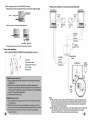
(7)How to install CM-06DNslCM-06DNs4 door station,
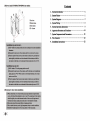
Contents
1, System Introduction
2, System Pleture-:
1
3, System Diagram
2
<DBottom frame
4, System Wiring
3
®Door station
<1'>3 x 8 screw
S, System Operation Instruction.. ····
9
(])Iron door
6, Apparatus Structure and Functions.. ··········
7, System Components and Parameters8, Wire Matertat-
9, Installation Instructions······
Installation steps on iron door:
(I )Drill 4 holes at the proper position on door according to the correct installation
dimension,
(2)Dismantle the hack cover of door station and fix it on iron door hy screws.
(3)From the npside ofhack cover pnt door station in hack cover, pnsh the door
station tightly in the hack cover from downside of door station, and fix the
door station to the hack cover at downside of door station hy screw of 3 X 8.
Installation steps on wall:
(I )Drill 4 holes of <!> 6 at the proper position on wall.
(2)Dismantle the hack cover of door station, and fix the hack cover by additional
plastic pipes and <!> 4.2 X 40mm screws on wall install the back cover of door
station on wall first.
(3)From the npside ofbeck cover put door station in back cover, pnsh the door
station tightly in the back cover from downside of door station, and fix the
door station to the hack cover at downside of door station by screw of 3 X 8.
(8)Cautions for door station installation,
(I )When emhed back cover of door station, please pay attention to depth ofbeck
cover, which should be embedded on door or wall. The outside part of door station
shonld be tightly elose to the horizontal snrface of door or wall, large interval
between door station outside part and iron door or wall shonld be avoided.
(2)000r station shonld be mouoted flush on burgiar gnard door.
(3)00 not instali under rain, moist, high temperatore, dnsty or caustic conditions.
(5)Instal1ation height:depends on the average statore ofthe local people.
><
······1
···············14
21
22
······22
(5)How to install CM-06DNk door station installation:
CD
1.The system can support two door stations and up to four indoor phones.
2.Intercom functions is available between indoor phones
3.Various indoor phone styles are applicable. Audio indoor phone WL-06DNRH is
compatible for economic purpose.
4.Door stations are with 1/3' CCD camera or CMDS camera, and built-in infrared LED
that ensures clear images at night.
5.Various door station styles are applicable.
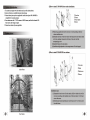
CDIron door
@Frame
®Door station
®Screw
(1)Please dig a quadrate hole on the iron door or wall according to the door
station installation size.
(2)Dismantle the frame ofthe door station's shell and put the door station inside
to the hole, making it close-knit 10 the body of iron door with the
accompanying screw.
(3)Install the frame 10 the door station.
(4)Installation height:depends on the average stature ofthe local people.
IDre
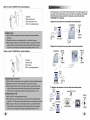
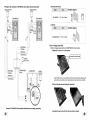
(6)How to install CM-06DNS2 door stations:
CDIrondoor
@Panel
Indoor Phone
®Backcover
®Screws
Installation steps:
(l)Dismantle the back cover ofthe door station. Drill two holes on the wall or
iron door according to the installation size ofthe door station. Fix the back
cover with screws.
(2)Take the panel tipsily and then put it on the back cover. Fix it with a screw
from the bottom.
Door Station
>
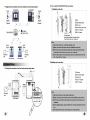
(3)How to install CM-06DNS7 door station installation:
CD
lagram
The based capacity is one door station with one indoor phone. The maximum capacity is two
door stations with four indoor phones. Users can use this system according to their demands.
CDlronDoor
®Door station's panel
®Door station's back cover
@M3X 10 anti-dismantle screw
(Note: Iftwo door stations are used for two entrances in a same villa, the switch
CM-06DNQH-N-N is requlred.)
1.Diagram for the connection of one door station and one indoor phone:
:ps-6K:
- I
it --
Installation steps:
(1)Dri1l2 holes at the proper position on door according to the correct installation
dimension
(2)Dismantle the back cover of door station and fix it on iron door by screws.
(3)From the upside ofback cover put door station in back cover, push the door station
tightly in the back cover from downside of door station, and fix the door station to
the back cover at downside of door station by anti-dismantle screw of M3 X 10.
0
I
I
I
I
4
-
---T-
-
-
I
I
i_~~I>to!j
{j
Electronic
lock
I
I
I
I
I
I
I
Optional
Door Station
2.Diagr am for the connection of one door station and various indoor phones:
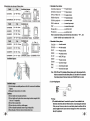
(4)How to instalI CM-06DNS6 door station installation:
CM-06DNRG
r-="
CD
Optional
I
CM-06DNRM
'-PS::6EI
I
I
I
ll ,
I
I
I
2:
:
CD Ironljoor
I
I
I
I
@bottom border
®Door station
®M3 x 10 anti-dismantle screw
: Adapter]
I
4'---_~~~_~"
4
,-
7
i
0/
Installation steps on iron door:
(1)Dri1l2 holes at the proper position on door according to the correct installation dimension.
(2)Dismantle the back cover of door station and fix it on iron door by screws.
(3)From the upside ofback cover put door station in back cover, push the door station
tightly in the back cover from downside of door station, and fix the door station to
the back cover at downside of door station by anti-dismantle screw of M3 X 10.
Door Station
3. Diagram for the connection oftwo door stations and one indoor phone:
PS-2E
(1)Dri1l2 holes of ep6 at the proper position on wall.
(2)Dismantle the back cover of door station, and fix the back cover by additional plastic
pipes and ep4.2 X 40mm screws on wall install the back cover of door station on wall first
(3)From the upside ofback cover put door station in back cover, push the door station
tightly in the back cover from downside of door station, and fix the door station to
the back cover at downside of door station by anti-dismantle screw of M3 X 10.
Adaptor(DC 14-18V)
Power 2 , •
Installation steps on wall:
©
~ ~ ~ ~ III~~~
Optional
--PS-6E :
lJ
Electronic
lock
.~-
4
I
I
:
I
I
I
I
I
i_~~I>to!j
(2) How to instaU CM-06DNG2/DNG2A door stations:
4. Diagram for the connection of two door stations and various indoor phones:
CM-06DNRI
CM-06DNRV
'-PS::6EI
I
I
I
I
I
~"., ,"'''"
I
I
CDInstallation on the waU:
,
~
I
I
I
I
I
I
I
I
:I Adapter]
J
4
4
Optional
}
7
Adaptor
(DC14-18V)
15
I'
CDWall
Q)Door station's panel
®Front cover
®Door station's back cover
®FA2.8 x 18 screw
®M4 x 45 screw
glue the cement
around the hole about 15mm hick to fit the
Door station's back cover on the wall
Electronic
lock
4
4
•
•
Door Station
1111-7'-_ ---'
Step:
(l)Take out the front cover, main body and back cover.
(2)Make a hole on the wall base on the size ofinstallation on the wall .
(3)Put the back cover inside the wall and glue the cement around the hole about
15mm hick to fit the Door station's back cover on the wall.
(4)See the above picture to fit the main body ,front cover and the back cover with
M4 x 45 and FA2.8 x 18 screw.
©
Electronic
lock
Door Station
® InstaUation on the iron door :
iring
l.Wiring for the connection of one door station and one indoor phone:
r-';.-CD
CDIron door
Q)Door station's panel
®Front cover
®FA2.8 x 18 screw
®M4 x 45 screw
AUDIO
II I--------------------------~ 'I
I I
::
I I
1 1
rc=;::::~~~~
CM-06DNRMi:
®
Adaptor
orPS-6E
I '
®
Step:
=0=
Door Station
(l)Take out the front cover, main body and back cover
(2)Make a hole on the iron door base on the size of installation on the iron door.
(3)On the front size ofthe iron door make two holes, the size of the hole see our
instruction.
(4)See the attached picture, use 2pcs M4x45 screw to fit the main body to the iron
door.
(5)Use 4pcs FA2.8x18 screw to fit the front cover on the main body.
>
(2)How to change name label for CM-06DNS2/S6 door station:
Insert the screw driver into the groove from one of two sides of the name plate.
*
2.Wir ing for the connection oftwo door stations and one indoor phone:
Door Station 2
0= .
=
.
Door Station 1
~~ J©
~~
Power
.
* Press the screw driver and take offthe glass plate.
.
11
- - ,. ,-t-"
Cl
®
1<1
0=
.=
I·
Power
~
©l
~
Electronic
lock
.
Electronic
lock
1
/®
--" ,-+-"
~R)
l{ \
)
11
11
11
11
11
11
11
AUDIOffilue)
VCC(Red)
1!c_______ (}@((Jr~enl __________ J :
J
VIDEO(Yellow)
glass plate
* Assemble the parts contrarily after the name label is changed.
~
»-> ,-_
o
Adapto
(DC14-18V)
3.Door station installation:
(l)How to instaU CM-06DNdllCM-06DNd2 door stations(without rain cover):
@
AUDIO(Blue)
CDIronDoor
®Door station's panel
@Door station's back cover
@4X45 screw
@Small cover
11
@
I
VCClRed)
CM-06DNQH-N
Switch
11
: l_____q~«(Jr~I1L ___ _r
l ___________
g
(1)Drill a reetangular hole on proper position of the wall according to door station
on installation size.
(2)Drill four CI> 6 holes as the door station installation size on the groove. Fix the
back cover on the groove with the attached plastic tubes and screws (4.2 x 40mm)
(3)Press the front cover on the back cover, then use 2 M4 x 25 inner hexagon
screws to lock them.
@ (D~V)
D
~
P
Installation steps on iron door:
Installation steps on wall:
~
0
e
(l)Drill a reetangular hole on proper position ofthe iron according to door station
installation sizw.
(2)Pull out the two small covers. Take offthe screws with the attached inner
hexagon wrech, and then take offthe door station back cover. Fix the back cover
on the iron door. Then lock the door station from the back cover with the attached
two M4X25 screws and fixed steel sheet.
(3) Push the small covers and firm it.
Adapto r
CM-06DNRV2
@
VIDEO(Yellow)
IT
@ i!;
0
CJ
CI
AUDIO
vCC
11
11 ___G~D
1
VIDEO
~
F.r D
@ ~AVT
0 +18Y
DY GND
i§1 Ei
I I~
11
11
11
I1
11
1
11
--' 1
Cl
....,. Black
F=
,,1'-:
AUDIO
D
,-----
vcc
L~
GNU
VIDEO
COM
NO
+ISV
db
G
~
-
~
7
Notes:
(1) When the distance is not less than 30 meters between door station and indoor phone, the
specific resistor should be connected between VIDEO and GND terminals ofthe indoor
phone. If more indoor phones are used, the specific resistor should be connected in the
same position ofthe last indoor phone.
(2) When the distance is more than 50 meters, a video cable is required. The core ofthe video
cable should be connected 10VIDEO terminal and the shielded not wire should be
connected to GND terminal on both door station and indoor phone.
3. Wiring for tbe connection of CM-06DNG2A door stations and one indoor pbone:
Adaptor{DCl4V)
Adaptor(DCl4V)
(lO)Audio indoor pbone:
Mode
WL-06DNRH
Size
fu_~
a
94 x 216 x 59mm
~
0 0
(ll)Switcb:
Mode
Size
Installation diagram:
-
,
~~
<r "
CM-06DNQH-N 91 x 80 x 21.5mm
'f
cl:
• ---
.s>:
I
I
I
I
I
I
I
<r "
-~
,--
2.How to change name labels
(1)How to change name labels on CM-06DNd2/G2A door stations:
I I
I I
* Dismantle tbe back cover of door station.
VIDEO(Yellow)
Dll!~:----"""/
Around the circuit board
D Adaptor
(DC14-l8V)
@
@
CM-06DNQH-N
Switch
CM-06DNRV2
@
Take offthe screws on circuit board with screw driver. Insert and press the
screw driver around the circuit board and move the board very carefully.
VIDEO(Yellow)
* Take out tbe glass plate and cbange tbe name label.
@
@
,L
I
~~~~_·_r_r_~i~i~~I!~~J.~~~
AUDIO
__
I
-------------~~o-----~
Remark: CM-06DNG2A door station sbould add apower supply separately.
* Assemble the parts contrarily after the name label is cbanged.
>
3. Terminals of door stations:
(9)Installation size and map of indoor phone:
Model
CM-06DNRG
Size
222 x 200 x 66mm
Installa~~~~m:
12mm
~M 0
~ ~
~
CM-06DNRH-M 224 x 218 x 57mm.
Model
Size
~
o --"- ~
0
o
0
CM-06DNRH-M Holder CM-{)6DNRG Holder
In8tall~tion ~~
120mm
~.,~~
CM-{)6DNRM
210 x 220 x 56mm
CM-{)6DNRI
235 x 200 x 40mm
CM-{)6DNRV
250 x 224 x 53mm
CM-{)6DNRV3
185 x 120 x 34mm CM-06DNRMII/V Holder
:D~1
0
~
Model
CM-{)6DNRL
Size
100 x 210 x 32.5mm
- .I
-
Ins~~.:~e:
L0=
00
D
0
o
OeJ
, "c
,00 tri
u--r
CM-{)6DNRV2
260 x 234 x 47mm
CM-{)6DNRV6
214 x 171 x 32mm CM-06DNRL Holder
0
c
r=
,~
CM-Q6DNRVIN2N6
Installation diagram:
~
ff,"
l~
6~
-,--'-
-
I
• video terminal
(l)VCC or Yellow wire
• anode terminal
OOGND or Red wire
• cathode terminal
(l)COM or purple wire
• common output
®NO or white wire
• normal open output
(DNC
• uoruta1 close output
®Lock+(LK+)
• electronic lock
®Lock-(LK-)
• electronic lock
LOCK+ I LOCK- may he marked as LK+ I LK-.
4. Terminals of indoor phones:
(j)AUDIO
• •udio terminal
(J)VIDEO
• video terminal
(l)VCC
• anode terminal
OOGND
• cathode terminal
(l)+18V
• DCl8Vinput
®GND
(DCOM
• anode terminal
®NO
-', I
~~
-----I.~common
output
---.~normal open
®NC
-----I.~ normal
output
close output
Note: COM, NO and NC terminals of indoor phon.. are for the purpose that the
locks are connectedfrom the indoor phones. 2) Locks have to be connected
from indoor phones if the door stations are CM-06DNK (b/w or color).
~
Installation steps:
(I)Fix the holder on a suitable position on wall with 4 screws as the Installation
diagram.
(2)Hang up the indoor phone on the holder.
Cautions:
(1)00 not instalI near moist place and burner,
(2)00 not instalI near the place where causes s1rongelectrionic magoetic field.
(Such as TV loudspeakor).
(3)00 not fall or punchy strike.
(4)00 not clean by wet cloth or volatile reagent.
(5)DO not dismantle optionally, because ofhigh voltage inside.
(6)Keep the glass ofthe door station and indeor phone clean.
><
(J)VIDEO or Green wire
CM-06DNRV3
I6
220 x 150 x 25mm
• •udio terminal
Note: In some door stations, anode terminal may be marked as "VD" . And
0 0
f-- 120mm-------1
CM-{)6DNRVI
(j)AUDIO or Black wire
5. Lock wiring diagram:
WCK
Warning:
l)The defanlt unlock time is 5 second in the system.lt is not suitahle for the
eleetrouic controllocks that are withont motors. It may damage the said loeks
if they are used. In ease yOD have to use such locks, please du eeaflrm with the
product supplier that the system hai been changed to be with 1 seeend unleek
time hy the producer.
2)If use electronic controllocks that are without motors, reverse diodes have to be
connected with two ends of the winding of the locks (as the ehart), The producer
recommends IN4007 reverse diode.
(7)CM-06DNS7 Door Station:
<D Outside size: 58.1 x 135.1 x 48.1mm
@Installation dimension: 60mm
48.
6. CM-06DNQH-N switch terminals:
(8)Power supply:
(l)To door station 1 ( 4-cord cable)
<DAUDIO(Blue)
~
Audio terminal (to door station No.l)
@YCC (Red)
~
Anode terminal (to door station No.I)
®GND(Green)
~
Cathode terminal (to door station No.I)
@YIDEO(Yellow) -----. Video terminal (to door station No.l)
(2)To door station 2 (4-cord cable)
<DAUDIO(Blue)
~ Audio terminal (to door station No.2)
@YCC(Red)
~
Anode terminal (to door station No.2)
®GND(Green)
~
Cathode terminal (to door station No.2)
Model
Installation size:
Size
~- C·
5Omm
PS-5A-3
283 x 189 x 71mm
PS-5E
124 x 90 x 70mm
PS-6E
74 x 90 x 63.5mm
PS-6E installation diagram:(l)
.
.
0
WO
::
0
e
PS-5A-3
o
oo
PS-5E
Io'oIT~
0
@
PS-6E
PS-5A-3(UPS) installation diagram:
@YIDEO(Yellow) -----. Video terminal (to door station No.2)
(3)To indoor phones (4-cord cable)
PS-6E installation diagram:(2)
<DAUDIO(Black wire)
~ Audio terminal
@YCC(Greenwire)
~ Anode terminal
®YGND(Yellow wire)
~ Video cathode terminal
@YIDEO(Redwire)
~
Video terminal
~ (u})
Accessory:
-
~t
~L
.
,
,
L
,
~
~-h--'---r-'-
fI--
Slip buckl
I
-
SPring
Step®
Self-buy acessory:
_ _ Utype
guideorbit
Installation steps division:
Stepl .....
(E/ALNS 35)
~
Step2 ......
Step3 ......
Press down 10 draw the slip buckle
- - 4x40screw
(OB 99-86)
(2)Installation size of G2 erust door station:
1
1
1
1
1
1.d-1 ~L",
i
TI
_. -f-_._._._._._.j_._ . .
2-M4~
~ .~_ . -
.1. "
·· f
Power Supplies
_.N
11
I
-~. . .~__""DC+18V For video
Adaptor
-~III.~""''''''DC+14V Forswitch
indoor phone
I
I
I
I
I
Installation size on wall
Door station
size(mm)
Installation size on
iron door (mm)
Installation size
on wall (mm)
145 x 135 x 89
11O(L) x 109(W)
135(L) x 125(W) x 65(D)
CM-06DNG2A 262 x 135 x 89
227(L) x 109(W)
252(L) x 125(W) x 65(D)
CM-06DNG2
Adaptor
"\I{
Installation size on iron door
Model
7. Power supply:
The system is powered from indoor phones. There are three kinds ofpower supp1y:Adaptor,
transformer (pS-6E, PS-5E) and built-in power inside indoor phones. CM-06DNRI-N,
CM-06DNRH-N and CM-06DNRJ-N are with built-in power.
(3)CM-06DNS IS4 Door Station:
CDOutside size: 100 x 140 x 43mm
@Installation dimension: 60 x 100mm
100mm
O~
CM-06DNQH-N
GND
(4)CM-06DNK Door Station:
CDOutside size:85 x 125 x 53mm
@Installation dimension:50 x 68 x 36mm
85mm
48mm
PS-6E
transformers
......,.....,....
I • • • • • •• • • •• ,.
............,.
• ••• '1 . . . ,.1 ,1
~
Formemory
PS-5E
transformers
(5)CM-06DNS2 Door Station:
CD Outside size: 126.2 x 92.2 x 30.5mm
@lnstal1ation dimension: 85mm
Forvideo
indoor phone
CM-06DNRH-M
(6)CM-06DNS6 Door Station:
CDOutside size: 76 x 118 x 29mm
@Installation dimension: 685mm
29
PS-5A-3
Power
Supp1y
Formemory
PS- 5A- 3 POWER SlPPl Y
r5 - 5'\- 3 POWER SUrrLY
A~ i nput nl)v: : ~
DCout put clß VI3 A
AL I nput . l W(: : ~
Prot ect i oo Grade : IP3Q
Protect iooG'ade : ,PlO
CM-06DNRH-M
X out put : 10 'l/3A
Notes: The memory indoor phones CM-06DNRH-M have to use PS-5E transformers or
PS-5A-3 power boxes. PS-5A-3 power boxes have battery inside that can ensure
powering the system in case the exterior power is cut. so that the memorized images
can be reserved. But PS-5E transformers have not. Once the exterior power is cut,
the memorized images will all disappear.
>8
?,
"1\
.Jlli ~ "
: tion Instruction
l.Call and answer
Power supply I
_
l:
a)Input voltage: AC230V ± 10%
-_
b)Output voltage: DCI8V/800mA(Adaptor/PS-6E/PS-5E) -_
_
DCI8V/3A(PS-5A-3)
(C r---1.1 When avisitor pushes the call button on the
door station, the indoor phone will ring and the
screen shows the visitor's image. The host can
pick up the handset (ifhand-free indoor phone
please push TALK button instead) to answer the
call. The conversation is allowed in 120 seconds.
Ifnobody answers the image will disappear in 30
seconds.
_
.
_
.
l.If the transmitting distance is ~ 50 meters, RVV 4 X 0.5 or larger size copper core
multi-sector wire is required among systems.
2.Ifthe transmitting distance> 50 meters, 75-5 video wire is required. Wires for other
purposes, RVV2 X 0.5 or larger size copper core multi-sector wires are adopted.
on Instructions
1.Installation size:(L=aluminum alloy cover length)
~
Dl
o
Installation size on iron door
~AI
Installation size on wall
(l)lnstallation size table for aluminum alloy door station series:
1.2 During the conversation status the host can push
Unlock button 10 open the door for the visitors.
Model
Cover length Door station
L(mm)
size(mm)
Installation size on
iron door (mm)
Installation size
on wall (mm)
CM-06DNdl
138
174 x 130 x 52 166(Ll) x 108(WI) x 38(DI) 164(L2) x 126(W2) x 42(02)
CM-06DNd2
180
216 x 130 x 52 208(Ll) x 108(Wl) x 38(Dl) 206(L2) x 126(W2) x 42(D2)
Note: Iftwo door stations are used in the system, the indicator ofCM-06DNQH-N-N
switch will turn on to red when call from door station No. 1 (button backlight
of door station No. 2 turns off at this moment) and turn on to green when caU
from door station No. 2 (button backlight of door station No.l turns off at
tbis moment),
Remark: While there are noisy around, conversation via hand-free indoor
phones may be disturbed lightly. It is normal.
>
JE0Tl "
I
I
onents and Parameters
06DN Series Door Station I
a)Working Voltage: DC 12V ± 10%
--_
.. --_ .. --_ .. --_ .. --_ .. --_ .. --_ .. --_ .. --_ .. --_ .. --_ .. -_ ... -_ ... -_ ... -_.
b)Static
Current: "12mA
.........................................................................
c)Working
Current: "180mA
--_
.. --_ .. --_ .. --_ .. --_ .. --_ .. --_ .. --_ .. --_ .. --_ .. --_ .. -_ ... -_ ... -_ ... -_.
d)Camera: 113'CCD or CMOS(B/W or color); View angel:92.8°
--_ .. --_ .. --_ .. --_ .. --_ .. --_ .. --_ .. --_ .. --_ .. --_ .. --_ .. -_ ... -_ ... -_ ... -_.
Min.1uminance=O.lLux; Lens:F=3.6
.........................................................................
Pin hole camera : 1I3'CCD or CMOS(B/W or color);(for pin hole door station)
.........................................................................
Min.1uminance:
Lens angle:87° ; Lens:f-=3.7mm/f-=2.0
--_ ..
--_ .. --_ .. --_ 0.05LuxlF1.2;
.. --_ .. --_ .. --_ .. --_ .. --_ .. --_ .. --_ .. --_ .. --_ .. --_ .. --e)Environment Temperature: -25 - +70"C
.........................................................................
t)Humidity: 45% - 95%
Indoor Pbone I
a)Working Voltage: DC18V ± 10%; AC100-240V 50-60Hz(for CM-06DNRH-N)
--_
.. --_ .. --_ .. --_ .. --_ .. --_ .. --_ .. --_ .. --_ .. --_ .. --_ .. -_ ... -_ ... -_ ... -_.
b)Static
Current: "50mA; "135mA(CM-06DNRH-M); "IW(CM-06DNRH-N) .
.....
c)WorkingCurrent:
.;;; 700mA; .;;; 800mA(CM-06DNRH-M); "15W(CM-06DNRH-N)
--_
.. --_ .. --_ .. --_ .. --_ .. --_ .. --_ .. --_ .. --_ .. --_ .. --_ .. -_ ... -_ ... -_ ... -_.
d)Kinescope: 4' flat tube(black/white); Resolution>450 lines;
--_
.. --_ .. --_ .. --_ .. --_ .. --_ .. --_ .. --_ .. --_ .. --_ .. --_ .. -_ ... -_ ... -_ ... -_.
display: 4' color LCD display ; Resolution:480 x 250 points;
--_ Color
.. --_ .. --_ .. --_ .. --_ .. --_ .. --_ .. --_ .. --_ .. --_ .. --_ .. -_ ... -_ ... -_ ... -_.
e)Environment Temperature: -10 - +55 "C
--_ .. --_ .. --_ .. --_ .. --_ .. --_ .. --_ .. --_ .. --_ .. --_ .. --_ .. --_ .. --_ .. --_ .. --t)Humidity: 45% - 95%
Hand-Free Indoor Phone I
a)Working Voltage: DCl8V ± 10%; ACIOO-240V 50-60Hz(for indoorphonewith built-in SMPS)
--_
.. --_ .. --_ .. --_ .. --_ .. --_ .. --_ .. --_ .. --_ .. --_ .. --_ .. -_ ... -_ ... -_ ... -_.
b)Static
Current: " 60mA; " 1.2W(for indoor phone with built-in SMPS)
--_
.. --_ .. --_ .. --_ .. --_ .. --_ .. --_ .. --_ .. --_ .. --_ .. --_ .. -_ ... -_ ... -_ ... -_.
c) Working Current: ~500mA; ~ 15W (for indoor phone with built-in SMPS)
.........................................................................
d)Color display: 2.5'/4'15'1 5.6'color LCD display; Resolution:480 x 250 points;
--_
.. --_ .. --_ .. --_ .. --_ .. --_ .. --_ .. --_ .. --_ .. --_ .. --_ .. -_ ... -_ ... -_ ... -_.
: 4' flat tube(black/white); Resolution>450 lines;
--_ Kinescope
.. --_ .. --_ .. --_ .. --_ .. --_ .. --_ .. --_ .. --_ .. --_ .. --_ .. -_ ... -_ ... -_ ... -_.
e)Environment Temperature: -10 - +55"C
--_ .. --_ .. --_ .. --_ .. --_ .. --_ .. --_ .. --_ .. --_ .. --_ .. --_ .. --_ .. --_ .. --_ .. --F)Humidity: 45% - 95%
Switch
I
2.Surveying entrances
2.1 Push MONITOR button, the host can survel the
entrance situation. Ifwant 10 close the screen
please just push it again. The surveillance can
keep 30 seconds. During surverying the host can
talk with outside visitor's by picking up the handset
(ifhandfree indoor phone ,push TALK button instead)
2.2 Ifthere are two door stations, the survey for
different entrances is available by turns. Ifthe host
wants to survey another entrance after he/she
finishes the survey for the first entrance, he/she
has to push MONITOR button again in 10 seconds.
3.Intercom between indoor phones
3.1 if there are not less then two indoor phones,
intercom is available between the indoor phones .
Push CALL button in any of the indoor phones
(1st indoor phone), the other indoor phones will
ring together at the same time. Anyone picks up
the handset (ifhand-free indoor phone please push
TALK button instead) of any other indoor phone
(2nd indoor phone) to answer, the other indoor
phones (3'" indoor phones) will stop ringing. At
this moment pick up the handset (ifhand-free
indoor phone please push TALK button instead)
of the l" indoor phone, intercom is available
between the 1st and 2nd indoor phones. Conversation
time is not limited. [Note: ifyou pick up the
handset before you pusb CALL button, tbe 3'"
indoor phone(s) will not stop ringing until tbe
ring time is up even if tbe 2"" indoor pbone
answers tbe call.]
Note: It is normal for the system to ring but appear no image after powered
at tbe first time.
a)Working Voltage:DCI4-18V ± 10%;
.. --_ .. --_ .. --_ .. --_ .. --_ ... -_ ... --_ .. --_ .. --_ .. --_ .. --_ .. --_ .. --_ ... -_.
b)Static
Current.X 50mA
_ .. --_ .. --_ .. --_ .. --_ .. --_ ... -_ ... --_ .. --_ .. --_ .. --_ .. --_ .. --_ .. --_ ... -_.
c)Working Current: " 120mA;
_
@<
>
Operation instructions of MEMORY indoor phone
... CM-06DNRV3 Indoor phone
I.Manual!Auto button:
The button is a switch. The memory function can be turned on/offby pushing it.
The default is auto status (the indicator is on). Every time a visitor calls, the indoor
phone will record an image (the same when surveying). Ifyou don't want to record
images, please turn it offby pushing the button.
,--------+- ®
®
®
®
@--@----
®-@--
®--
2.Display:
@---~
When the RECORD indicator is on, that tells there is no read image. While the screen
works and push DISPLAY button, users can read the image. The display time is 5
seconds. Ifusers do not read the next images by pushing DISPLAY button, the display
will elose in 5 seconds.
3.Adjust:
Push MONITOR button to switch on the screen. Push ADJUST TIME button, then the
minute position will flash. At this moment push DISPLAY button and you can adjust
the minutes. Push ADJUST TIME button again, then the hour position will flash. At this
moment, push DISPLAY button and you can adjust the hours. The rest like year, month
and day may be deduced by analogy. (Note: Numbers cannot be reduced while
adjusting.)
4.Memory capacity
- - - - - - - - --=......
~ (DDisplay
~ ®Talk Indicator
IDisplays visitor's image
~ ®Loudspeaker
Indoor phone voice comes out
fromhere
~ ®Talk Button
Press the button can talk with the
callin side
@
@
@
(j)
Press "Talk" button,light on or off
~
(@Ring type
IRing: three options
~ @Brightness Adjuster
The memory capacity is up to 32 images. Ifthe image quantity is over 32pcs, the latest
images will cover the oldest images, one by one. That means image No. 33 will cover
number I, No. 34 will cover No. 2. The rest may be deduced by analogy.
IBrightness Adjuster
~
~ @Call Button
Press this button for internat
broadcasting call
~ @Monitor Button
Press this button to supervise
door station
~ (j)Unlock Button
IDuring conversation press it to
@Chroma adjuster
IAdjust contrast or chroma
~ @RingVolumeAdjuster
IAdjust the ring volume
~ @Talk Volume Adjuster
IAdjust the conversation volume
unlock
~ @Power Indicator
IPower works while it is on
~ ©Microphone
ITalk to door station
.... Video Indoor Phone(hand-free)
1- -CM-06DNRVI
- - - - -- - - - @®
®
CD
CM-06DNG2A door station with card reader
CD-+-t-.-@
@
®
®
(@
@
@
@
@
~
®
®
®
Inside structure
~ CDDisplay
~ @Talk Indicator
IDisplays visitor's image
Press "Talk" button,light on or 0
~ @Loudspeaker
Indoor phone voice comes out
fromhere
~ ®Talk Button
Press the button can talk with the
callin side
~ @Call Button
Press this button for internal
broadcasting call
~
@)Busy Indicator
IBusy while it is on
~
@Microphone
ITalk to door station
~ @Brightness Adjuster
~ ®Monitor Button
IBrightness Adjuster
Press this button to supervise
door station
~ ®Unlock Button
During conversation press it to
unlock
~
(1)Mute Button
While there is noisy at the door
station, press it to keep visitor's
voice only.
~ @Power Indicator
IPower works while it is on
~
@ContrastiChroma adjuster
IAdjust contrast or chroma
~ @RingVolumeAdjuster
IAdjust the ring volume
~ @Talk Volume Adjuster
IAdjust the conversation volume
I.Login the ID cards: Open the back cover ofthe door station(see the above picture), press
the " Login" button, the indicator turn green, it means that it is on the login status. Close
the ID card to the telepathy area, the indicator turn yellow and hear a long indicate sound,
it means that the ID card login succeed. Ifyou hear two short sound, it means that the ID
card was login already before or the deposited is full. You can elose the different cards
continue, then press the " Login" button again to exit the login status.
(Remarks: (1) it can login 30 pcs ID cards at most.
(2)How to separate the ID card was login already before or the deposited is
full: When you hear two short sound, try to login other ID card continue,
if it comes two short sound again, it means that the deposited is full, but if
it can login other ID card succeed, it means that the ID card was login
already before.)
2.Logout the ID cards: Press the " Logout" button, the indicator turn green, it means that it
is on logout status. Close the ID card to the telepathy area, the indicator turn yellow and hear
a long indicate sound, it means that the ID card logout succeed. Ifyou hear two short sound,
it means that it is a new cards and still have not login. Press " Logout" button again to exit
the logout status.
3.Cancel an the ID cards message, please do as following step:
CDTum offthe power.
@Open the back cover and inner cover(see the attached picture), connect the pin to DEL
terminal on ffi2.
® Tum on the power.
® Tum offthe power again, return the pin to NO terminal again.
® After finished the above steps, all the original message was cancel.
T Video Indoor Phone(hand-free)
D
Pin
NO DEL
CM-06DNRV
CM-06DNRL
Short circuit
::~:mm:mm~~~:::
@
NO DEL
[g::::]
c:::::J:'5J
Short circuit on DEL
Short circuit on NO
Inside structure
On the following condition, we can choose to cancel all the original message:
(l)The quantity ofthe ID cards are too many for a system(full enough).
(2)Some original ID cards were loss or damaged, which can't be logout.
(3)When you like to cancel all the original ID cards.
4.Setting the unlock time(! second or 5 second): Open the back cover and inner cover(see the
attached picture). On the JB 1, there are 1 second and 5 second for selection. Turn the pin cap
to different size can select the unlock time.
~CDDisplay
short circuit
18 58
[g::::]
c:::::J:'5J
1 second
for selection
5 second
for selection
5.Volume adjust: Open the back cover and the inner cover( see the attached picture) ;
M-----~I
Inside structure
IAdjust brightness
~ @ContrastAdjust
IPress this button to survey entrance I
~ @UnlockButton
IAdjust contrast
~ @Ring Volume Adjuster
During conversation press it to
unlock
Inside structure
I[~]I
~ @)Brightness Adjust
Indoor phone voice comes out
fromhere
~ ®Monitor Button
18 58
IPress "Talk" button,light on or offl
IDisplays visitor's image
~ @Loudspeaker
Pin
~ ®Talk Indicator
G G
MIC
SPK
MIC: Adjust the volume ofMIC
SPK: Adjust the volume of SPK
~ ®Call Button
IAdjust the ring volume
~ @Talk Volume Adjuster
Press this button for internal
broadcasting call
IAdjust the conversation volume
~ ®SiIence Button
While there is noisy at the door
station, press it to keep visitor's
voice only.
~ (1)Ring Beils Adjuster
~ CVTaik Button
~ @Movable Cover
Three melody are optional
(not for ding-dong ring)
Press the button can talk with the
calling side
~ @Power Indicator
IPower works while it is on
IMovable, usage inside
~
@Microphone
ITalk to door station
.... Video Indoor Phone(hand-free)
CM-06DNRI
.... Door Station
CM-06DNRV6
@
® -+-.::. '. . . .@)-
@-,
@-
@--
CD
©
®
@
@
@
(J)
®
@
~:ij ~
~---
@
I Display visitor's image
~ ®Microphone
I Talk to door station
I Press "Talk" button,light on or o~
~ <®Brightness Button
~ ® Loudspeaker
I Indoor phone voice comes out from here I
_ t--'itl---CD
~ ®Talk Indicator
-{:2
~
['----------tE---~
~~------{6
~ @Microphone
CM-06DND2
I Talk with indoor phone
~
I Use this button to adjust brightness I
~
~ ®Call Button
Pick up the handset, Press this
button for internal call
~ @Monitor Button
Press this button to survey
entrance
~ C:VUnlock Button
During conversation press it to
unlock
~
@Power Indicator
I Power works while it is on
@Power Indicator
I Light will be on all the time
~ @ContrastiChroma Button
~ ®Name plate
Use this button to adjust contrast or
chroma
@Uni-talkButton
While there is noisy at the door
station, press it to keep visitor 's
voice only
@CaUbutton
I Press this button to call indoor phone
~ @Talk Button
Press the button can talk with the
calling side
CDCameraIPin hole camera
Built-in infrared LED (not for pin
hole camera)
@
CM-06DNDl
___ ~_ffi--
~ (1)Display
~
I Hostname
CM-06DNG2A
~ (J)LED sensor
~ @Ring Volume Adjustor
Automatically control LED according
to illumination
I Adjust the ring volume
~
~ @Talk Volume Adjustor
I Adjust the conversation volume
rr::~~,@
IH+:-+--'®
~@Ringtype
I Ring: three options
I++trt-H-C1--- 1
CD
I
1..I.:.::] (""tt+ - -@
~:::::::::::~-,@
@Name card areal Card reader area
I Name card area/Card reader area
~
I
® Indicator
Normal status is red,
setting status is green,
card reading status is yellow
CM-06DNS2
-F=::;-- (J)
@
CD
~ @Movable Cover
@
@
'""-"~""----CD
- l=::::::'_ ®
®
Indoor phone voice comes out
fromhere
CM-06DNS4
CM-06DNK
CD
®
(f)
~---'L.C'-----(f)
@
'--------@
CM-06DNS6
®
:C+ if-EioOl:lS--
CM-06DNS7
@
I
I@
T Video Indoor Phone(handset)
T CM-06DNRH-M Memory Indoor Phones
CM-06DNRM
CM-06DNRG
@-
...--(;N-
@--
--+....:,:-- (D
@-
QJ)
@ @-
@
----@
-~ (1)
CD
@--
®
@-
@
j..-/@
..
I
I ~~----i- ®
~ CDDisplay
Displays visitor's image
~ CDDisplay
Display visitor's image
Press this button to supervise
situation of entrance
~ ®CaU Button
ick up the handset, Press this
utton for internal call
~ @UnlockButton
During conversation press it to
unlock
~@Handset
I Used to talk to caller
~
(7)Adjust time Button
I For adjust date and time
~ @Talk Indicator
Press "Talk" button,light on or off
~ ® Monitor Button
Press this button to survey entrance
~ ®Monitor Button
I
@@
~ (f)Power Indicator
IPower works while it is light
~ ® Call Button
Pick up the handset, Press this
button for Internal call
~ ® Brightness Button
Use this button to adjust brightness
Contrast Button
~ ® Contrast Button
Press this button to adjust contrast,
~ ®Brightness Button
~
Use this button to adjust brightness
@Unlock Button
During conversation press it to
unlock
~ ®lHandset
I Used to answer the call
~ ®Contrast Button
~
Use this button to adjust contrast
@Manual-Auto Button
Press this button for video
record / termination ofvideo record
@ Manual-Auto Indicator
Indicator lights under automatie
model;
Indicator is offunder manual model.
~ @)Ring Volume Adjuster
~ @Display Button
I Adjust the ring volume
Press this button to display images
@Record Indicator
Indicator lights, means that
there are un-read images