1
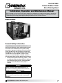
Part #473380 Grease Grabber™ H2O Auto-Cleaning Hood ® Installation, Installation, Operation Operation and and Maintenance Maintenance ManualManual Please read and save these instructions. Read carefully before attempting to assemble, install, operate or maintain the product described. Protect yourself and others by observing all safety information. Failure to comply with instructions could result in personal injury and/or property damage! Retain instructions for future reference. Model GGH2O General Safety Information Only qualified personnel should install this unit. Personnel should have a clear understanding of these instructions and should be aware of general safety precautions. Improper installation can result in electric shock, possible injury due to coming in contact with moving parts, as well as other potential hazards. Other considerations may be required if seismic activity is present. If more information is needed, contact a licensed professional engineer before moving forward. 1. Follow all local electrical and safety codes, as well as the National Electrical Code (NEC), the National Fire Protection Agency (NFPA), where applicable. Follow the Canadian Electric Code (CEC) in Canada. DANGER Always disconnect power before working on or near a unit. Lock and tag the disconnect switch or breaker to prevent accidental power up. CAUTION When servicing the unit, motor may be hot enough to cause pain or injury. Allow motor to cool before servicing. 1 Model GGH20 Grease Grabber Auto-Cleaning Hood ® Receiving Upon receiving the product check to make sure all items are accounted for by referencing the bill of lading to ensure all items were received. Inspect each crate for shipping damage before accepting delivery. Notify the carrier if any damage is noticed. The carrier will make notification on the delivery receipt acknowledging any damage to the product. All damage should be noted on all the copies of the bill of lading which is countersigned by the delivering carrier. A Carrier Inspection Report should be filled out by the carrier upon arrival and the Traffic Department. If damaged upon arrival, file claim with carrier. Any physical damage to the unit after acceptance is not the responsibility of Greenheck Fan Corporation. Unpacking Verify that all required parts and the correct quantity of each item have been received. If any items are missing, report shortages to your local representative to arrange for obtaining missing parts. Sometimes it is not possible that all items for the unit be shipped together due to availability of transportation and truck space. Confirmation of shipment(s) must be limited to only items on the bill of lading. The unit should be stored at least 3½ in. (89 mm) off the floor on wooden blocks covered with moisture proof paper or polyethylene sheathing. Aisles between parts and along all walls should be provided to permit air circulation and space for inspection. Inspection and Maintenance during Storage While in storage, inspect once per month. Keep a record of inspection and maintenance performed. If moisture or dirt accumulations are found on parts, the source should be located and eliminated. REMOVING FROM STORAGE — As units are removed from storage to be installed in their final location, they should be protected and maintained in a similar fashion, until the equipment goes into operation. Prior to installing the unit and system components, inspect the unit assembly to make sure it is in working order. Handling Units are to be rigged and moved by the lifting brackets provided or by the skid when a forklift is used. Location of brackets varies by model and size. Handle in such a manner as to keep from scratching or chipping the coating. Damaged finish may reduce ability of unit to resist corrosion. Storage Units are protected against damage during shipment. If the unit cannot be installed and operated immediately, precautions need to be taken to prevent deterioration of the unit during storage. The user assumes responsibility of the unit and accessories while in storage. The manufacturer will not be responsible for damage during storage. These suggestions are provided solely as a convenience to the user. The ideal environment for the storage of units and accessories is indoors, above grade, in a low humidity atmosphere which is sealed to prevent the entry of blowing dust, rain, or snow. Temperatures should be evenly maintained between 30°F (-1°C) and 110°F (43°C) (wide temperature swings may cause condensation and “sweating” of metal parts). All accessories must be stored indoors in a clean, dry atmosphere. Remove any accumulations of dirt, water, ice, or snow and wipe dry before moving to indoor storage. To avoid “sweating” of metal parts allow cold parts to reach room temperature. To dry parts and packages use a portable electric heater to get rid of any moisture build up. Leave coverings loose to permit air circulation and to allow for periodic inspection. 2 Model GGH2O ® Table of Contents Grease Grabber™ H2O System Function..................... 3 Cleaning Cycle Manual and Automatic Engagement......................... 4 Fire Mode....................................................................... 4 System Components Hood........................................................................... 5 Grease Grabber H2O Control Cabinet....................... 5 Graphic Keypad......................................................... 5 Unpacking...................................................................... 6 Hood Widths and Base Weights................................... 6 Installation Overview Filler Panels................................................................ 7 Back Supply Plenum.................................................. 7 Hood Hanging Height................................................ 8 Double Island Style.................................................... 8 Installing U-Channel Strip....................................... 8 Continuous Capture Plenum.................................. 8 Ductwork.................................................................... 9 External Supply Plenums...................................... 9-10 Supply Plenum Clip................................................ 9 Uni-Strut................................................................ 10 Threaded Rod....................................................... 10 Supply Duct Collar................................................... 10 UL Listed Fastener................................................... 11 Back Supply Plenum........................................... 11-12 Supply Duct Collar................................................ 11 Hanging the Back Supply Plenum.................. 11-12 Hanging the Hood................................................. 12 Air Diffusers.............................................................. 12 Enclosure Panels...................................................... 13 End Skirts................................................................. 13 Backsplash Panels................................................... 14 Duct Collar................................................................ 15 Plumbing Pump Installation..................................................... 16 Connections............................................................. 16 Detergent Tank......................................................... 17 Electrical Wiring........................................................................ 17 Timer Programming – 24 Hour / 7 Day Programming / Operation........................................ 18 Initial System Start-Up................................................ 19 Sequence of Operation............................................... 20 Airflow Testing Procedure........................................... 21 Wiring Schematic Amerex®................................................................... 22 Ansul®...................................................................... 23 Wiring Diagram......................................................... 24 Maintenance Filters........................................................................ 25 Floats........................................................................ 25 Troubleshooting........................................................... 26 Replacement Parts...................................................... 26 Grease Grabber H2O Start-Up Checklist.................... 27 Maintenance Log............................................Backcover Warranty..........................................................Backcover ® Grease Grabber™ H2O System Function Greenheck GGH2O hoods are designed for three primary functions: • Capture and contain the effluent produced by the cooking process. • Remove grease and other contaminants from the airstream with two stages of mechanical filters (Primary Grease X-Tractor filters and secondary Grease Grabber filters). • Wash the filters and other surfaces within the exhaust plenum to remove contaminants. NOTE The wash sequence of the hood is not designed for fire suppression and will not engage in the event of a fire. NOTE The functions listed above require the control center to be wired to the exhaust fan(s) and the hood plumbed. NOTE For a complete list of functions, please refer to the sequence of operations. Normal Exhaust Operation and Contaminant Collection The system’s exhaust fan is manually controlled by a press-button switch (FAN ON/OFF) on the graphic keypad (included with hood). The exhaust system operates until the FAN ON/OFF button is pressed. The wash cycle can be manually engaged to run on a preprogrammed control sequence by pressing the CLEAN HOOD button or automatically engaged to run at the same time each day through a programmable timer. Model GGH2O 3 Cleaning Cycle Fire Mode Manual Engagement In the event of a fire, the hood exhaust fan(s) will turn on at full power and the supply fan will turn off (default setting controlled by others) regardless of current fan operation. If the hood is in a wash cycle, the hood will drain and the fans will turn on. The wash function is triggered by pressing the Clean Hood button after the exhaust fans are shut down at the end of each day’s cooking operations (pressing the Fans On/Off button). Hot water and detergent will fill the hood reservoir. The soapy water will then be cycled through the hood by the attached recirculation pump, cleaning both the filter banks and the exhaust plenum area on a timed cycle. NOTE The wash sequence of the hood is not designed for fire suppression and will not engage in the event of a fire. When the cleaning cycle is complete, the water is purged from the reservoir by the pump and the reservoir will again fill with clean hot water. A rinse cycle will then run on a timed cycle and the water will again be purged by the pump. When the cycle is complete, the controller runs the exhaust fans briefly to remove steam and excess moisture from the exhaust system. Automatic Engagement The hood is equipped with an automatic timer. The timer will automatically initiate the wash sequence at the programmed time each day. All other washing functionality will be the same as the manual engagement sequencing. 4 Model GGH2O ® System Components Hood The hood is shipped from the factory pre-piped and ready to install. All wash components within the hood are complete and ready for connection to hot water, sanitary sewer drain and the electrical sources. Wiring from the control panel to the hood (for lights) is by Greenheck. All plumbing and wiring must conform to plumbing and electrical codes. Duct collars are factory mounted unless specified otherwise. Graphic Keypad The graphic keypad is the interface between the control functions of the GGH2O hood and the user. This keypad is typically mounted on the Grease Grabber H2O control cabinet, but can also be shipped loose for remote mounting. The keypad consists of three main buttons: hood lights, fan on/off and clean hood. The keypad also has system fault and fill detergent indicator lights to alert of any fault in the system or when the detergent tank is low. NOTE Filters are shipped loose with the hood and installed in the field. See page 25 for installation details. Grease Grabber H2O Control Cabinet The control cabinet contains all of the water and electrical components, and connections including the Programmable Logic Controller (PLC), that controls the wash sequencing and operations. The control cabinet also includes the detergent reservoir, detergent pump, recirculation pump, solenoid valves and other water piping. NOTE he recirculation pump is shipped loose with the T hood. See pages 16 for installation details. HOOD LIGHTS FAN ON/OFF HOOD LIGHTS FAN ON/OFF FAN 100% CLEAN HOOD CLEAN HOOD SYSTEM FAULT FILL DETERGENT After pressing “CLEAN HOOD”, Fans will automatically stop. SYSTEM FAULT FILL DETERGENT 472619 After pressing “CLEAN HOOD”, Fans will automatically stop. In case of emergency, the wash cycle can be stopped by pressing “CLEAN HOOD”. 472620 In case of emergency, the wash cycle can be stopped by pressing “CLEAN HOOD”. GGH2O Keypad GGH2O and Vari-Flow Keypad NOTE If the GGH2O is being used with the Vari-Flow Air Management system, there will be an additional FAN 100% button for sending fan speeds to 100%. For detailed information on the Vari-Flow Air Management system, please refer to the Greenheck website, www.greenheck.com LIGHTS FANS LUCES VENTILADORES 100% RESET CLEAN HOOD FILL DETERGENT CLEAN SYSTEM FAULT SETUP FAULT HOOD % After pressing “CLEAN HOOD”, Fans will automatically stop. In case of emergency, the wash cycle can be stopped by pressing “CLEAN HOOD”. Melink Customer Service USA: 877-477-4190 Listed 33 x 7 GGH2O and Melink® Intelli-Hood® Keypad NOTE If the GGH2O is being used with the Melink IntelliHood system, there will be two keypads. The Melink Keypad will control the fans and lights. The GGH2O Keypad will control the wash system. NOTE For information on PLC programming, please consult the factory. ® Model GGH2O 5 Skid Front Lifting Unpacking Skid Hood Width and Base Weights Front Lifting Skid Profile of Hood Profile of Hood Remove side, back and top lumber. Remove 3-inch lag screws while holding the front lifting skid in place. Profile of Hood Profile of Hood Hood Width Base Weight without Water Base Weight with Water inches (cm) 48 (121.92) lbs. (kg) 440 (199.58) lbs. (kg) 488 (221.35) 51 (129.54) 449 (203.66) 497 (225.44) 54 (137.16) 457 (207.29) 505 (229.06) 57 (144.78) 465 (210.92) 513 (232.69) 60 (152.40) 474 522 1 1 63 When front lifting skid is detached, position it in front of bottom skid. Remove side, back and top lumber. (215.00) and top lumber. (236.78) Remove Remove side, 3-inchback lag screws. Remove 3-inch lag screws. 531 Holding the 483 front lifting skid in Holding the front lifting skid in in (240.86) (160.02) (219.09) place and position the skid place and position the skid in front of bottom skid. 66 491 539 front of side, bottom skid. Remove back and top lumber. (167.64) Remove 3-inch (222.71) (244.49) lag screws. 69 499 lifting skid in 547 Holding the front (175.26) place and position (226.34) the skid in (248.12) side, back and top lumber. frontRemove of bottom skid. 72 Remove 508 3-inch lag screws. 556 (182.88) (230.43) Holding the front lifting skid (252.20) in place and position the skid in Base weight is based on 48 inches (121.92 cm) hood front of bottom skid. 1 Profile of Hood Profile of Hood Profile of Hood Profile of Hood Carefully rotate the hood as shown. Profile of Hood Profile of Hood 1 length. For each additional foot of hood in length, add 55 lb/ft (24.95 kg/m) in weight of hood and 67 lb/ft (30.39 kg/m) in weight of hood filled with water. Example of a 10 foot hood: Dry: 48 inch width x 120 inch length = 440 lbs. + (6 ft. x 55 lb/ft) Carefully rotate hood =Carefully 440 lbs. + 330 lbs. as shown.rotate hood =as770 lbs. shown. 22 With Water: 48 inch width x 120 inch length = 488 lbs. + hood (6 ft. x 67 lb/ft) Carefully rotate = 488 lbs. + 402 lbs. as shown. = 890 lbs. 2 2 Profile of Hood Carefully slide the The maximum weight (weight with water) should be used for the maximum weight of the hood to ensure the ceiling structure can support the weight of the hood when filled with water. CAUTION Profile of Hood hood onto the lifting Profile of Hood Profile of Hood skid. The lifting skid should be used to lift the hood into its final position. If the lifting skid is not used, the hood will be damaged during the installation process. To ensure proper structural support, all hanger brackets must be used for hanging the hood. 33 Carefully slide the hood Carefully slide the hood onto the lifting skid. onto the lifting skid. 3 3 Profile of Hood 6 Model GGH2O Carefully rotate hood DANGER as shown. The lifting skid should be used to The lifting skid should be used to life the hood into it’s final position. life thelifting hood into it’s final position. Carefully slide theishood If the skid not used, the If thethe lifting is not used, onto lifting skid. hood will beskid damaged duringthe the hood will beprocess. damaged during the installation installation process. The lifting skid should be used to Carefully slideit’s the hood life the hood into final position. theskid lifting skid. If theonto lifting is not used, the hood will be damaged during the The lifting skid should be used to installation process. life the hood into it’s final position. If the lifting skid is not used, the ® Installation Overview NOTE Filler Panels 1. Unpack the hood and lay it on the lifting skid. 2. Bolt the filler panels together with 5/16 in. bolts provided in the hardware package. 3. Position the filler panels to the hood back, and tack-weld them into place. 4. To allow for ease of cleaning, caulk the external seams with NSF Approved silicone caulk (GE SCS1000, or its equivalent). The caulk is not provided. Hood Hood If you have a Back Supply Plenum (BSP), this must be installed before the hood. Refer to page 11 for instructions on installing the BSP. NOTE All hanger brackets must be used and the hood must be properly supported while lifting to prevent damage or distortion to the hood. The hood must be hung level to operate properly. After the hood is secured, make the exhaust duct connections. The fire system distributor must be contacted at this time. After the fire system has been installed, mount the enclosures, then the supply plenums. If an Horizontal Supply Plenum is provided, it should be installed before the enclosures. The hood and accessories are now installed. Finally, make the electrical connections from the controls to the fans and complete the fire system circuits as required by the job specification (job specific wiring diagram located inside the cabinet cover). Hood Right Filler Panel Tack-welded to hood back Bottom Filler Panel 5/16 inch x 3/4 inch bolts with washers and nuts ® Model GGH2O 7 Hood Hanging Height The hood hanging height is critical. Hanging the hood at the incorrect height may significantly reduce the ability for the hood to function properly and may be in violation of codes. The hood hanging height (typically, 78 in. (198.12 cm) above the finished floor) is given on the UL label located on the inside of the hood on the end panel. The hood must be hung level to operate properly. NOTE Before hanging the hoods, please verify the hood marks to make sure the correct hood is hung on the correct side. NOTE The installation of the canopy hoods shall be in accordance with NFPA 96 (latest edition), Standard for Ventilation Control & Fire Protection of Commercial Cooking Operations. NOTE Greenheck does not recommend walking or standing on the hood top as damage can result. If you must walk on the hood top, protect the hood with additional support or planks for flooring. Continuous Capture Plenum Hoods 1. Remove support angle on open end panel. 2. Raise all hoods into appropriate location and support per construction plans. 3. Fasten top angles together using 1/4 in. bolts and nuts (by others). 4. Fasten hoods together using u-clips, 1/4 inch bolts and cap nuts as indicated. 5. Caulk all seams as necessary. Remove the support angles on the open end panels. Use the installation procedure described for single Double Island Style Hoods island hoods; install and level both hoods. After A double island hood is created by installing two leveling, the hoods together by tack-welding 1. Remove support angle on secure open end panel. wall style hoods back to back. Use the installation 2. Raise all hoods into appropriate location and support per construction plans. and/or bolting the top Fasten the hoods Fasten top angles together using 1/4 in. bolts andangles. nuts (by others). procedure for single island hoods; install and level 3. 4. Fasten hoods together using u-clips,u-clips 1/4 inch bolts and cap nuts asCaulk indicated.this joint with together using and bolts. 5. Caulk all seams as necessary. both hoods. After leveling, secure the hoods together NSF Approved silicone caulk (GE SCS1000 or its by tack-welding and/or bolting the rear mounting equivalent). The caulk is not provided. brackets. Caulk this joint with NSF Approved silicone caulk (GE SCS1000 or its equivalent). The caulk is not t provided. ron 1. After the hood is hung in position and leveled, apply caulk to the inside edge of the double island clip. 2. Position and install the clip by tapping into veled… ble island clip. position along clip (friction fit). nto position along clip (friction fit). 3. ofCaulk edges to seal out grease and allow for allow for ease cleaning. ease of cleaning. Caulk with NSF Approved silicone caulk, GE SCS1000, or its equivalent. The caulk is Installation Instructions. not provided. t o Ho n Fro d o Ho t ron dF Hood t n Fro d o Ho Caulk 1. After hood is hung in position and leveled… Bolt 2. Apply silicone caulk to inside of double island clip. 3. Position and install clip by tapping into position along clip (friction fit). 4. Caulk edges to seal out grease and allow for ease of cleaning. 1B do o H Caulk od Ho -1 A od Ho nt Fro Hood-1A Hood-1B Double Island Clip F od Ho Installing U-Channel Strip Silicone Caulk Bolt Hood Acorn Nut U-Clip Acorn Nut NOTE U-Clip • For multiple hood systems that have more than 14 lights total (incandescent or fluorescent), the -1B od hood lights must be Howired to multiple circuits. Each circuit must have less than 14 lights total. -1 A d oStandard • Light bulbs are not provided. light bulbs Ho nt up to 100 watts may be used. o r F od Ho Double Island Clip Double Island Clip DETAIL A 8 Model GGH2O ® Ductwork Installing External Supply Plenums Exhaust Option #3 Threaded Rod supplied by others Option #2 Uni-Strut supplied by others As specified in NFPA 96, Ch. 7.5 (latest edition), Threaded Rod exhaust duct systems must be constructed in the following manner: Materials: Ducts shall be constructed of and supported by carbon steel not less than 1.37 mm (0.054 in.) (No. 16 MSG) in thickness or stainless steel not less Option #2 than 1.09 mm (0.043 in.) (No. 18 MSG) uni-strut (U channel) that holds the hood up, inThe thickness. cantilevers over the end of the hood and is mounted to the Air Curtain Supply Plenum (ASP) hanger brackets Installation: All seams, joints, penetrations, and duct to hood collar connections shall have a liquid‑tight external weld. If you have an Automatic Fire Damper please refer that manual for installation instructions ENDto VIEW now. TOP VIEW HOOD Option #1 For plenums < than or = 96 inches Two (2) clips are needed. For plenums > than 96 inches Three (3) clips are needed. Hanging methods for supply plenums UTILITY ASP: Air Curtain Supply Plenum FSP: CABINET Face Supply Plenum VSP: Variable Supply Plenum The third clip is located in the center of the plenum length. Option #1: Hanging Clip Option #2: Uni-Strut Option #3: Threaded Rod Option #1 Attach hanging clip to hood standing seam with the supplied ‘C’ clamps. Optional: Drill and bolt a 1/4-20 SS bolt through the clip and hood standing seam Supply Supply ductwork (where applicable) should be Hood connected to the hood in a manner approved by the local code authorities. 11.5 For proper installation of duct collars when they are Option #1 : Hanging Clip shipped unattached see Installing Duct Collars on Hood Standing Seam ‘C’ Clamp page 10. TOP VIEW SUPPLY PLENUM 23.5 Hanger Bracket Option #3 Threaded Rod supplied by others Hanging Clip bolted to plenum shell NOTE For hoods with fire dampers in the exhaust and supply duct collars, an access panel for cleaning and inspection shall be provided in the duct. This panel shall SUPPLY be as close to the SHELL hood as possible but HOOD FRONT PLENUM should not exceed 18 in. (45.72 cm). Threaded Rod Option #1 Hanging clip could be 23.5 inches from end if there is a utility cabinet on the end of the hood. Using the Supply Plenum Clip - Option #1 1. Bolt the hanging clip to the supply plenum. Two clips are needed Option #2 for plenums less than 96 in. The long uni-strutand (U channel) that holds hood up, greater (243.84 cm) three for the plenums cantilevers over the end of the hood and is to the cm). Air Curtain Supply Plenum (ASP) than 96 in.mounted (243.84 The hanger brackets third clip is located in the center of the plenum length. If there is a utility cabinet, VIEW the hanging clip END should be 23.5 in. (59.69 cm) from the Supply Plenum Clip end to the hood. 2. Using the c-clampsHood provided, clamp the supply plenum hanging clip to the hood standing seam. Option: Drill and bolt a 1/4-20 SS bolt through the clip and hood standing seam. 1.000 2.125 Form Up 57° 3.000 te: Supply plenums are standardly supplied with hanging clips (Option #1). If Option #1 is not applicable, use Options #2 or #3 1.375 0.750 0.625 .500 x .375 SLOT (3 PLACES) 0.563 Form Down 147° Hanging Clip 1.000 1.500 1.000 0.625 0.563 0.750 4.500 HANGING CLIP 2.120 1.000 147.0° 57.4° SUPPLY PLENUM SHELL HOOD FRONT Option #1 : Hanging Clip ‘C’ Clamp Hood Standing Seam Hanging Clip bolted to plenum shell Hanging Clip HOOD FRONT SUPPLY PLENUM SHELL NOTE Note: Supply plenums are standardly supplied with hanging clips (Option #1). The supply is provided with If Option #1 isplenum not applicable, use Options #2 or #3plenum clips that assist in hanging the plenum. The plenum should not be hung only with the plenum clips; threaded rod or uni-strut must also be used. ® Model GGH2O 9 BACKSUPPLY CANOPY STYLE HOOD BACKSUPPLY CANOPY STYLE HOOD BACKSUPPLY BACKSHELF HOOD Using the Uni-Strut - Option #2 Using the Threaded Rod - Option #3 1. The uni-strut (supplied by others) that holds the hood up cantilevers over the end of the hood and is mounted to the supply plenum hanger brackets. 1. Insert 1/2 in. (12.7 mm) diameter threaded rod (by others) into hanger brackets on the supply plenum top. Raise and hang the external supply plenum Option #2 from adequate roof or ceiling supports. Option #3 Threaded Rod supplied by others Threaded Rod UPPLY CANOPY STYLE HOOD Uni-Strut supplied by others 2. The external supply plenum should be resting TOP VIEW lightly against the hood. TheHOOD hood is used to position the plenum only, it is not intended to Option #1 supportBACKSHELF the plenum. hanger brackets must be BACKSUPPLY HOODAll For plenums < than or = 96 inches Two (2) clips are needed. used and the plenum must be properly supported For plenums > than 96 inches while lifting to prevent damage distortion. The Three (3) clips are or needed. UTILITY Thehung third clip islevel located into the operate supply plenum must be CABINET center of the plenum length. properly. BACKSUPPLY CANOPY STYLE HOOD Option #2 The uni-strut (U channel) that holds the hood up, cantilevers over the end of the hood and is mounted to the Air Curtain Supply Plenum (ASP) hanger brackets Hanger Bracket END VIEW Hood Duct cut out area Hood Standing Seam ‘C’ Clamp Option #1 plenum to hood. See (Optional fastening of supply Attach hanging clip to hood directions). standing seam with the supplied ‘C’ clamps. Exhaust Plenum VARIABLE SUPPLY PLENUM CANOPY STYLE HOOD Option #1 : Hanging Clip 3.0 Exhaust Duct Optional: Drill bolt a 3. It is recommended that caulk beandapplied at the Connection 1/4-20 SS bolt through the clip and of hoodthe standing seam mating seams and surfaces plenum, the 14.0 ATTACHED AIR CURTAIN CANOPY STYLE HOOD ATTACHED AIR CURTAIN CANOPY STYLE HOOD hood, and the wall. If the supply plenum is next to a wall,11.5you will also need to caulk around the is to be Exhaust duct connection liquid-tight weld to hood. surface next to the wall. Caulk thea continuous joints with Hood TOP VIEW 23.5 Width NSF Approved siliconeSUPPLY caulk (GE SCS1000, or its PLENUM equivalent). The caulk is not provided. Hanger Bracket Installing the Supply Duct Collar to the Plenum Option #1 Hanging Clip bolted to plenum shell 3.0 Hanging Clip clip could be 23.5 inches from end if there is a utility cabinet on the 1. Hanging Place the duct collar(s) over the opening, fastening end of the hood. with tack-welds at 1 to 2 in. (2.54 to 5.08 cm) ATTACHED AIR CURTAIN CANOPY STYLE HOOD intervals, or sheet metal screws at 3 to 6 in. (7.62 to 15.24 cm) intervals. Front ofATTACHED Hood UPPLY PLENUM CANOPY STYLE HOOD AIR CURTAIN CANOPY STYLE HOOD 8.0 Variable Supply Plenum SUPPLY PLENUM SHELL HOOD FRONT Hood Length (HSP or VSP) Note: Supply plenums are standardly supplied with hanging clips (Option #1). If Option #1 is not applicable, use Options #2 or #3 Supply Duct Connection 8.0 Top of Hood Supply duct connection to be tack-welded with 1 to 2 inch tacks or sheet metal screws at 3 to 6 inch spacing to hood. Exhaust Plenum Duct cut out area Air Curtain Supply Plenum (ASP) External Supply Plenum Weights, Dimensions and Supply Rates in inches. Weight Width External Supply Plenum Type o be located within 48 inches from center of hood length to center of(kg/ft) duct connection. (lbs/ft) (in) (mm) Height (in) o be used only with Greenheck Fan Corp. labelled subassembly for exhaust hood without exhaust damper part no. DC (mm) Back Supply 35.0 15.878 6 152.4 Air Curtain Supply • 14 inch 9.5 4.31 14 355.6 10 254 Air Curtain Supply • 24 inch 12.5 5.67 24 609.6 10 254 Variable Supply Horizontal Supply 10 Model GGH2O 16.0 14.0 7.26 6.35 12 12 304.8 304.8 Length per section (ft) 18 457.20 457.20 (m) .91 to 4.88 145 cfm/ft (246.36 m3/hr) 3 to 16 .91 to 4.88 110 cfm/ft (186.89 m3/hr) 3 to 16 .91 to 4.88 145 cfm/ft (246.36 m3/hr) 3 to 16 .91 to 4.88 Variable Variable 3 to 16 18 Recommended Supply Rate 3 to 16 .91 to 4.88 curtain 0-80 cfm/ft (0-135.92 m3/hr) face 80-160 cfm/ft (135.92 -271.84 m3/hr) 150 cfm/ft (254.85 m3/hr) ® Using the UL Listed Fastener Provided 1. Drill a 9/32 in. hole for the 1/4 in. bolt from the inside of the supply plenum to inside the hood. Fasteners are to be located max. 6 in.1(15.24 cm) STEP from the end of the hood with max. (IF MODULEspacing < 6 ft.) between bolts 36 in. (91.44 cm) DO NOT include utility cabinets or fillers when figuring bolt placement. DO NOT bolt the supply plenum to a fire/utility cabinet. 3. If the back supply plenum is greater than 9 ft. 10 in. (299.72 cm) long, divide the length of the back supply by four. This will give you the center of each half. Cut STEP openings1at the suggested location, centering the duct collar over the center (IF MODULE > 6 ft.) measurement of each half. L (MODULE LENGTH) L/4 L (MODULE LENGTH) L/2 and nut. Hole size 9/32-inch 2. Push bolt through hole, attachL/2the washer L/2 3. Hand tighten; then use a wrench until fully tightened. Caulk around bolts from inside of hood as necessary. L/4 Hood 1/4 - 20 UNC - 2A SS Bolt 1/4 inch SS Nut PLAC FASTE 4 in. T SS Flat Washer STEPCENTERED 1 ON WIDTH OF THE SUPPLY, ON WIDTH over OF THE SUPPLY, 4. Place CENTERED the duct collar(s) the opening, fastening CUT (2) 4 in. X 24 in. OPENINGS AT with screws or tack-welds every 4 to 6 in. (10.16 to THE SUGGESTED LOCATIONS ABOVE 15.24STEP cm). 2 (1) 4 in. X 24 in. OPENING AT (IF MODULE >CUT 6 ft.) THE SUGGESTED LOCATION ABOVE Installation instructions for the AC3 fastener: Installing the Back Supply Plenum 1) Create athe 9/32 Supply in. hole for Duct ºî bolt. Collar Installing 2) Install bolt through hole. L (MODULE LENGTH) L/4 appropriate Install washer (1/4 in.) 1. 3)Find the center of the back supply plenum. 4) Install nut use a wrench untilis tightened. 2. 7)IfHand thetighten, backthen supply plenum less than 9 ft. 10 in. L/2 STEP 1 (299.72 cm) long, cut opening at the suggested (IF MODULE < 6 ft.) over the center of location, centering the opening L/4 the back supply plenum. STEP 1 (IF MODULE > 6 ft.) L (MODULE LENGTH) L/4 L/2 L/2 L (MODULE LENGTH) The 4 in. (10.16 cm) high duct collar is to be attached to the back supply. L/2 PLACE THE DUCT COLLAR OVER THE OPENING, the Back Supply Plenum FASTENHanging WITH SCREWS, OR TACK WELDS EVERY L/4 4 in. TO 6 in. 5. Hang the back supply plenum from the ceiling. CENTERED ON WIDTH OF THE SUPPLY, CUT (2) 4 in. X 24 in. OPENINGS AT THE SUGGESTED LOCATIONS ABOVE CENTERED ON WIDTH OF THE SUPPLY, CUT (1) 4 in. X 24 in. OPENING AT THE SUGGESTED LOCATION ABOVE ® The back supply plenum needs to be mounted 31.25 in. (79.375 cm) above the floor (based upon a canopy hood that will be hung at 78 in. (198.12 cm) above the finished floor. This is measured from the lowest rear edge of the back supply plenum to the finished floor. Leave 6 to PLACE THE DU 10 inches (15.24 to 25.4 cm) of space below theFASTEN WITH S 4 in. TO 6 in. plenum for access to the air diffusers. CENTERED ON WIDTH OF THE SUPPLY, CUT (2) 4 in. X 24 in. OPENINGS AT THE SUGGESTED LOCATIONS ABOVE Model GGH2O 11 6. Fasten the back supply to the wall, going through the lower back supply wall. •These fasteners Canopy Style Hoodare to help maintain the location of the Back Supply, and are not intended to hold the weight of the back supply unit. •The fasteners should not interfere with the removable air diffusers. •The 31.25 in. (79.375 cm) height is based upon the canopy hood hanging height of 78 in. (198.12 cm) STEP 3 5. Connect the remaining ductwork for the back supply and the hood. It is recommended that caulk be applied at the mating seams and surfaces of the back supply, the hood, and the wall. Air Diffusers The air diffusers, located at the bottom of the back supply, will need to be cleaned as often as the application dictates. Inspect periodically to determine the cleaning schedule. Step 5 / Air Diffusers 1. To clean the air diffusers, unfasten the screws. Furnished by Others at an angle from the bottom. a.Remove Insert the airair diffusers the diffusers from the back supply b.unit, Rotate diffusers tehor forms are downward. andthe wash in theso sink dishwasher. 0.500 in. Threaded & internal angles. c. Rest the diffuser on the 2. Insert the0.500 air in. diffusers at an angle from the bottom, Threaded Nuts (Furnished by Others) and rotate so the forms are downward. Rest the diffuser on the internal angles. Hanger Bracket Detail Removable Air Diffusers 1) Hang Backsupply Modules from the ceiling (the example shows the module being supported with threaded rod) The backsupply is to be 31.25 in. from the floor. This is measured from the lowest rear edge of the backsupply module to the finished floor. Proximity Style Hood 3. Refasten with the stainless steel screws. Canopy Style Hood 2) Fasten backsupply to wall through the Fasteners holding the back supply to the wall 31.25 in. Critical Dimension lower backsupply wall. These fasteners are to help maintain location of the backsupply, and are NOT intended to hold any weight of the unit. Fasteners should not interfere with the removable air diffuser. Hanging the Hood Step 5 / Ai a. Insert th b. Rotate t c. Rest the Before hanging the hood according to the hood installation instructions, please check the following: 1. Make sure the back supply plenum is properly secured, as described in steps 5 and 6. 2. If the ductwork for the back supply plenum will not interfere with the hood installation, it should be connected now. 3. Any filler panels should be attached to the hood before the hood installation. 4. Lift the hood, and position it so the filler panels are resting lightly on the top outside edges of the back supply. The back supply is used to position the hood only. It is not intended to hold any hood CANOPY STYLE HOOD weight. Removable Air Diffusers Proximity Style Hood STEP 4 HANG THE HOOD 1. THE HOOD IS TO BE HUNG AS PER THE HOODS INSTALLATION INSTRUCTIONS AND THE FOLLOWING. 2. BEFORE THE HOOD IS HUNG THE BACKSUPPLY MUST BE SECURED PROPERLY, AS DESCRIBED IN "STEP 3 in. 3. DUCTWORK FOR THE BACKSUPPLY; IF IT WILL NOT INTERFERE, SHOULD BE CONNECTED BEFORE THE HOOD IS HUNG. 4. LIFT THE HOOD; POSITION IT SO THE TOP OF THE HOOD IS LEVEL WITH THE TOP OF THE BACKSUPPLY; AFTER THE HOOD IS HUNG FROM THE CEILING AS PER IT'S INSTALLATION INSTRUCTIONS, THE HOOD MAY BE FASTENED TO THE BACKSUPPLY. 12 Model GGH2O EYEBROW STYLE HOOD 5. CONNECT REMAINING DUCTWORK FOR THE BACKSUPPLY AND THE HOOD. CAULK IS RECOMMENDED TO BE APPLIED AT THE MATING SEAMS/SURFACES OF THE BACKSUPPLY, THE HOOD, AND THE WALL. ® Installing Enclosure Panels Installing End Skirts Before installing the enclosure panels, make sure the hood is hung in position with all the ductwork attached, electrical connections and fire system connections completed. 1. After the hood is hung in position, slide the hemmed form on top of the end skirt onto the end panels of the hood. 1. Position the end enclosure panels on the hood, and clamp into place with clamps provided or tack-weld the panels into place. 2. Drill a hole in the hood end panel to line up with the hole in the end skirt. Attach the end skirt with a 1/4 in. bolt and cap nut to the inside of the hood, or tack-weld the end skirt to the hood. 2. Fasten the end enclosure panels to the wall, method depends on wall construction. (Fasteners are not provided). 3. Position the end skirt against the wall and attach. The method depends on the wall construction. (Fasteners for this are not provided). 4. Caulk the internal joint formed by the end skirt and the hood end panel with NSF Approved silicone caulk (GE SCS1000 or its equivalent). The caulk is not provided. If the hood is a double island, bolt the end enclosure panels together. (Fasteners are not provided). 3. Position the front enclosure panel(s) on the hood, and bolt to the end enclosure panels with the 5/16 in. bolts provided in the hardware package. 5. To allow for ease in cleaning, also caulk all the external seams. 4. Tack-weld or clamp the front enclosure panel(s) to the hood. If clamps are used, they must be positioned 4 in. (100 mm) from the ends, and in the center of the front enclosure panel. HO O 5. To allow for ease of cleaning, caulk the external seams with NSF Approved silicone caulk (GE SCS1000, or its equivalent). The caulk is not provided. D FR ON T PA N EL Note: Installation instructions may not be applicable for concrete ceilings. Exploded view below Bolt panels together with 5/16-inch bolts. Supplied by mfg. Full End Skirt Hemmed Edge Clamp panels to hood standing seam with hardware. Supplied by mfg. Attach to wall Fasteners by others End Enclosure Panel Front Enclosure Panel Exploded View Holes drilled by installer HO OD HO OD BA CK TO P End Enclosure Panel 1/4-inch bolt and cap nut Supplied by mfg. Attach to wall. Fasteners by others ® Model GGH2O 13 Installing Backsplash Panels AT BACKSPLASH PANEL 1. After the hood is hung in position, slide the flat flange of the backsplash panel behind the back of the hood. RIAL GAUGE — STAINLESS Flat backsplash panel Material gauge – Stainless LAT BACKSPLASH PANEL Wall ERIAL GAUGE — STAINLESS Heigth Wall 2. After the backsplash panel has been positioned, drill holes in the panel and fasten to the wall. (Fasteners provided by others). Heigth Note: If the backsplash panel length is greater than 45 in. (114.3 cm), it will be shipped in multiple pieces. Note: The holes should be spaced to adequately secure the panel to the wall. 3. Caulk the joints between the hood and the backsplash panel with NSF Approved silicone caulk (GE SCS1000, or its equivalent). The caulk is not provided. Length 4. Caulk the joint between the backsplash panels when multiple panels are required, with NSF Approved silicone caulk (GE SCS1000, or its equivalent). The caulk is not provided. Length NOTE ANELS UP TO 48 IN. (1219.2 MM) WIDE SHIP IN ONE PIECE; OVER 48 IN. (1219.2 MM) IN MULTIPLE PIECES. Panels up to 47 inches (119.4 cm) wide ship in one piece. Over 47 inches (119.4 cm) in multiple pieces. Hood End Panel Hood Front Panel PANELS UP TO 48 IN. (1219.2 MM) WIDE SHIP IN ONE PIECE; OVER 48 IN. (1219.2 MM) IN MULTIPLE PIECES. SULATED BACKSPLASH PANEL RIAL GAUGE — STAINLESS LATION — 1 IN. (25.4 MM) Insulated backsplash panel 1 inch (25.4 mm) Material gauge – Stainless NSULATED BACKSPLASH PANEL Insulation – 1 inch (25.4 mm) TERIAL GAUGE — STAINLESS ULATION — 1 IN. (25.4 MM) Wall 1 inch (25.4 mm) Height Wall Slide flange behind back of the hood. Height Backsplash Panel Section view of backsplash panel overlap Length Length ANELS UP TO 46 IN. (1168.4 MM) WIDE SHIP IN ONE PIECE; OVER 46 IN. (1168.4 MM) IN MULTIPLE PIECES. Holes should be spaced to adequately secure the panel to the wall studs. (Hole spacing and fasteners provided by others). PANELS UP TO 46 IN. (1168.4 MM) WIDE SHIP IN ONE PIECE; OVER 46 IN. (1168.4 MM) IN MULTIPLE PIECES. NOTE Panels up to 45 inches (114.3 cm) wide ship in one piece. Over 45 inches (114.3 cm) in multiple pieces. 14 Model GGH2O ® Installing Duct Collar Overview of exhaust and supply plenum locations TOP VIEW Hanger Bracket 3.0 Exhaust Duct Connection Exhaust Plenum 14.0 Exhaust duct connection is to be a continuous liquid-tight weld to hood. Hood Width Duct cut out area 3.0 Front of Hood 8.0 Hood Length 8.0 BACK VIEW 8.0 1.0 12.0 Supply Duct Connection Top of Hood 8.0 Exhaust Plenum Supply duct connection to be tack-welded with 1 to 2 inch tacks or sheet metal screws at 3 to 6 inch spacing to hood. Duct cut out area Dimensions are shown in inches. 1. The exhaust duct connection needs to be located within 48 in. (121.92 cm) from the center of the hood length to the center of the duct connection. NOTE: 1. Exhaust duct connection to be located within 48 inches from center of hood length to center of duct connection. 2. UL Listed hood assembly to be used only with Greenheck Fan Corp. labelled subassembly for exhaust hood without exhaust damper part no. DC 2. The exhaust duct connection is to be a continuous liquid-tight weld. Weld with a non-ferrous filler wire, such as silicon bronze or stainless steel filler wire. Protect all stainless steel areas from weld splatter. ® Model GGH2O 15 Plumbing Plumbing Connections Once the hood is hung, the recirculation pump and detergent tank (both shipped loose) must be installed in the controls cabinet. A Pump Installation E • Remove bolts from pump mounting plate in cabinet. • Place the pump on the isolators located on the mounting plate with the bolts removed. • Secure the pump to the mounting plate with the four previously removed bolts. • Wire pump motor to the control cabinet per wiring diagram on the cabinet. • The wires to power the motor are already connected to the pump motor. It only needs to be wired to the control cabinet. Position pump on (4) isolators and attach using provided nuts. D B C A. B. C. D. E. One-inch unions Detergent tank Mounting plate Isolators (qty of four) Detergent pump 1. Connect the inlet and outlet piping on the recirculation pump to the respective piping in the cabinet via the threaded 1 in. unions. Connect to control cabinet per Wiring Diagram in panel 1-inch female NPT Connect to drain A Field connect 1-inch unions 2. Bring the inlet water piping to the connection located on the top of the hood and connect to the threaded connection on the 3/4 in. solenoid valve. A ball valve needs to be placed in the connection line before the 3/4 in. solenoid valve. Depending on water pressure, the inlet valve might need to be closed slightly to reduce water pressure. Water temperature should be 140°F. Inlet Solenoid Connection 3. Bring the drain piping connection to the 1 in. solenoid valve in the control cabinet and connect to the threaded connection. This is a pressurized drain system and needs a properly sized drain to accommodate the pressurized drain water. NOTE As the suggested detergent is non-caustic and biodegradable, waste water from the hood can be drained in any typical grease trap. 16 Model GGH2O ® Detergent Tank Installation The detergent tank is located as shown in the photo. When installing the detergent tank, the low detergent indicator float and the detergent pump inlet tubing will need to be lifted. Once the tank is in position, the low detergent indicator float and detergent inlet tube must be lowered into place inside the tank. A. One-inch unions B. Detergent tank C. Mounting plate D. Isolators (qty of four) E. Detergent pump Detergent Requirements The detergent brand Formula G-510 (by 2010 Products, Inc.) is recommended by Greenheck for use in the wash system. Use Formula G-510 full strength. This product is biodegradable, non-caustic, and safe for kitchen staff to use. If G-510 detergent is not used, the cleanliness of the exhaust plenum and filters cannot be guaranteed. Preventative Maintenance The following practices will prolong the life of the detergent pump: Electrical Electrical Wiring All wiring must be done according to NEC (National Electrical Code NFPA #70) and local building codes. Two sources of power need to be brought into the electrical control cabinet. A 120 volt, 30 amp service with 12 gauge wire needs to be connected to terminals L1 on the disconnect switch and N. A 120 volt, 15 amp service with 14 gauge wire needs to be brought into the electrical cabinet and connected to terminal L2 on the disconnect switch and N1. NOTE The wash control station will provide a dry contact for a fan starter so the fans can be controlled by the PLC. The fan starter is not provided with the wash control station. The main recirculating pump needs to be wired after it is installed in the hood. There are three 12 gauge wires in flexible conduit wired to the pump. Wiring to the pump is complete from the factory. The whip from the pump needs to be wired into the control cabinet. • Keep detergent tank filled. •Avoid spilling detergent on the exterior of the pump. • Clean the detergent tank at least every six months. • Clean the detergent line strainer at least every six months. • Check tightness of all fittings periodically. The detergent pump motor has sealed bearings which do not require lubrication. NOTE G-510 is manufactured by 2010 Products, Inc., Food Service Division, Salem, Oregon 97303. For details and ordering information, call 800-286-2010. ® Model GGH2O 17 Timer Programming – 24 Hour / 7 Day Setting the Clock 1. Press and hold the CLOCK button. 2. Press and hold the DAY button until the display shows the current day. 3. Press the HOUR button until the display shows the current hour. 4. Press the MIN (minute) button until the display shows the current minute. Setting the Programs 1. Press the PROG (program) button once. You will now set the time in which you want the wash to start. The number 1 in the lower left hand corner indicates that you are now programming Event 1. 2. Press the DAY button repeatedly until the display shows the day(s) when you want the timer to turn on. The options are: - Days of the week MO, TU, WE, TH, FR, SA, SU - Individual days of the week MO etc. - Weekdays only MO, TU, WE, TH, FR - Weekends only SA, SU 3. Press the HOUR and MIN (minute) buttons to set the time when you want the timer to turn on. 4. Press the PROG (program) button again. 5. Repeat steps 2-4 to set the OFF time for Event 1. This should be set one minute after the ON time. 6. When programming is complete, press the CLOCK button to display the current time. Things you should know about programming events: • You can repeat the ON and OFF programming procedures outlined above for up to seven (7) events as needed. NOTE While setting events, the timer may prematurely turn on the load, if you press the MODE button. • Three kinds of settings can cause the timer to work in an unexpected way: a. Set up events in progressive order of time, for example: Reviewing Events Programmed In your current time display, press the PROG (program) button repeatedly to check your settings. When finished, press the CLOCK button to return the display to the time of day. Clearing (Deleting an Event) 1. Press the PROG (program) button as many times as necessary to locate the setting you want to clear. 2. Press and hold the MODE button. 3. Press the PROG button to clear the setting. 4. When finished, press the CLOCK button to return the display to the time of day. Operating the Time Switch Press the MODE button repeatedly to set the timer to Automatic, Random or Manual mode. NOTE For the time switch to run programmed events, it must be set to AUTO mode. • AUTO runs all events automatically according to the schedule you have set. The word AUTO appears in the display. • RND (random) runs all events in a RANDOM mode. This is a security feature in which ON and OFF times randomly differ +/- 15 minutes from the programmed times, creating a more “lived-in” look. The word RND appears on the display. NOTE Do NOT set this timer to RND mode. It will not wash at the exact time you programmed. • MANUAL turns ON and OFF only when the user presses the ON or OFF button. The display is blank, showing neither RND or AUTO. Overriding Timer Settings The ON or OFF buttons override the current programmed events. To override the current program (either ON or OFF), press the ON or OFF button. 8:00 pm ON, 9:00 pm ON, 10:00 pm ON Not 8:00 pm ON, 10:00 pm ON, 9:00 pm ON b. Do not overlap event times, for example: 8:00 pm ON / 12:00 pm OFF and 9:00 pm ON / 11:00 pm OFF c. Set the OFF time for one minute after the ON time. 18 Model GGH2O ® Initial System Start-Up Daily Operation of the GGH2O Hood 1.Check electrical power (see wiring diagram) • Correct supply voltage •Proper connections to fire suppression system 2. Check to make sure the disconnect switch on the electrical control cabinet is switched to the “ON” position. 3.Prime the recirculation pump. Remove the plug on top of pump and use a funnel to add water to the pump. This only needs to be done one time prior to initial start-up. 4.Add detergent to the detergent tank in the cabinet. 5.Clean the control cabinet of any debris that may have entered the cabinet during installation. 6.Close the cabinet doors and press the Fan On/Off button. 7.Check the exhaust and supply air volumes. 8.Press the Fan On/Off button to turn the fans off. 9.Press the Clean Hood button. When the hood is filling, check to ensure water is not leaking through the edges of the access doors. If so, the inlet water pressure is too high. Slowly close ball valve located before the inlet solenoid on the hood top until no water leaks pasT the access doors. Pressing the FAN ON/OFF button will start/stop the exhaust and supply fans if interlocked. Pressing the HOOD LIGHTS button will turn on/off the hood lights. Initiating the wash cycle: The Grease Grabber H2O has an automatic timer that can be set to control the wash schedule and automatically start the cycle. See Timer Programming on page 18. To initiate the wash cycle manually, press the CLEAN HOOD button on the keypad. If you press this button while the fans are running, the system will stop the fans and then start the wash cycle. When the wash is completed, the system will automatically reset itself. If the fans are controlled by a building management system (BMS), the steps above still apply unless a special program is requested to bypass having to initiate the wash cycle by pushing the FAN ON/OFF and CLEAN HOOD buttons. Refer to the Grease Grabber™ H2O Hood checklist on page 27 for detailed instructions on start-up operations. After the hood fills with water and starts washing the primary filters, open water valve slowly until water mist is felt above equipment. Then slowly close valve until water mist is no longer felt above equipment. Once the valve is set it will not need to be moved again. Verify the Grease Grabber H2O sequence of operation (see the diagram of wash sequence on page 20) during the detergent pump cycle. C E D A B Interior of Cabinet A. B. C. D. E. ® Recirculating pump Detergent tank Water valve to adjust front primary filter nozzles Pump plug for priming Detergent pump Model GGH2O 19 Shut OFF exhaust fan(s) 20 minute dry time Stage 8: Rinse primary filters Detergent pump OFF SEQUENCE OF OPERATION - GREASE GRABBER H2O Turn OFF exhaust fan(s) Stage 1: Fill hood tank (hot water) Sequence of Operation - Grease Grabber™ H2O Spray for 5 minutes Stage 2: WASH filters Wash primary Detergent pump ON RINSE Stage 9: Rinse secondary filters Detergent pump OFF Stage 7: Fill hood tank (hot water) Hot Water Recovery: (0 min.)for Adjustable Spray 5 minutes Wash, rinse & dry complete DRY Turn ON exhaust fan(s) Spray for 5 minutes Shut OFF exhaust fan(s) Stage 3: Wash secondary filters Detergent pump ON Stage 1: Fill hood tank (hot water) 20 minute dry time Stage 8: Rinse primary filters Stage 10: OFF Detergent pump Drain rinse water Turn OFF exhaust fan(s) Spray for 5 minutes Spray for 5 minutes Wash, rinse & dry complete Stage 2: Wash primary filters 2 minute delay ON for Detergent pump water settling Stage 9: Rinse secondary filters Detergent pump OFF Spray for 5 minutes Stage 4: Wash primary filters Detergent pump OFF Stage 3: Wash secondary filters Detergent pump ON Spray for 5 minutes Spray for 5 minutes Stage 10: Drain rinse water Spray for 5 minutes Stage 5: Wash secondary filters Detergent 2 minutepump delayOFF for water settling Spray for 5 minutes Stage 4: Wash primary filters Detergent pump Stage 6: OFF Drain soapy/dirty water Spray for 5 minutes Stage 5: Wash secondary filters Detergent pump OFF Spray for 5 minutes Stage 6: Drain soapy/dirty water NORMAL FAN OPERATION Normal Fan Operation Exhaust Mode in Fire -- RUN Exhaust Mode in Fire -- STOP START FAN START FAN Fan(s) will run Fan(s) will run No FIRE Temperature Interlock Fan(s) OFF No NORMAL FAN OPERATION Temperature > 95°F. (Adjustable) FIRE Yes Yes Exhaust Mode in Fire -- RUN Exhaust Mode in Fire -- STOP Exhaust Fan(s) STARTremain FAN ON Exhaust Fan(s) FAN will START turn OFF Fan(s) will run Fan(s) will run 20 Model GGH2O No Exhaust Fan(s) Temperature Interlock will turn ON Fan(s) OFF No Temperature > 95°F. ® Airflow Testing Procedure After the appropriate number of readings have been taken from the inlet slot of the hood, an average reading can be calculated by summing the velocity readings and dividing the total value by the number of readings taken. Average Velocity = Sum of Velocity Readings Number of Readings Next calculate the total hood airflow volume (CFM) by using the following equation: Hood CFM = [(Length of Hood in inches x 4.846) x (Average inlet slot velocity x 2.47)] 144 NOTE The constants 4.846 and 2.47 are factory derived for use with the Grease Grabber™ H2O. Calculation Example: Five (5) inlet slot velocity readings (minimum) Short Ridge Meter Components For measuring exhaust airflow rates (cubic feet per minute = CFM), use a short ridge meter to measure velocities along the inlet slot of the hood. To ensure accurate data, all appliances should be on. Multiple locations need to be tested as outlined below to ensure an accurate reading. Hood Length 48 to 72 inches Minimum Number of Test Locations 3 72 to 120 120 to 192 inches inches 5 Hood Length 96 inches Test Location (off left; in inches) 6 Velocity Reading (fpm) 175 27 48 69 90 210 250 190 160 Average Velocity (FPM) = (175 + 210 + 250 + 190 + 160) 5 = 197 FPM Hood Exhaust Rate (CFM) = [(96 x 4.846) x (197 x 2.47)] 144 = 1572 CFM 7 To take velocity readings along the length of the hood, the edge of the short ridge meter must start/stop six (6) inches from the end of the hood. Vertical placement of the short ridge meter along the inlet is shown. ® Model GGH2O 21 Amerex® Wiring Plan View POWER SOURCE MANUAL RESET RELAY PRM ELECTRIC GAS VALVE MICROSWITCH INSTALLER PROVIDED JUNCTION BOXES BASIC WIRING DIAGRAM POWER SOURCE MANUAL RESET RELAY RED (COMMON) YELLOW (N.O) BLACK (N.C.) GAS VALVE NOTE: DO NOT USE YELLOW WIRE ON MICROSWITCH IN NORMAL INSTALLATION. THE YELLOW WIRE IS TO BE USED ONLY FOR EXTINGUISHER ALARM, LIGHTS, CIRCUITS, ETC. MICROSWITCH BASIC WIRING DIAGRAM MANUAL RESET RELAY RED (COMMON) 120V/60HZ L1 L2 K1 Ka YELLOW (N.O) PUSHBUTTON SWITCH K1b BLACK (N.C.) MICROSWITCH CURRENT DRAW MAX: 8A RESISTIVE 8A INDUCTIVE 120VAC NOTES: 1. DENOTES FIELD INSTALLATION 2. DENOTES FACTORY INSTALLATION 3. GAS VALVE: UL LISTED ELECTRICALLY-OPERATED SAFETY VALVE FOR NATURAL OR LP GAS AS NEEDED OF APPROPRIATE PRESSURE AND TEMPERATURE RATING, 110V/60HZ OR AMEREX GAS VALVES, PN 12870, 12871, 12872, 12873, 12874, 12875 and 12876. 4. K1a and K1b ARE N.0. WHEN K1 IS DE-ENERGIZED. 22 Model GGH2O GAS VALVE SEE NOTE 3 ® TYPICAL WIRING SCHEMATIC ELECTRIC EQUIPMENT SHUTDOWN ANSUL file name: Typicalwiringschematicelectricgasshut-offvalveshutdowndetail.ai / File received on August 4, 2010 TYPICAL WIRING SWITCH SCHEMATIC ELECTRIC EQUIPMENT SHUTDOWN Ansul® Wiring Plan View BLACK ANSUL SNAP-ACTION (SWITCH CONTACTS SHOWN WITH ANSUL AUTOMAN IN THE COCKED POSITION) RED BROWN BLACK ANSUL SNAP-ACTION SWITCH (SWITCH CONTACTS SHOWN WITH ANSUL AUTOMAN IN THE COCKED POSITION) RESET POWER INDICATOR A RED B RELAY COILRESET POWER INDICATOR A RELAY 6 9 3B RED SCREW BROWN 5 SCREW 4 7 COIL 1 L 2 NEUTRAL 110V/60HZ 4 GND L 1 HOT 3 5 2 L 2 NEUTRAL 110V/60HZ 4 1 MANUAL 6RESET RELAY PART NO.9426151 3 4 ELECTRICAL RATING 1/3 HP,7110 AMP, 120 VAC 1/2 HP, 10 AMP, 240 VAC 13 AMP, 28 VDC MANUAL RESET RELAY PART NO. 426151 2 3 NOTE: RED GND L 1 HOT 1 ELECTRICAL RATING 1. 1/3 HP, 10 AMP, 120 VAC DENOTES FIELD INSTALLATION 2. DENOTES FACTORY INSTALLATION 13 AMP, 28 VDC 1/2 HP, 10 AMP, 240 VAC 3. GAS VALVES: "UL LISTED ELECTRICALLY-OPERATED SAFETY VALVE FOR NATURAL, OR LP GAS AS NEEDED OF APPROPRIATE PRESSURE AND TEMPERATURE RATING, 110V/60HZ OR ANSUL GAS VALVES, PART NUMBERS 13707, 13708, 13709, 13710. AND 17643. NOTE: 4. DO NOT USE BLACK WIRE ON SNAP-ACTION SWITCH IN NORMAL INSTALLATION. (USED ONLY FOR EXTRANEOUS ALARM, LIGHT CIRCUITS, ETC. DENOTES FIELD INSTALLATION 1. 2. DENOTES FACTORY INSTALLATION 3. GAS VALVES: "UL LISTED ELECTRICALLY-OPERATED SAFETY VALVE FOR NATURAL, OR LP GAS AS NEEDED OF APPROPRIATE PRESSURE AND TEMPERATURE RATING, 110V/60HZ OR ANSUL GAS VALVES, PART NUMBERS 13707, 13708, 13709, 13710. AND 17643. BLACK WIRE ON SNAP-ACTION SWITCH IN NORMAL INSTALLATION. (USED ONLY FOR EXTRANEOUS ALARM, 4. DO NOT ANSUL fileUSE name: Typicalwiringschematicelectricequipmentshutdowndetail.ai / File received on August 4, 2010 LIGHT CIRCUITS, ETC. TYPICAL WIRING SCHEMATIC ELECTRICAL EQUIPMENT SHUTDOWN ANSUL file name: Typicalwiringschematicelectricequipmentshutdowndetail.ai /BLACK File received on August 4, 2010 ANSUL SNAP-ACTION TYPICAL WIRING SWITCH SCHEMATIC ELECTRICAL EQUIPMENT SHUTDOWN (SWITCH CONTACTS SHOWN WITH ANSUL AUTOMAN IN THE COCKED POSITION) BROWN BLACK ANSUL SNAP-ACTION SWITCH (SWITCH CONTACTS SHOWN WITH ANSUL AUTOMAN IN THE COCKED POSITION) A RED RESET POWER INDICATOR B RED RELAY COILRESET POWER INDICATOR A RELAY 6 9 3B RED 4 7 COIL 1 MANUAL 6RESET RELAY PART NO.9426151 3 4 ELECTRICAL RATING 1/3 HP,7110 AMP, 120 VAC 1/2 HP, 10 AMP, 240 VAC 13 AMP, 28 VDC MANUAL RESET RELAY PART NO. 426151 ELECTRICAL RATING 1/3 HP, 10 AMP, 120 VAC 1/2 HP, 10 AMP, 240 VAC 13 AMP, 28 VDC RED GND SCREW BROWN 5 GND SCREW L 2 NEUTRAL 110V/60HZ 4 L 1 HOT 3 5 2 L 2 NEUTRAL 110V/60HZ 4 1 L 1 HOT 3 SWITCH OR 2THERMOSTAT (CUSTOMER SUPPLIED) 1 SWITCH OR THERMOSTAT (CUSTOMER SUPPLIED) CONTACTOR (CUSTOMER SUPPLIED) CONTACTOR (CUSTOMER SUPPLIED) TO POWER SUPPLY 220V/440V TO HEATING ELEMENT LOAD NOTE: 1. DENOTES FIELD INSTALLATION 2. DENOTES FACTORY INSTALLATION TO POWER SUPPLY 220V/440V 3. GAS VALVES: "UL LISTED ELECTRICALLY-OPERATED SAFETY VALVE FOR NATURAL, OR LP GAS AS NEEDED OF APPROPRIATE PRESSURE TO HEATING AND TEMPERATURE RATING, 110V/60HZ OR ANSUL GAS VALVES, PART NUMBERS 13707,LOAD 13708, 13709, 13710. AND 17643. ELEMENT NOTE: 4. DO NOT USE BLACK WIRE ON SNAP-ACTION SWITCH IN NORMAL INSTALLATION. (USED ONLY FOR EXTRANEOUS ALARM, LIGHT CIRCUITS, ETC. DENOTES FIELD INSTALLATION 1. 2. ® DENOTES FACTORY INSTALLATION Model GGH2O 3. GAS VALVES: "UL LISTED ELECTRICALLY-OPERATED SAFETY VALVE FOR NATURAL, OR LP GAS AS NEEDED OF APPROPRIATE PRESSURE AND TEMPERATURE RATING, 110V/60HZ OR ANSUL GAS VALVES, PART NUMBERS 13707, 13708, 13709, 13710. AND 17643. 4. DO NOT USE BLACK WIRE ON SNAP-ACTION SWITCH IN NORMAL INSTALLATION. (USED ONLY FOR EXTRANEOUS ALARM, LIGHT CIRCUITS, ETC. 23 LADDER DIAGRAM, Wiring Diagram GGH2O CAD DRAWING NO. REV. PART NO. ECO P.O.BOX 410 SCHOFIELD, WISCONSIN 54476-0410 IAN31295 473596 Wiring diagram is located on the inside cover of the control cabinet located on the end of the hood. 3POLE 32 AMPS DISC 120VAC 1PH. 30 AMPS SUPPLY POWER WATER WASH 120VAC 1PH. 15AMPS SUPPLY POWER HOOD LIGHTS FAN INTERLOCK CONTACT BK C (H) L1 L1 NO Hood Lights L2 BK AR BK H1 14 GA N1 WHT H1 RD L2 E1 E1 PR L3 E1 18 GA 12 GA 21 R1 WHT R5 120 VAC 24 Fan Interlock N Hood Lights Hood Lights H1 E2 E2 PR A1 A2 Hood Lights LED Relay 14 GA 12 GA N1 L1 BK FU2 (H) PR 18 GA 5 AMP TR1 (N) 120VAC BK 24VAC YW 18 GA BL 18 GA 41 18 GA 83 U1 (FX-14) 83 BL 41 BK 83 - 24V (H) BK 41 N S2 120 VAC N Nozzle 1 S3 120 VAC RD S3 48 48 - DO3 WHT N WHT N WHT N Fill RD S2 45 45 - DO2 47 - DO3 COM 82 S1 120 VAC RD S1 42 42 - DO1 44 - DO2 COM BK 41 YW 82 - 24V (C) 41 - DO1 COM N Nozzle 2 Melink Fan Stop Common PR 51 M2 BK 41 RD OR 67 OR 25 PR Tank Full FL3 BK Tank Low RD F2 Safety BK F3 R1 11 14 67 68 - DO9 28 - DI6 PR V1 COM VC BR 73 TS OR 2 I1 21 PB3 Clean Hood 24 - DI3 Start-Stop Fan PR 11 24 13 10 23 PR PB2 R6 PR 21 14 11 Wash Timer R4 PR 21 24 21 Fire Mode R3 24 21 PR 21 22 PR 26 PR 32 - DI9 32 Det Low 7 - AI3 OR 7 I2 6 - AI COM BR 6 IC 5 - AI2 6 - AI COM Temp Sensor (IMC Interlock) (If used) 81 - Earth 1 L2 60 YW Clean Hood Indicator 1 PR PR 26 - DI4 82 A1 L3 23 - DI2 4 - AI COM BR 6 IC 73 - AO COM 2 - AI1 BR 4 OR 5 TC 72 - AO1 YW 5 BR 22 - DI1 36 - DI12 36 82 A1 A2 RD 68 N Overload R2 24 VAC Detergent Pump 65 C1 96 WHT 95 95 A1 A2 R1 24 VAC Fan 62 BL 21 - DI COM 27 - DI5 58 A2 1 - AI COM 3 - Ext V 25 - DI COM 28 +VDC OR 67 - DO9 COM C1 120 VAC Recirc Pump N WHT N BL 62 - DO7 65 - DO8 S4 120 VAC Drain RD 58 - DO6 64 - DO8 COM 27 PR OR 72 Temp Sensor (Freeze Protection) (If used) Temp Sensor (IMC Interlock) (If used) OR RD S4 55 PR F1 WHT GGH20/VAV Fan Mode Interlock Connection 0VDC - Fan Auto 5VDC - Fan OFF 10VDC - Fan On for Dry 55 - DO5 61 - DO7 COM BL 67 FL2 54 - DO5 COM BL 83 FL1 PR M1 Melink Fan Stop 52 57 - DO6 COM 83 WHT 52 - DO4 BK 41 SC 51 - DO4 COM 1 6 Fan Indicator OR 14 67 R5 11 L1 20 OR 2 Lights Indicator OR 14 67 R3 11 L4 OR 30 3 Low Det Indicator BL FL4 R3 24 VAC 83 YW F4 A1 A2 Det Low BL FS YW FS A2 A1 Fire Mode BL C Fire System R4 24 VAC 83 Det Low F4 FC AR 24 VAC 83 BL 83 14 15 BL 82 YW 82 YW 2 PB1 YW 82 3 6 14 Lights On/Off BK BK 12 GA 41 L1 BK T1 FU3 Timer Contact RD T2 BK 18 GA RD R6 120 VAC T2 N N A2 A1 Wash Timer Relay 14 LF3 11 R2 3 AMP L1 FU1 BK L1 T1 25 AMP LF1 12 GA 24 Model GGH2O C1 120VAC T2 T2 L2 L3 T3 Recirculating Pump Contactor FLA 17 22 RP BK WHT Detergent Pump Motor BK WHT N WHT N N WHT N Recirculating Pump Motor MOLEX PLUG FOR KEYPAD (IF KEYPAD IS REMOTE MOUNTED, PLUG IS FIELD CONNECTED) Blue Yellow DP FIELD INSTALLED WIRING White Orange P2 BK DP P1 T3 RP Brown Recirculating Pump Motor Wiring Recirculating Pump Size 1.0 HP 1.5 HP T1 WIRED FROM MOTOR ON RECIRCULATING PUMP BK 12 GA N WHT RP N ® Maintenance Capture Tank Floats The interior surfaces of the hood capture tank should be wiped down weekly. The floats need to be inspected two weeks after start-up and then once a month thereafter. Filters The Grease Grabber filters (bead filters) require visually inspection (not removed from hood) two weeks after start-up, then once a month thereafter to make certain the filters are positioned correctly in the plenum. Positioned correctly means there are no gaps between the filters. To inspect the bead filters, remove the fasteners holding the access doors; each door has five (5) fasteners. Remove every other door to inspect the filters. The float can be inspected by first turning the disconnect switch on the control cabinet to the ‘OFF’ position. Then remove the large access panel door. Once the access panel is removed, you will have access to the floats. After inspecting the filters, put the access doors back on and put the fasteners back in. Be careful not to over-tighten or cross thread the fasteners when putting them back in. The Grease Grabber filters (bead filters) need to be removed from the hood once every three months to visually inspect and ensure the filters are structurally sound. Remove all the doors and remove the filters for inspection. Depending on the equipment under the hood, it will probably be easier to remove the filters from the right side of each hood. Slide the other filters down to the end access door for removal. After inspecting the filters, place them back in the hood. Be careful to install the filters with the handles up and make sure not to hit the fire detection line when removing or installing the filters. Ensure no gaps are between filters after installation. Access Panel Door Float Installed Slide each float (Low Float, High Float and Safety Float) up the stem to its stop with your finger and let go. If float slides freely down the stem with minimal resistance, the float is operating as it should. Put the access panel back on and turn the disconnect switch to the ‘ON’ position. Safety Float High Float Low Float If the float does not slide freely down the stem, the stem and floats are dirty and need to be wiped off with a clean cloth. Cleaning the stem involves removing all the clips (stops). Slide floats up and down on the shaft as required to access and clean the entire length of the shaft. Return floats to their location and reinstall stops. Make sure all float stops are securely located in their grooves and floats are located in their designated spots. If for some reason the floats get taken off the stem, the stamped circle on the top side of the float needs to face up. If any filter appears damaged, consult factory for replacement. NOTE Be careful when handling the float stops. These are small clips and can easily be dropped. If you loose one of these clips, consult factory for a replacement. ® Model GGH2O 25 Troubleshooting Replacement Parts Hood is not cleaning When ordering parts, please be prepared to provide us with your cabinet and hood system model number, and serial number from labels on the hood and cabinet. See the chart below to identify the replacement parts needed. If the hood does not seem to be adequately cleaned, look for the following: Detergent tank — is it empty or filled with wrong detergent? Detergent pump — is the detergent pump running? Is there power to the pump? Is the detergent level low? If the hood plenum area is not sufficiently cleaning, consult factory for information on increasing duration of wash cycle and detergent pump. Nozzles — are any of them clogged? If so, they can be removed and cleared using a small wire. Water temperature — is it at least 140°F. Hardness of water — test water for hardness level. It is recommended that soft water be used. Greenheck Part Number Wash Nozzles Above GG Filters Below GG Filters Before First Stage Filters Repair Kits Solenoid Model 1A579 Solenoid Model 1A578 Grainger® Part Number 472806 472795 472805 K-1180 K-1172 Hood not draining properly — plugged drain. Ensure all floats have stamped circles facing up. Water leaks — water leaking through the access panels when filling. Ensure access panels are securely in place. If leak persists, partially close inlet water ball valve (by others) upstream of fill solenoid to reduce water pressure. Condensation in the hood — large amounts of condensation while hood is washing. Hood should be washed after the hood and equipment is warm, not hot. The warm equipment helps reduce the condensation that forms in the hood. Approved wash detergent Formula G-510 from 2010 Products, Inc. Phone: 800-286-2010 (Not provided by Greenheck). 26 Model GGH2O ® Grease Grabber™ H2O Start-Up Checklist Check boxes when item has been verified and gone over with customer. oWash Mode • See sequence of operations on page 20. Hook-Up • If using 24 hour / 7 day timer, wash cycle will start at scheduled time after “Fan On/Off” push button has been pressed. (Refer to page 18 for details on programming 24 hour / 7 day timer). If 24 hour / 7 day timer is not being used, press “Clean Hood” push button after pressing “Fan On/Off” push button. oElectrical Connected • 120V/1 30A to terminals L1 and N for wash controls • 120V/1 15A to terminals L2 and N1 for hood lights • Fans to terminals E1 and E2 (dry contact) If using variable volume controls, Melink will also require connection to terminals M1 and M2, VariFlow will only require connection to terminals V1 and VC. • Fire system microswitch to terminals FS and FC. • Recirculating pump wired to cabinet terminals RP and N. • If keypad is shipped loose, connection completed between keypad and cabinet with supplied cable. If additional cable is required, consult factory for ordering. oPlumbing Connected • Two 1-inch unions to recirculating pump connected. • Hot water supply line, 3/4-inch connection. • Pressurized drain connection, 1-inch connection. • Hot water supply ball valve open. Located up stream of the inlet water solenoid valve. oDetergent • Suction tubing and strainer to bottom of detergent tank. • Low detergent sensor in bottom of detergent tank. • Detergent tank filled with proper detergent. oTimer, 24 hours / 7 day • Programmed - see instructions on page 18. Start-Up oCooking Mode • See sequence of operations on page 20. • Hood lights on. Activate “Hood Lights” push button. • Hood light LED indicator should be lit. • Fans on. Hold “Fan On/Off” push button for onehalf second. • Fan LED indicator should be lit. • Clean hood LED indicator should be lit. _________ Record water pressure (Should be between 30-50 psi) _________ Record water temperature (Should be between 140-160°F.) oStop Mode • At end of wash cycle, system returns to Fan On for 20 minutes dry cycle. • System resets to stop mode. • Hood lights off. Deactivate “Hood Lights” push button. • All lights on face of keypad(s) should be off. oFire Mode • Trip fire system microswitch or remove wire from terminal FS or FC. (Water will not spray in fire mode, fans will run. If wash cycle is running during fire system trip, hood will drain and fan(s) will run). • System fault LED indicator should be on. • Fan LED indicator should be lit. oLow Detergent Mode • Fill detergent tank with appropriate detergent. • Low detergent LED indicator should go off. Miscellaneous oHood Access • Panels should fit tightly to prevent water spraying out. • When front nozzles are washing, adjust ball valve in cabinet to reduce water pressure and minimize overspray. oCleaning • Is the hood cleaning properly? • If not, refer to troubleshooting guide on page 26. • Appliances on (gas and/or electric). oStop Mode • See sequence of operations on page 20. • Fans off. Hold “Fan On/Off” push button for onehalf second. • LED indicator turns off. ® Model GGH2O 27 Maintenance Log Date___________________ Time______________ AM/PM Notes:___________________________________________ _________________________________________________ _________________________________________________ _________________________________________________ _________________________________________________ Date___________________ Time______________ AM/PM Notes:___________________________________________ _________________________________________________ _________________________________________________ _________________________________________________ _________________________________________________ Date___________________ Time______________ AM/PM Notes:___________________________________________ _________________________________________________ _________________________________________________ _________________________________________________ _________________________________________________ Date___________________ Time______________ AM/PM Notes:___________________________________________ _________________________________________________ _________________________________________________ _________________________________________________ _________________________________________________ Date___________________ Time______________ AM/PM Notes:___________________________________________ _________________________________________________ _________________________________________________ _________________________________________________ _________________________________________________ Date___________________ Time______________ AM/PM Notes:___________________________________________ _________________________________________________ _________________________________________________ _________________________________________________ _________________________________________________ Date___________________ Time______________ AM/PM Notes:___________________________________________ _________________________________________________ _________________________________________________ _________________________________________________ _________________________________________________ Date___________________ Time______________ AM/PM Notes:___________________________________________ _________________________________________________ _________________________________________________ _________________________________________________ _________________________________________________ Warranty Greenheck warrants this equipment to be free from defects in material and workmanship for a period of one year from the shipment date. Any units or parts which prove defective during the warranty period will be replaced at our option when returned to our factory, transportation prepaid. Motors are warranted by the motor manufacturer for a period of one year. Should motors furnished by Greenheck prove defective during this period, they should be returned to the nearest authorized motor service station. Greenheck will not be responsible for any removal or installation costs. As a result of our commitment to continuous improvement, Greenheck reserves the right to change specifications without notice. Greenheck catalog GGH2O provides additional information describing the equipment, fan performance, available accessories, and specification data. AMCA Publication 410-96, Safety Practices for Users and Installers of Industrial and Commercial Fans, provides additional safety information. This publication can be obtained from AMCA International, Inc. at www.amca.org. ® Phone: (715) 359-6171 • Fax: (715) 355-2399 • E-mail: [email protected] • Website: www.greenheck.com 28 473380 • Grease Grabber™ H2O Auto Cleaning Hood, Rev. 1, August 2010 Copyright 2010 © Greenheck Fan Corporation