1
PA 6306
User Manual / Instrucciones de Usuario
EN
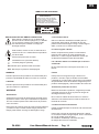
SAFETY RELATED SYMBOLS
WARNING:
TO REDUCE THE RISK OF FIRE OR
ELECTRIC SHOCK, DO NOT EXPOSE
TO RAIN OR HUMIDITY.DO NOT
REMOVE COVER. THIS PRODUCT IS
NOT INTENDED FOR USE OTHER THAN
STATED.
GRAPHICAL SYMBOLS EXPLANATION
This symbol, wherever used,alerts you to
the presence of un-isulated and dangerous
voltages within the product enclosure.
These are voltages that may be sufficient to
constitute the risk of electric shock.
External Connection
Always use proper ready-made insulated mains
cabling (power cord). Failure to do so could result
in shock or fire. If in doubt, seek advice from a
registered electrician.
Do not Remove Any Cover
This symbol, wherever used, alerts you to
important operating and maintenance
instructions. Please read.
Protective Ground Terminal
AC mains (Alternating Current)
Hazardous Live Terminal
ON: Denotes the product is turned on.
OFF: Denotes the product is turned off.
WARNING
Describes precautions that should be observed to
prevent the possibility of death or injury to the user.
CAUTION
Within the product are areas where high voltages
may bepresent. To reduce the risk of electric shock
do not remove any covers unless the AC mains
power cord is removed.
Covers should be removed by qualified service
personnel only.
No user serviciable parts inside.
Fuse
To prevent fire an damage to the product, use only
the recommended fuse type as indicated in this
manual. Do not short-circuit the fuse holder.
Before replacing fuse, make sure that the product
is OFF and disconnected from the AC outlet.
Protective Ground
Describes precautions that should be observed to
prevent damage to the product.
WARNING
Before turning the product ON, make sure that it is
connected to Ground. This is to prevent the risk of
electric shock.
Power Supply
Never cut internal or external Ground wires. Likewise,
never remove Ground wiring from the Protective
Ground Terminal.
Ensure that the mains source voltage (AC outlet)
matches the voltage rating of the product. Failure
to do so could result in damage to the product and
possibly the user.
Operating Conditions
Unplug the product before electrical storms occur
and when unused for long periods of time to reduce
the risk of electric shock or fire.
PA 6306
Always install in accordance with the manufacturer´s
instructions.
To avoid the risk of electrtic shock and damage, do
not subject the product to any liquid/rain or moisture.
Do not use this product when in close proximity to
water.
Do not install this product near any direct heat source.
Do not block areas of ventilation.
User Manual/Manual de uso
Pag. 1
EN
INSTALLATION NOTES
At all times, the amplifier has to be operated under appropriate conditions. This includes that the
operation location provideS sufficient ventilation and the device is not exposed to direct sunlight or direct
radiation or reflection from any heat source. Installing the loudspeaker systems choose a location
that is not affected by extreme and / or constant vibration or other mechanical oscillation. Also make
sure that the speakers are installed at locations that are free from dust and / or moisture.
CAUTION
Do not take the risk of electro-shock or shock hazard. To reduce the risk of electro-shock, all connections
have to be accomplished before it is permissible to connect the amplifier to the main supply, Before connecting
the appliance to the mains supply, once again make certain that all connections are carried out correctly and
that no short-circuits exist. The overall sound reinforcement installation has to be in accordance to the
laws, regulations, standards, and guidelines that are relevant and applicable in the country where the
equipment is going to be operated.
AC POWER SUPPLY CAUTION
Before using the amplifier for the first time, make sure that the appliance's voltage is in accordance to
your mains supply. Connect the amplifier only to grounded mains outlets. Connecting the amplifler to
the mains supply(115/230Vac) has to be accomplished by inserting the supplied mains cord into the
corresponding socket and afterward plugging it into a mains outlet.
PA 6306
User Manual/Manual de uso
Pag. 2
EN
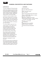
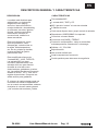
GENERAL DESCRIPTION AND FEATURES
DESCRIPTION
FEATURES
They are designed for PA system applications such as paging, announcements,
intercommunications, background music
and broad-casting in industrial plants,
offices, schools, churches, department
stores, shopping centres, night clubs,
dining rooms, convention halls,
auditoriums and recreation areas.
Three mic inputs
More kinds of protective for this series:
such as overload, short-circuits of output,
overheat; and you can use it safety and
freely.It's very simple to install, it also
can offer therack brackets according to
your repuirements.
The series amplifiers come with 3 microphone inputs, 1 AUX, TAPE and CD
input and Microphone inputs are
used with unbalanced microphone.
Auxiliary inputs are provided for high
level signal sources such as radio
tuner, tape recorder, mixer pre amplifier, remote microphone and record
player with ceramic or crystal type
cartridge. Speaker outputs are complete with 8 ohm, 70V and100V on the
terminal strip. An auxiliary output is
equipped for a booster amplifier and a
AUX output is equipped for a tape
Recorder.
1 AUX, TAPE and CD input.
MIC1 mute other inputs.
6 Zone output.
Each channel has the input level control.
Built-in USB/SD/MMC/ player in models.
Master volume control.
BASS and TREBLE tone control.
Multi-purpose protection---power-on-delay.
over heat, over voltage, over load.
Output---8Ω,70V,100V.
Low distortion.
High signal-noise rated(S/N).
Widely frequence response.
Perfect sound with PA speaker.
Each input volume can be controlled with
the corresponding individual input volume
control and can further be adjusted by
means of a master volume control and
individual bass and treble tone controls.
PA 6306
User Manual/Manual de uso
Pag. 3
EN
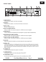
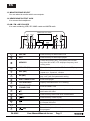
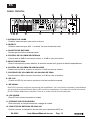
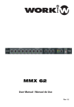
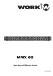
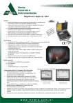
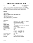
FRONT PANEL
4
1
2
3
5
5
6
7
15
14
13
8
12
11
9
10
1. CHIME SWITCH
Press down this switch, the chime is activated.
2. PRIORITY
Press down this switch, mic will mute the other music source.
3. INPUT JACK
Mic with unbalanced input.
4. INPUT VOLUME CONTROL
When it is 0dB. The volume is lowest; It is 10dB, the volume is highest.
5. ZONE SELECT
These 6 switches can distribute the input signal to 6 groups output independently.
6. HEADPHONE VOLUME CONTROL
When it is 0dB. The volume is lowest; It is 10dB, the volume is highest.
7. ZONE OUTPUT VOLUME CONTROL
When it is 0dB. The volume is lowest; It is 10dB, the volume is highest.
8. CLIP LED
When the clip led is iluminate, you should reduce the input signal level.l
9. SIGNAL LED
This LED will assist you in setting gain structure into the amp. With a source connected
to the amp and playing, turn up the channel gain control until this LED just starts to flash.
Once all the sources connected are playing, the SIGNAL LED may be on solid. This condition is normal.
10. POWER LED
This LED will illuminate when power is turned on.
11. POWER SWITCH
This switch is used to turn the main power ON and OFF.
12. PHONE INPUT JACK
It is allow the high level signal to input such as mobile phone or MP3.
PA 6306
User Manual/Manual de uso
Pag. 4
EN
13. MONITOR ZONE SELECT
You can select to monitor which zone outputs.
14. HEADPHONE OUTPUT JACK
It is connect the headphone.
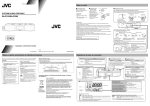
15. AM / FM + MP3 PLAYER
It is used containing USB, SD / MMC cards and AM FM radio
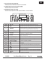
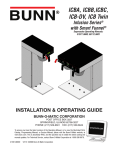
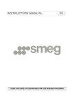
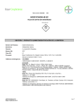
AM/FM+MP3 PLAYER
a
AM/FM
USB/SD(M1)
MP3
REP(M2)
MEMORY
EQ(M3)
b
c
d
f
(M4)
e
g
h
i
j
k
l
(M5)
o
n
m
a
AM / FM
Press this key to select AM or FM
b
MP3
Press this key to select Mp3 player.
c
MEMORY
Press the momory key, Then press the PRESET
key from M1 to M5, LCD displays frequency and
saving code,
d
USB / SD (M1)
Press this key to select the SD Card or USB player.
e
REP (M2)
f
EQ (M3)
g
USB CONNECTOR
Insert USB player
h
LCD DISPLAYS
Display the status when it is working
i
SD/MMC CARD
CONNECTOR
Insert SD/MMC card
Play the last program, in the radio model, It
attenuates the band
j
k
l
VOL(M4)
o
PA 6306
Press this key the sound level is attenuated.
Press this key it start to play
Play the next program, In the radio model,
It increase the band
m
n
Press this key to select repeat mode:
repeat one , repeat all , random
It can adjust panorama mode, such as classic ,
pop, rock, jazz, flat parameter setting
VOL+
(M5)
Press this key the sound level is increased.
Press this key it switches the power or stop
the program.
User Manual/Manual de uso
Pag. 5
EN
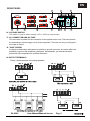
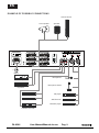
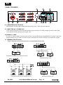
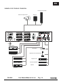
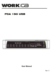
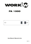
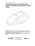
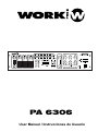
REAR PANEL
20
16
17
18
19
21
27
26 25
22
24
23
16. VOLTAGE SWITCH
This switch is used to select voltage (115V / 230V) as requirement.
17. AC CONNECTOR AND AC FUSE
This connector is meant for the connection of the spplied mains cord, The fuse protects
the alternating currents supply circuit of the equipment. The fuse can only be changed in
the event of a fault.
18. "GND" SCREW
In case the used mains outlet does not provide a ground conductor, this screw offers the
possibility to ground the amplifiers metal parts. Nevertheless, you should leave this
procedure to the experienced, qualified electrician.
19.OUTPUT TERMINALS
These 4 terminals allow connecting speakers.
+
-
-
PA 6306
User Manual/Manual de uso
Pag. 6
+
-
+
-
+
EN
20. FM ANTENNA
This antenna receive FM signals.
21. SOURCE SELECT SWITCH
Music source input select switch, this switch select the CD,AUX or TAPE.
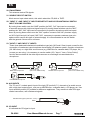
22. "INPUT 2" AND "INPUT 3" INPUTS SENSITIVITY AND XLR PHANTOM 24V SWITCH
INPUT VOLUME CONTROL
By turning these switch onto the "LINE" position the"IN2", "In3" input can be connected
to an audio source with high level signal output. By turning these switches onto the "MIC"
position the "IN2","IN3" input can be connected to a dynamic microphone with low impedance. By turning these switch onto the "24V" opsition connects "the 24V" phantom supply
on XLR of pin2 and pin3 of inputs "IN2","IN3", necessary to operate condenser type microphone which require this type of external supply. It is recommended to use this switch
with the general volume set on minimum.
23. "INPUT 2" AND "INPUT 3" INPUTS
These three balanced/unbalanced combination type jack (XLR and 6.3mm) inputs, meant for the
connection of condenser type microphone that accepts 24V phantom power, dynamic microphone
(30- 600 ohms) or a high level sound source (e.g. AM/FM tuner, cassette desk, CD player, etc.).
In case you are using, it is necessary to use the switch (22). "Input 1" has a "Voice Priority"
function that excludes all the other inputs as soon as a message is transmitted with a
microphone.
Balanced microphone
3-pin XLR plug
(seen from welded side)
Unbalanced microphone
3-pin XLR plug
(seen from welded side)
Unbalanced microphone
24. AUX INPUTS
The "R" and "L" sockets permit input of the right ("R")and left ("L") channels of an audio source
with a high-level output signal , such as an AM/FM tuner, a cassette deck, a CD player, etc. Use
input sensitivity switch (21),suitable for difference appliances. They are able to take RCA-type
coaxial connectors, and unbalanced signals.
Unbalanced signal (channel L or R)
Earth
RCA plug
25. CD INPUT
It is allowed the CD signal to input.
PA 6306
User Manual/Manual de uso
Pag. 7
EN
26. TAPE INPUT
It is allowed the tape recorder.
27. AM ANTENNA
This antenna recives AM signals.
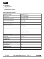
TECHNICAL SPECIFICATION
OUTPUT POWER CAPACITY
RMS: 30W * 6 ( 8Ω)
POWER SUPPLY
AC: 110-120V 50/60Hz
AC: 220-240V 50/60Hz
FREQUENCY RESPONSE
50Hz~18KHz (±3dB)
INPUT SENSITIVITY
MIC : -50dB
AUX : -16dB
TOTAL HARMONIC DISTORTION
<0.5%
SIGNNAL/NOISE RATIO
MIC≥65dB
AUX ≥75dB
CONTROLS
MIC LEVEL CONTROL
AUX LEVEL CONTROL
MASTER CONTROL
AC SWITCH
ZONE LEVEL CONTEOL
OUTPUT IMPEDANCE
8Ω
LINE OUTPUT
70V, 100V
CHIME FUNCTION
YES
VU-METER (LED)
YES
TELPHONE PAGING SELECT FUNCTION
NO
INPUT 1 PRIORITY
YES
ECHO FUNCTION
NO
MP3 PLAYER
YES
DIMENSION
420X280X88.8mm
PA 6306
User Manual/Manual de uso
Pag. 8
EN
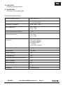
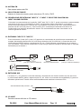
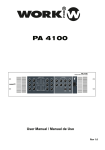
EXAMPLE OF POSSIBLE CONNECTIONS
Sound column
Horn speaker
230V
ZONE 1
8
ZONE 4
8
ZONE 2
8
ZONE 5
8
Speaker
115V
AC SELECT
AUX
TAPE
FM
~AC IN
CD
TAPE
PH.
48V
PH.
48V
INPUT3
INPUT2
CD
AM
ZONE 3
8
ZONE 6
8
110-120V~50/60Hz:T5A 250V
MADE IN CHINA
220-240V~50/60Hz:T2,5A 250V
INPUT4
Mains
Microphone
Power amplifier
Microphone stand
Equalizer
CDplayer
AM/FMtuner
CD player
AM/FM tuner
Cassette player
Cassette recorder
PA 6306
User Manual/Manual de uso
Pag. 9
ES
EN
SIMBOLOS DE SEGURIDAD
WARNING:
TO REDUCE THE RISK OF FIRE OR
ELECTRIC SHOCK, DO NOT EXPOSE
TO RAIN OR HUMIDITY.DO NOT
REMOVE COVER. THIS PRODUCT IS
NOT INTENDED FOR USE OTHER THAN
STATED.
EXPLICACION DE LOS SIMBOLOS GRAFICOS
Este símbolo, cuando se use, le alerta de la
presencia de una tensión peligrosa y no aislada
con el producto cerrado. Este voltaje puede
ser suficiente para constituir un riesgo de
descarga eléctrica.
Este simbolo, cuando se usa, le alerta de una
instrucción de uso o mantenimiento importante.
Por favor léala.
Terminal de protección de masa.
Conexionado Externo
Utilice un cable de alimentación aislado para el c
onexionado del producto. El utilizar de otro tipo
puede ocasionar descargas o fuego. Si tiene alguna
duda, consulte con un electricista experto.
No retire ninguna cubierta
Dentro del producto hay áreas con alta tensión
presente. Para reducir el riesgo de descargas
eléctricas, no retire ninguna cubierta a menos que
el cable de alimentación esté desconectado.
Alimentación AC (Corriente Alterna)
Terminal peligroso (Tensión)
ON: Denota que el producto está encendido.
OFF: Denota que el producto está apagado.
Las cubiertas deben ser retiradas por un técnico
cualificado.
No hay elementos de control para el usuario en el
interior.
WARNING
Fusible
Describe precauciones que deben ser observadas para
prevenir la posibilidad de daños o muerte en el usuario.
Para prevenir el riesgo de fuego o daños en el
producto, use sólo el tipo de fusible recomendado
e indicado en el manual No cortocircuite los terminales
del portafusible. Entes de sustituirlo asegúrese que el
producto está apagado y desconectado de la toma AC.
CAUTION
Describe precauciones que deben ser observadas para
prevenir daños en el producto.
Terminal de protección de tierra
Bantes de encender el producto, asegúrese que está
conectado a tierra con el fin de prevenir riesgos de
descarga eléctrica o fuego.
WARNING
Alimentación
Asegúrese que la toma de alimentación principal (Toma
AC) tiene el mismo valor que la marcada en el producto.
En caso contrario podría sufrir daños tanto el producto
como el usuario.
Desconecte el producto antes de unas tormenta eléctrica
y cuando no vaya a usarlo durante largos periodos de
tiempo paras reducir el riesgo de descargas o fuego.
Nuca corte los cables de tierra internos o externos.
Asimismo nunca desconecte el cable de tierra de su
terminal de conexión.
Condiciones de Funcionamiento
Instale la unidad siempre de acuerdo a la instrucciones
del fabricante.
Para evitar el riesgo de descargas eléctricas o daños,
no someta la unidad a ningún liquido, lluvia o humedad.
No use la unidad cerca del agua.
No instale la unidad bajo una fuente de calor.
No bloque las tomas de ventilación.
PA 6306
User Manual/Manual de uso
Pag. 10
ES
NOTAS DE INSTALACION
El amplificador siempre debe funcionar bajo las condiciones apropiadas. Estas incluyen que el lugar de
colocación de la unidad disponga de suficiente ventilación para la unidad y que no se encuentre expuesto a
la luz directa del sol, radiación o reflexión de ninguna fuente de calor. Al instalar la unidad, elija una localización
que no se vea afectada por una extrema o constante vibración u otra oscilación mecánica. Además, asegúrese
que los altavoces se instalan en una localización libre de polvo o humedad.
PRECAUCION
Evite el riesgo de descargas eléctricas. para reducir el riesgo de descargas eléctricas, todas las conexiones
debe realizadas antes de conectar el amplificador a la red eléctrica. Antes de conectar el amplificador a la red,
comprobar que todas las conexiones se han realizado correctamente y que no existen cortocircuitos. La
instalación de refuerzo de sonido tiene que estar de acuerdo a las leyes, regulaciones, standards y directrices
que afecten al dispositivo en el país de instalación.
ALIMENTACION AC, PRECAUCIONES
Antes de hacer funcionar la unidad por vez primera, asegúrese que la tensión de entrada de la unidad está en
concordancia con la toma mural. Conecte el amplificador siempre a una toma con conexión de toma de tierra. Al
conectar el amplificador a la red (115/2330V ac), debe hacerlo insertando el cable de alimentación incluido en la
toma correspondiente.
PA 6306
User Manual/Manual de uso
Pag. 11
ES
DESCRIPCION GENERAL Y CARACTERISTICAS
DESCRIPCION
CARACTERISTICAS
La unidad está diseñada para
aplicaciones con sistema de
megafonía como paging,
anuncios, intercomunicación,
musica ambiental o broadcasting
en oficionas, escuelas, iglesias,
tiendas, centros comerciales,
restaurantes, salones de
convenciones, auditorios o
áreas recreativas.
Tres entradas MIC
Esta serie dispone de varias
tipos de protección: como
sobrecargas, cortocircuitos en
la salida, sobretemperatura,
etc. Es muy simple de instalar,
incorpora aletas de fijación
para formato rack.
1 entrada AUX, TAPE y CD.
MIC1 permite “mutear” el resto de entradas
6 Salidas de zona.
Cada canal dispone de su propio control de entrada.
Reproductor USB/SD/MMC/ incorporado.
Control de volumen Master
Control de tono BASS y TREBLE.
Protección multipropósito - delay en encendido
sobretemperatura, sobretensión, sobrecarga.
Salidas---8Ω,70V,100V.
Baja distorsión.
Alta relación señal/ruido
Amplia respuesta en frecuencia.
Este amplificador dispone de
3 entrada MIC, 1AUX, TAPE/CD.
Las entrada MIC son para
micrófono desbalanceado. Las
entradas AUX son para fuentes
de señal de nivel alto como
sintonizadores, grabadores, previos,
etc. Las salidas de altavoz incorporan
salidas de 8 ohm, 70V y 100V en un
regleta de terminales. Incorpora una
salida auxiliar para grabación.
Sonido perfecto para altavoces de megafonia
El volumen de cada entrada puede ser
controlado de manera independiente
con su mando correspondiente, ademas
de ajustar el volumen master general
y los controles de tono bass y treble.
PA 6306
User Manual/Manual de uso
Pag. 12
ES
PANEL FRONTAL
4
1
2
3
5
5
6
7
15
14
13
8
12
11
9
10
1. INTERRUPTOR CHIME
Presione este interruptor para activar la sirena.
2. PRIORITY
Presione este interrupotr, MIC 1 “muteará” las otras funetes de audio.
3. CONECTOR DE ENTRADA
Entrada para micrófono desbalanceado.
4. CONTROL DE VOLUMEN DE ENTRADA
Cuando está en 0dB el volumen es mínimo, a 10 dB es valor es máximo.
5. SELECTOR DE ZONA
Estos 6 interruptores pueden distribuir la señal de entrada en 6 grupos de salida independientes.
6. CONTROL DE VOLUMEN DE AURICULARES
Cuando está en 0dB el volumen es mínimo, a 10 dB es valor es máximo.
7. CONTROLES DE VOLUMEN DE LAS SALIDAS DE ZONA
Cuando está en 0dB el volumen es mínimo, a 10 dB es valor es máximo.
8. LED CLIP
Cuando el LED Clip se ilumina, reduzca el nivel de la señal de entrada.
9. LED SIGNAL
Este LED le permite configurar la ganancia del amplificador. Con una fuente conectada y ejecutándose,
gire el control de ganancia hasta que el LED comience a parpadear. Con todas las fuentes en marcha,
el LED SIGNAL debe estar encendido. Este es su modo normal de funcionamiento.
10. LED POWER
Este LED se ilumina al encender la unidad.
11. INTERRUPTOR DE ENCENDIDO
Este interruptor se usa para encender o apagar la unidad..
12. CONECTOR DE ENTRADA DE AUXILIAR
Permite conectar un dispositivo de nivel alto como reproductor MP3, etc. .
PA 6306
User Manual/Manual de uso
Pag. 13
ES
13. SELECTOR DE ZONA MONITOR
Puede seleccionar monitorizar cualquier zona de salida.
14. CONECTOR DE SALIDA DE AURICULARES
Permite conectar unos auriculares.
15. REPRODUCTOR AM / FM + MP3
Permite conectar dispositivos USB, tarjetas SD/MMC o emisoras AM/FM
AM/FM+MP3 PLAYER
a
AM/FM
USB/SD(M1)
MP3
REP(M2)
MEMORY
EQ(M3)
b
c
d
f
(M4)
e
g
h
i
j
k
l
(M5)
o
n
m
a
AM / FM
Presione esta tecla para seleccionar AM o FM
b
MP3
Presione esta tecla para selccionar el reproductor MP3.
c
MEMORY
Presione esta tecla, luego presione las teclas PRESET
de M1 a M5, la pantalla mostrará la frecuencia
d
USB / SD (M1)
e
REP (M2)
f
EQ (M3)
g
CONECTOR USB
Inserte un dispositivo USB
h
PANTALLA LCD
Display the status when it is working
i
CONECTOR
TARJETA SD/MMC
l
VOL(M4)
o
PA 6306
Inserte una tarjeta SD/MMC
Presione esta tecla para atenuar el nivel de sonido.
Presione esta tecla para iniciar la reproducción.
Ejecuta el siguiente programa. en modo radio,
incrementa la banda.
m
n
Presione esta tecla para seleccionar el modo repeat,
repeat one , repeat all , random
Puede ajustar un modo de ecualización como classic,
pop, rock, jazz, flat
Ejecuta el último programa. en modo radio, atenua
la banda.
j
k
Presione esta tecla para seleccionar tarjeta SD o USB.
VOL+
(M5)
Presione esta tecla, el nivel de sonido se incrementa.
Presione esta tecla para conmutar la alimentación
o detener el programa.
User Manual/Manual de uso
Pag. 14
ES
PANEL TRASERO
20
16
17
18
19
21
27
26 25
22
24
23
16. CONMUTADOR DE TENSION
Este selector se utiliza para seleccionar la tensión (115V / 230V) que se requiera.
17. CONECTOR AC Y FUSIBLE AC
Este conector permite el conexionado del cable de red incluido. El fusible protege la unidad y sólo debe
ser sustituido cuando falle por tor de igual valor.
18.TORNILLO "GND"
En caso de utilizar cable de red sin toma de tierra, este tornillo ofrece la posibilidad de conectar a tierra las
partes metálicas de la unidad. De todas formas, esto debe ser llevado a cabo por un electricista experto.
19. TERMINALES DE SALIDA
Estos 4 bloques de terminales permiten el conexionado de altavoces.
+
-
+
-
Conectando altavoces a la salida de 8 ohm.
Impedancia total 8 ohm
+
-
Conectando altavoces a la salida de 70V.
PA 6306
User Manual/Manual de uso
-
Impedancia total 8 ohm
Pag. 15
+
ES
20. ANTENA FM
Esta antena recibe señal FM.
21. SELECTOR DE FUENTE
Selector de fuente de entrada, puede seleccionar CD, AUX y TAPE.
22. SENSIBILIDAD DE ENTRADAS "INPUT 2" Y "INPUT 3" SELECTOR PHANTOM 24V
INPUT VOLUME CONTROL
Colocando los conmutadores en la posición "LINE" para "IN 2" e "IN 3", puede conectarse a estas entradas
una fuente de alto nivel. Colocándolos en "MIC", las entradas pueden conectarse a un micrófono
dinámico de baja impedancia. Poniendo los conmutadores en la posición de "24V", habrá alimentación
phantom de 24V entre los pines 2 y 3 del conector XLR, necesaria para alimentar micrófonos de
condensador que requieran alimentación externa. Es recomendable usar este conmutador con el
volumen general al mínimo.
23. ENTRADAS "INPUT 2" E "INPUT 3"
Estos conectores Combi (XLR y Jack 1/4") permiten el conexionado de micrófonos de condensador que
acepten alimentación phantom de 24V, micrófonos dinámicos (de 30 a 600 ohm) o fuente de alto nivel:
sintonizadores AM/FM, pletinas, reproductores CD, etc.). Debe utilizarse conjuntamente con el selector
(22). La entrada 1 tiene función de prioridad, la cual excluye todas las fuentes de entrada ante un mensaje
transmitido por la entrada 1.
Micrófono balanceado
Conector XLR 3
(visto por el lado de soldadura)
Micrófono desbalanceado
Conector XLR 3
(visto por el lado de soldadura)
Micrófono desbalanceado
24. ENTRADAS AUX
Las tomas "L" y “R” permiten la conexión derecha e izquierda de una fuente de audio de nivel alto como
un sintonizador AM/FM, pletina, reproductor de CD, etc. Utilice el conmutador de sensibilidad (21) para las
diferentes aplicaciones. Permite utilizar señal desbalanceada mediante conectores RCA.
Señal desbalanceada (canales L y R)
Masa
Conector RCA
25. CD INPUT
Permite conectar señal de un CD externo
PA 6306
User Manual/Manual de uso
Pag. 16
ES
26. TAPE INPUT
Toma de grabación.
27. ANTENA AM
Esta antena recibe señal AM
ESPECIFICACIONES TECNICAS
POTENCIA DE SALIDA
RMS: 30W * 6 ( 8Ω)
ALIMENTACION
AC: 110-120V 50/60Hz
AC: 220-240V 50/60Hz
RESPUESTA EN FRECUENCIA
50Hz~18KHz (±3dB)
SENSIBILIDAD DE ENTRADA
MIC : -50dB
AUX : -16dB
DISTORSION ARMONICA
<0.5%
RELACION SEÑAL/RUIDO
MIC≥65dB
AUX ≥75dB
CONTROLES
CONTROL NIVEL MIC
CONTROL NIVEL AUX
CONTROL MASTER
INTERRUPTOR DE RED
CONTROL NIVEL ZONA
IMPEDANCIA DE SALIDA
8Ω
SALIDA LINE
70V, 100V
FUNCION CHIME
SI
VUMETRO (LED)
SI
FUNCION SELECCION TELEPHONE
NO
PRIORIDAD ENTRADA 1
SI
FUNCION ECHO
NO
REPRODUCTOR MP3
SI
DIMENSIONES
420X280X88.8mm
PA 6306
User Manual/Manual de uso
Pag. 17
ES
EJEMPLO DE POSIBLE CONEXION
Columna de sonido
Altavoz exponencial
230V
ZONE 1
8
ZONE 4
8
ZONE 2
8
ZONE 5
8
Altavoz
115V
AC SELECT
AUX
TAPE
FM
~AC IN
CD
TAPE
PH.
48V
PH.
48V
INPUT3
INPUT2
CD
AM
ZONE 3
8
ZONE 6
8
110-120V~50/60Hz:T5A 250V
MADE IN CHINA
220-240V~50/60Hz:T2,5A 250V
INPUT4
Alimentación
Micrófono
Amplificador
Micrófono de sobremesa
Ecualizador
Reprod. CD
Reprod. CD
Sintoniz. AM/FM
Sintoniz. AM/FM
Pletina
Grabador
PA 6306
User Manual/Manual de uso
Pag. 18
This symbol on the product or on its packaging indicates that this product
shall not be treated as household waste. Instead it shall be handed over to
the applicable collection point for the recycling of electrical an electronic
equipment. By ensuring this product is disposed of correctly, you will help
prevent potential negative consequences for the environment and human
health, which could otherwise be caused by inappropriate waste handling
of this product. The recycling of materials will help to conserve natural
resources. For more detailed information about recycling of this product,
please contact your local city office, your household waste disposal service
or the shop where you purchased the product.
Manufactured by
EQUIPSON, S.A.
http://www.equipson.es