1
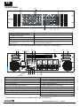
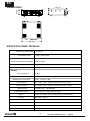
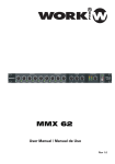
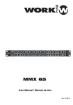
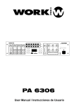
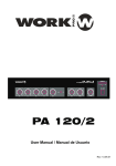
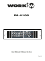
PA 4100
PA 4100
Multizone Mixer & Power Amplier
ON
OFF
ON
ON
OFF
OFF
User Manual / Manual de Uso
Rev 1.0
EN
SAFETY RELATED SYMBOLS
WARNING:
TO REDUCE THE RISK OF FIRE OR
ELECTRIC SHOCK, DO NOT EXPOSE
TO RAIN OR HUMIDITY. DO NOT
REMOVE COVER. THIS PRODUCT IS
NOT INTENDED FOR USE OTHER THAN
STATED.
GRAPHICAL SYMBOLS EXPLANATION
This symbol, wherever used,alerts you to
the presence of un-isulated and dangerous
voltages within the product enclosure.
These are voltages that may be sufficient to
constitute the risk of electric shock.
External Connection
Always use proper ready-made insulated mains
cabling (power cord). Failure to do so could result
in shock or fire. If in doubt, seek advice from a
registered electrician.
Do not Remove Any Cover
This symbol, wherever used, alerts you to
important operating and maintenance
instructions. Please read.
Within the product are areas where high voltages
may be present. To reduce the risk of electric shock
do not remove any covers unless the AC mains
power cord is removed.
Protective Ground Terminal
AC mains (Alternating Current)
Covers should be removed by qualified service
personnel only.
No user serviciable parts inside.
Hazardous Live Terminal
ON: Denotes the product is turned on.
Fuse
OFF: Denotes the product is turned off.
WARNING
Describes precautions that should be observed to
prevent the possibility of death or injury to the user.
CAUTION
To prevent fire an damage to the product, use only
the recommended fuse type as indicated in this
manual. Do not short-circuit the fuse holder.
Before replacing fuse, make sure that the product
is OFF and disconnected from the AC outlet.
Protective Ground
Describes precautions that should be observed to
prevent damage to the product.
Before turning the product ON, make sure that it is
connected to Ground. This is to prevent the risk of
electric shock.
WARNING
Power Supply
Never cut internal or external Ground wires. Likewise,
never remove Ground wiring from the Protective
Ground Terminal.
Ensure that the mains source voltage (AC outlet)
matches the voltage rating of the product. Failure
to do so could result in damage to the product and
possibly the user.
Operating Conditions
Unplug the product before electrical storms occur
and when unused for long periods of time to reduce
the risk of electric shock or fire.
1
Always install in accordance with the manufacturer´s
instructions.
To avoid the risk of electrtic shock and damage, do
not subject the product to any liquid/rain or moisture.
Do not use this product when in close proximity to
water.
Do not install this product near any direct heat source.
Do not block areas of ventilation.
User Manual/Manual de Uso
PA 4100
EN
FRONT PANEL
1 23
8
4 56 7
PA 4100
Multizone Mixer & Power Amplier
ON
OFF
9
ON
ON
OFF
OFF
10
11
12
7. Ready LED
8. Power ON LED
1. Master Output Volume Control
2. Treble Tone Control
3. Bass Tone Control
9. Input Volume Controls (1-4, AUX 1-2, CHIME, SIREN)
10. CHIME (Switch ON/OFF)
11. SIREN (Switch ON/OFF)
12. Power Switch ON/OFF
4. Protection LED
5. Clip LED
6. Signal LED
* NOTE: Items 1 to 7 are shown for OUTPUT channel 1. Outputs 2 - 4 are identical.
13 14
15 16 17 18
19
21
20
22
23
PA 4100
Multizone Mixer & Power Amplier
31
(bottom side)
30 29 28
26 25 24
27
13. OUTPUT 3 (high/low impedance speaker outputs) 22. OUTPUT 2 (high/low impedance speaker outputs)
14. OUTPUT 4 (high/low impedance speaker outputs) 23. OUTPUT 1 (high/low impedance speaker outputs)
15. Mains input socket
24. Input 4 (COMBI(XLR3P-Jack)/balanced)
25. Input 4 (Terminal block)
16. AC fuse holder
17. Power amp Input (RCA phono)
26. Input 4 (Dip-switch for functions)
18. Pre output (RCA phono)
27. TEL/EMER input level control
19. AUX 2 input (RCA phono)
28. TEL/EMER input terminals
20. AUX 1 input (RCA phono)
29. SIREN terminals
21. Input 1 Priority Terminals
30. CHIME priority terminals
31. Input Voltage Selector
* NOTE: Items 24 to 26 are shown for INPUT 4. INPUTS 1 - 3 are identical.
2
User Manual/Manual de Uso
PA 4100
EN
CONNECTIONS
Mains Connection (15)
The supply transformer has been designed for use on either 115V AC or 230 V AC, selected by a slide
switch on the bottom of the device. The amplifier is factory set at 230 V AC mains voltage.
Input Connection
Inputs 1-4 feature both balanced standard COMBI socket (1/4” stereo jack, and XLR 3P) and terminal blocks
on the rear panel.
Wiring is as follows:
(Front view)
PUSH
1
2
3
SLEEVE RING TIP
XLR 3P
1/4” STEREO JACK
Pin1 : Screen
Pin2 : Signal (live)
Pin3 : Signal (return)
Tip : Signal (live)
Ring : Signal (Return)
Sleeve : Screen
+
- GND
TERMINAL BLOCK
Pin+ : Signal (live)
Pin- : Signal (return)
GND : Screen
Turn the front panel potentiometers (9) clockwise to increase the volume or anticlockwise to reduce the volume.
Selected Functions by Dip-Switch block
NOTE: To ensure a correct
understanding. the
white coloured square
is considered the switch
in all pictures in this
user manual
Each input incorporates several functions
configurable through a dip-switch block:
ON
1
OFF
Switch 1: AUDIO SOUCE SELECTION: Setting the switch to the ON position, the input will accept
microphone level audio. Setting it to the OFF position, the input will accept LINE level.
Switch 2: PHASE INVERSION: Setting the switch to the ON position, the signal will be inverted 180º.
Setting it to the OFF position, the signal will be unaffected.
Switch 3: HIGH PASS FILTER: Setting the switch to the ON position, the input will be processed by a
high pass filter with a 200Hz cutoff frequency. Setting it to the OFF position, the
signal will be unaffected.
Switch 4: PHANTOM POWER: Setting the switch to the ON position, + 48V phantom power will be applied
for condenser microphones. Setting it to the OFF position, this function will be disabled.
The PA 4100 provides two auxiliary inputs (AUX 1-2) which may be used for connecting other signal sources
such as a Radio Tuner, MP3 player, computer, CD or Cassette player (LINE level). Connect the audio source to
the rear connectors (19, 20).Turn their respective potentiometers clockwise to increase the volume or
anticlockwise to reduce the volume.
These input sockets are standard RCA phonos, two sockets are supplied and these are linked together
internally in parallel, this allows stereo signal source to be used without the need to obtain a special lead,
however you may wish to check with the manufacturer of the signal source to ensure that no damage will result if
the left and right output channels are connected together in parallel.
Sleeve - Screen
Pin - Signal
RCA Phono plug connections
SLEEVE
3
PIN
User Manual/Manual de Uso
PA 4100
EN
PRIORITY
INPUT 1 has the highest priority (apart fromTEL/EMER), overriding the rest of inputs. To activate the priority state
short-circuit the Priority terminals (21) on the rear panel.
CHIME ON/OFF
To activate the CHIME, both the front panel switch (10) must be depressed, and a short-circuit made between the
CHIME PRIORITY terminals on the rear panel(30). This will activate the chime function (‘Ding Dong’
pre-annoucement chime). Whilst the CHIME state is enabled all inputs will be overridden.
The volume of the CHIME can be set from the CHIME potentiometer on the front panel.
on
off
SIREN ON/OFF
SIREN can be activated in one of two ways:
- Pressing the front panel switch (11)
In that case, the SIREN WILL BE ACTIVATED UNTIL THE SWITCH IS PRESSED AGAIN (OUT POSITION).
- Making a short-circuit in the SIREN terminals (29) in the rear panel.
In that case, the SIREN WILL BE ACTIVATED UNTIL THE SHORT-CIRCUIT IS REMOVED.
Whilst the SIREN state is enabled all inputs will be overridden.
The volume of the SIREN can be set from the SIREN potentiometer on the front panel.
on
off
Telephone/Emergency (28)
The Telephone/Emergency input is for emergency announcements/signals and is not affected by the Master
volume control. The volume can be set by the tel. paging volume control (27).
The terminals allows connection of a telephone/paging system interface.
NOTE: The Telephone/Emergency input has the highest priority, all other units will be overriden.
+
GND
4
-
User Manual/Manual de Uso
PA 4100
EN
Power In & Pre Out (17-18)
These sockets connect the mixer/preamplifier stage to the power amplifier stage. The connecting link must be
plugged in for normal operation as a mixer/amplifier. If a compressor/limiter, equalizer, or other external signal
processor is used in the sound system, connect the “PRE OUT” to the input of the external processor
and the output of the processor to “POWER IN” In the signal chain, “PRE OUT” is after the tone controls
and the master volume control.
Loudspeaker Connections
The PA 4100 includes 4 discrete outputs and each output section provides two different types of loudspeaker
outputs in each one: High impedance lines (25/70/100V) and low impedance (4, 8Ω). You can only use one of
these outputs at any one time; any attempt to use two or more of these may result in damage to the amplifier.
+
0
100V
0
100V
0
100V
4 ohm
Connecting a single speaker to the 4 ohm output
Connecting multiple speakers in parallel to the 100V output
+
-
0
70V
0
70V
0
+
-
70V
4 ohm
4 ohm
Connecting two speakers in series to the 8 ohm output.
Connecting multiple speakers in parallel to the 70V output
5
User Manual/Manual de Uso
PA 4100
EN
DIMENSIONS
88 mm
410 mm
483 mm
TECHNICAL SPECIFICATIONS
Output Power (RMS)
Audio Inputs
4 x 250 W
4 MIC / LINE, 2 AUX level
INPUTS
MIC (Impedance/Sensitivity)
600 Ω / 2.8mV
LINE (Impedance/Sensitivity)
3k Ω / 316 mV
AUX (Impedance/Sensitivity)
50k Ω / 316 mV
OUTPUTS
Low Impedance
High Impedance Line
Frequency Response
EQ Control (Bass)
EQ Control (Treble)
S/N ratio
Total harmonic distortion
4/8Ω
25 / 70 / 100 V
50 Hz ‐ 17 kHz +/‐ 3dB
+/- 10 dB / 22 Hz ‐ 180 Hz /Centre Frequency 50 Hz
+/- 10 dB / 3k Hz ‐ 20 kHz /Centre Frequency 12 kHz
> 90 dB (Line), > 80 dB (MIC)
Less than 1% at 1 kHz, rated power
Chime
Two tone chime (‘Ding‐dong’ pre-announcement chime)
Priority
Tel./Emer. ‐ MIC 1
Main Supply AC power
Consumption
Dimensions
Weight
115 /230 V - 50/60 Hz
1800 W
483 x 132 x 410 mm ( W x H x D)
25.2 kg.
6
User Manual/Manual de Uso
PA 4100
ES
EN
SIMBOLOS DE SEGURIDAD
WARNING:
TO REDUCE THE RISK OF FIRE OR
ELECTRIC SHOCK, DO NOT EXPOSE
TO RAIN OR HUMIDITY. DO NOT
REMOVE COVER. THIS PRODUCT IS
NOT INTENDED FOR USE OTHER THAN
STATED.
EXPLICACION DE LOS SIMBOLOS GRAFICOS
Este símbolo, cuando se use, le alerta de la
presencia de una tensión peligrosa y no aislada
con el producto cerrado. Este voltaje puede
ser suficiente para constituir un riesgo de
descarga eléctrica.
Este simbolo, cuando se usa, le alerta de una
instrucción de uso o mantenimiento importante.
Por favor léala.
Terminal de protección de masa.
Conexionado Externo
Utilice un cable de alimentación aislado para el c
onexionado del producto. El utilizar de otro tipo
puede ocasionar descargas o fuego. Si tiene alguna
duda, consulte con un electricista experto.
No retire ninguna cubierta
Dentro del producto hay áreas con alta tensión
presente. Para reducir el riesgo de descargas
eléctricas, no retire ninguna cubierta a menos que
el cable de alimentación esté desconectado.
Alimentación AC (Corriente Alterna)
Las cubiertas deben ser retiradas por un técnico
cualificado.
Terminal peligroso (Tensión)
ON: Denota que el producto está encendido.
No hay elementos de control para el usuario en el
interior.
OFF: Denota que el producto está apagado.
WARNING
Fusible
Describe precauciones que deben ser observadas para
prevenir la posibilidad de daños o muerte en el usuario.
Para prevenir el riesgo de fuego o daños en el
producto, use sólo el tipo de fusible recomendado
e indicado en el manual No cortocircuite los terminales
del portafusible. Entes de sustituirlo asegúrese que el
producto está apagado y desconectado de la toma AC.
CAUTION
Describe precauciones que deben ser observadas para
prevenir daños en el producto.
Terminal de protección de tierra
Bantes de encender el producto, asegúrese que está
conectado a tierra con el fin de prevenir riesgos de
descarga eléctrica o fuego.
WARNING
Alimentación
Asegúrese que la toma de alimentación principal (Toma
AC) tiene el mismo valor que la marcada en el producto.
En caso contrario podría sufrir daños tanto el producto
como el usuario.
Desconecte el producto antes de unas tormenta eléctrica
y cuando no vaya a usarlo durante largos periodos de
tiempo paras reducir el riesgo de descargas o fuego.
Nuca corte los cables de tierra internos o externos.
Asimismo nunca desconecte el cable de tierra de su
terminal de conexión.
Condiciones de Funcionamiento
Instale la unidad siempre de acuerdo a la instrucciones
del fabricante.
Para evitar el riesgo de descargas eléctricas o daños,
no someta la unidad a ningún liquido, lluvia o humedad.
No use la unidad cerca del agua.
No instale la unidad bajo una fuente de calor.
No bloque las tomas de ventilación.
7
User Manual/Manual de Uso
PA 4100
ES
PANEL FRONTAL
1 23
8
4 56 7
PA 4100
Multizone Mixer & Power Amplier
ON
OFF
9
1. Control de volumen salida Masterl
2. Treble (Control de tono)
3. Bass (Control de Tono)
4. LED Protection
5. LED Clip
6. LED Signal
ON
ON
OFF
OFF
10
11
12
7. LED Ready
8. LED Power ON
9. Controles de volumen de entrada (1-4, AUX 1-2, CHIME, SIREN)
10. CHIME (Interruptor ON/OFF)
11. SIREN (Interruptor ON/OFF)
12. Interruptor principal ON/OFF
* NOTA: Los puntos del 1 al 7 están mostrados para OUTPUT channel 1. Outputs 2 - 4 son idénticas.
13 14
15 16 17 18
19
22
21
20
23
PA 4100
Multizone Mixer & Power Amplier
31
(bottom side)
30 29 28
26 25 24
27
13. OUTPUT 3 (Salida altavoces alta/baja impedancia) 22. OUTPUT 2 (Salida altavoces alta/baja impedancia)
14. OUTPUT 4 (salida altavoces alta/baja impedancia) 23. OUTPUT 1 (Salida altavoces alta/baja impedancia)
15. Toma de alimentación
24. Entrada 4 (COMBI(XLR3P-Jack)/balanceada)
25. Entrada 4 (Terminal block)
16. Portafusible AC
17. Entrada Power amp (RCA)
26. Entrada 4 (Dip-switch para funciones)
18. Salida Pre out (RCA)
27. Control de nivel de entrada TEL/EMER
19. Entrada AUX 2 (RCA )
28. Terminales de entrada TEL/EMER
20. Entrada AUX 1 (RCA)
29. Terminales SIREN
21. Terminales de Prioridad Input 1
30. Terminales de prioridad CHIME
31. Selector de tensión de entrada
* NOTA: Los puntos 24 a 26 están mostrados para INPUT 4. INPUTS 1 - 3 son idénticasl.
8
User Manual/Manual de Uso
PA 4100
ES
EN
CONEXIONES
Conexión de alimentación (15)
El transformador de alimentación ha sido diseñado para su uso tanto a 115V AC como 230 V AC,
seleccionado por un interruptor deslizante situado en la parte inferior de la unidad. El amplificador viene
configurado de fábrica a 230 V AC.
Conexiones de Entrada
Las entradas 1-4 incorporan conector COMBI standard balanceado (jack 1/4” estéreo, y XLR 3P) y
terminal blocks en el panel trasero.
El cableado es el siguiente:
(Vista frontal)
PUSH
1
2
3
CASQUILLO ARO TIP
XLR 3P
JACK STEREO 1/4”
Pin1 : Malla
Pin2 : Señal (vivo)
Pin3 : Señal (retorno)
Tip : Señal (vivo)
Aro : Señal (Retorno)
Casquillo : Malla
+
- GND
TERMINAL BLOCK
Pin+ : Señal (vivo)
Pin- : Señal (Retorno)
GND : Malla
Gire los potenciómetros frontales (9) en sentido horario para incrementar el volumen, y antihorario para reducirlo.
Funciones seleccionadas con el bloque Dip-Switch
NOTA: Para asegurar una mejor
comprensión, el recuadro
coloreado en blanco es
considerado el interruptor en
todos los dibujos de este manual.
Cada entrada incorpora varias funciones
configurables mediente el bloque dip-switch:
ON
1
OFF
Switch 1: SELECCION DE FUENTE DE AUDIO: Configurando el switch en la posición ON, la entrada
aceptará nivel de micrófono. En la posición OFF aceptará señal LINE.
Switch 2: INVERSION DE FASE: Configurando el switch en la posición ON, la señal se invertirá 180º.
Configurando en la posición OFF, la señal no se verá afectada.
Switch 3: FILTRO PASO ALTO: Configurando el switch en la posición ON, la entrada será procesada por un
filtro paso alto con una frecuencia de corte de 200Hz.
Configurando en la posición OFF, la señal no se verá afectada.
Switch 4: ALIMENTACION PHANTOM : Configurando el switch en la posición ON, se aplicarán + 48V de
alimentación phantom para micrófonos de condensador.
Configurando el switch a la posición OFF, la función se deshabilita.
PA 4100 incorpora dos entradas auxiliares (AUX 1-2) las cuales pueden ser usadas para conectar otras
fuentes de señal como sintonizadores de radio, reproductores Mp3, ordenadores o reproductores CD o
cassette (nivel LINE). Conecte la fuente de audio a los conectores traseros (19, 20). Gire su respectivo
potenciómetro en sentido horario para incrementar el volumen o antihorario para reducirlo.
Estos conectores de entrada son tomas RCA standard, existen 2 tomas y están conectadas internamente
en paralelo, esto permite el uso de fuente de audio estéreo sin la necesidad de obtener un cableado
especial, de todas formas es aconsejable consultar con el fabricante del dispositivo a conectar con el fin
de no dañar la unidad en el caso de que los canales de salida derecha/izquierda se conecten juntos en
paralelo.
Casquillo - Malla
Pin - Señal
Conexionado de un conector RCA
CASQUILLO
9
PIN
User Manual/Manual de Uso
PA 4100
ES
PRIORIDAD
INPUT 1 tiene la mayor prioridad (aparte de TEL/EMER), anulando el resto de entradas. Para activar el
estado de prioridad cortocircuite los terminales Priority (21) en el panel trasero.
CHIME ON/OFF
Para activar el CHIME, el switch del panel frontal (10) debe estar activado, y debe realizarse un cortocircuito
en los terminales CHIME PRIORITY del panel trasero l(30). esto activará la función chime (Chime ‘Ding Dong’
de pre-anuncio). Mientras el estado CHIME esté habilitado todas las entradas estarán anuladas.
El volumen de CHIME puede ser configurado desde el potenciómetro CHIME situado en el panel trasero.
on
off
SIREN ON/OFF
SIREN puede ser activada de una de estas 2 formas:
- Presionando en interruptor del panel frontal (11)
En este caso LA SIRENA ESTARA ACTIVA HASTA QUE EL INTERRUPTOR VUELVA A SER
PRESIONADO (Posición OFF).
- Haciendo un cortocircuito en los terminales SIREN (29) del panel trasero.
En este caso, LA SIRENA ESTARA ACTIVADA HASTA QUE SE LIMINE EL CORTOCIRCUITO.
Mientras esté activada SIREN, todas las entradas estará anuladas.
El volumen SIREN puede ser configurado mediente el potenciómetro SIREN del panel frontal.
on
off
Telephone/Emergency (28)
La entrada Telephone/Emergency es para señales/anuncio0s de emergencia y no se ve afectada con el
control de volumen Master. El volumen puede ser configurado por el control de volumen (27).
Los terminales permiten la conexión de un interfaz telephone/paging.
NOTA: La entrada Telephone/Emergency input tiene la máxima prioridad, el resto de entradas se
anularán.
+
GND
10
-
User Manual/Manual de Uso
PA 4100
ES
EN
Power In y Pre Out (17-18)
Estos conectores permiten el conexionado de un sistema mezclador/preamplificador al sistema de
amplificado. El conexionado debe realizarse como un sistema de mezclador típico. Si se dispone de
un compresor/limitador, ecualizador u otro tipo de procesador de audio en el sistema de sonido,
conecte la toma “PRE OUT” a la entrada del procesador externo y la salida del procesador a la toma
“POWER IN”. En la cadena de unidades, “PRE OUT” está después del control de tono y el control
master de volumen.
Conexionado de los Altavoces
PA 4100 incluye 4 salidas discreats y cada sección incorpora 2 diferentes tipos de salida de altavoz:
Líneas de alta impedancia (25/70/100V) y baja impedancia (4, 8Ω). Sólo puede utilizar una de estas salidas
a la vez, cualquier intento de usar 2 o más puede ocasionar daños en el amplificador.
+
0
100V
0
100V
0
100V
4 ohm
Conectando un sólo altavoz a la salida de 4 ohm
Conectando múltiples altavoces en paralelo en la salida de 100V
+
-
0
70V
0
70V
0
+
-
70V
4 ohm
4 ohm
Conectando dos altavoces en serie en la salida de 8 ohm.
Conectando múltiples altavoces en paralelo en la salida de 70V
11
User Manual/Manual de Uso
PA 4100
ES
EN
DIMENSIONES
88 mm
410 mm
483 mm
ESPECIFICACIONES TECNICAS
Potencia de Salida (RMS)
Entradas de Audio
4 x 250 W
4 MIC / LINE, 2 AUX
ENTRADAS
MIC (Impedancia/Sensibilidad)
600 Ω / 2.8mV
LINE (Impedancia/Sensibilidad)
3k Ω / 316 mV
AUX (Impedancia/Sensibilidad)
50k Ω / 316 mV
SALIDAS
Baja Impedancia
Línea de Alta impedancia
Respuesta de Frecuencia
4/8Ω
25 / 70 / 100 V
50 Hz ‐ 17 kHz +/‐ 3dB
Control (Bass)
+/- 10 dB / 22 Hz ‐ 180 Hz /Frecuencia central 50 Hz
Control (Treble)
+/- 10 dB / 3k Hz ‐ 20 kHz /Frecuencia central 12 kHz
Relación S/N
Distorsión Armónica
> 90 dB (Line), > 80 dB (MIC)
Menos del 1% a 1 kHz, potencia típica
Chime
Chime de 2 tonos ( Chime ‘Ding‐dong’ de pre-anuncio)
Priority
Tel./Emer. ‐ MIC 1
Alimentación AC
Consumo
Dimensiones
Peso
115 /230 V - 50/60 Hz
1800 W
483 x 132 x 410 mm ( W x H x D)
25.2 kg.
12
User Manual/Manual de Uso
PA 4100
This symbol on the product or on its packaging indicates that this product
shall not be treated as household waste. Instead it shall be handed over to
the applicable collection point for the recycling of electrical an electronic
equipment. By ensuring this product is disposed of correctly, you will help
prevent potential negative consequences for the environment and human
health, which could otherwise be caused by inappropriate waste handling
of this product. The recycling of materials will help to conserve natural
resources. For more detailed information about recycling of this product,
please contact your local city office, your household waste disposal service
or the shop where you purchased the product.
Manufactured by
EQUIPSON, S.A.
http://www.equipson.es