1
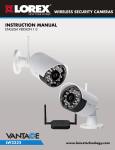
10X PAN-TILT-ZOOM CAMERA Instruction Manual English Version 4.0 RETAIL INDUSTRY www.lorextechnology.com Copyright © 2013 Lorex Technology Inc. BUSINESS HOME OUTDOOR LZC7091 Thank you for purchasing the LOREX Super+ Resolution 10X PTZ Speed-Dome Camera. This manual refers to the following models: • LZC7091 For the latest online manual and to learn about our complete range of accessory products, please visit our website at: www.lorextechnology.com CAUTION RISK OF ELECTRIC SHOCK DO NOT OPEN DURING OPERATION CAUTION: NO USER SERVICABLE PARTS INSIDE. REFER SERVICING TO QUALIFIED SERVICE PERSONNEL. The lightning flash with arrowhead symbol, within an equilateral triangle, is intended to alert the user to the presence of uninsulated "dangerous voltage" within the products ' enclosure that may be of sufficient magnitude to constitute a risk of electric shock. The exclamation point within an equilateral triangle is intended to alert the user to the presence of important operating and maintenance (servicing) instructions in the literature accompanying the appliance. CAUTION: TO PREVENT ELECTRIC SHOCK, MATCH WIDE BLADE OF THE PLUG TO THE WIDE SLOT AND FULLY INSERT. NEED HELP? CO NTACT US F I R S T DO NOT RETURN THIS PRODUCT TO THE STORE Please make sure to register your product at www.lorextechnology.com to receive product updates and technical support. 2 Easy Ways to Contact Us Online: Product Support is available 24/7 including product information, user manuals, quick start up guides and FAQ’s at www.lorextechnology.com/support For all other matters, visit www.lorextechnology.com By Phone: North America: Customer Service (for warranty matters): 1-888-425-6739 (1-888-42-LOREX) Tech Support (for technical/installation issues): 1-877-755-6739 (1-877-75-LOREX) Mexico: 001-800-681-9263, 001-800-514-6739 International: +800-425-6739-0 (Example: From the UK, dial 00 instead of +) FEB 12 2013 - R15 VIEW YOUR WORLD™ VOIR VOTRE MONDEMD VEA SU MUNDO™ ¿NECESITA AYUDA? BESOIN D’ASSISTANCE? COMUNÍQUESE PRIMERO CON NOSOTROS COMMUNIQUEZ D’ABORD AVEC NOUS NO DEVUELVA ESTE PRODUCTO A LA TIENDA NE RETOURNEZ PAS CE PRODUIT AU MAGASIN Por favor, registre su producto en www.lorextechnology. com para recibir actualizaciones del producto y asistencia técnica. Veuillez enregistrer votre produit sur le site www.lorextechnology.com afin de recevoir des mises à jour et le soutien technique pour votre produit. Hay 2 maneras fáciles de comunicarse con nosotros: 2 façons simples de communiquer avec nous : En línea: En ligne : Apoyo al cliente está disponible 24/7, incluyendo información del producto, manuales para el usuario, guías de inicio rápido y preguntas más frecuentes en: À votre disposition 24/7, le soutien pour les produits comprend les renseignements sur les produits, guides d’utilisation, guides de départ rapide et FAQ : Para todo lo demás, visite www.lorextechnology.com Pour toutes les autres questions, visitez www.lorextechnology.com Por teléfono: Par téléphone : Norte América: En Amérique du Nord : www.lorextechnology.com/support Atención al cliente (para asuntos de la garantía - garantía válida sólo en E.U.A., vea la garantía ofrecida por el importador): 1-888-425-6739 (1-888-42-LOREX) Asistencia técnica (para asuntos técnicos o de instalación): 1-877-755-6739 (1-877-75-LOREX) www.lorextechnology.com/support Service à la clientèle (pour tout ce qui concerne la garantie) : 1-888-425-6739 (1-888-42-LOREX) Soutien technique (pour les questions d’ordre technique ou relatives à l’installation) : 1-877-755-6739 (1-877-75-LOREX) Mexique : 001-800-681-9263, 001-800-514-6739 Teléfono y Servicios Válidos Sólo en E.U.A.: 001-800-681-9263, 001-800-514-6739 International : +800-425-6739-0 (par exemple : à partir du Royaume-Uni, composez le 00 au lieu de +) Internacional: +800-425-6739-0 FEB 12 2013 - R15 B E F O R E Y O U S TA R T Please make sure to register your product at www.lorextechnology.com to receive product updates and technical support THIS PRODUCT MAY REQUIRE PROFESSIONAL INSTALLATION LOREX IS COMMITTED TO FULFILLING YOUR SECURITY NEEDS • We have developed user friendly products and documentation. Please read the Quick Start Guide and User Manual before you install this product. • Consumer Guides and Video Tutorials are available on our web site at www.lorextechnology.com/support • If you require further installation assistance, please visit www.lorextechnology.com/installation or contact a professional installer. • Please note that once the components of this product have been unsealed, you cannot return this product directly to the store without the original packaging. FEB 12 2013 - R9 AVANT DE COMMENCER ANTES DE EMPEZAR Veuillez enregistrer votre produit sur le site www.lorextechnology.com afin de recevoir des mises à jour et le soutien technique pour votre produit. Cerciórese de por favor colocar su producto en www.lorextechnology.com para recibir actualizaciones y la información del producto y soporte técnico. CE PRODUIT PEUT NÉCESSITER UNE INSTALLATION PROFESSIONNELLE ESTE PRODUCTO PUEDE EXIGIR UNA INSTALACIÓN PROFESIONAL LOREX S’ENGAGE À RÉPONDRE À VOS BESOINS EN MATIÈRE DE SÉCURITÉ LOREX SE COMPROMETE A SATISFACER SUS NECESIDADES EN SEGURIDAD • Nous avons conçu et développé une documentation et des produits extrêmement conviviaux. Veuillez lire le Guide de départ rapide et le Guide d’utilisation avant d’installer ce produit. • Favor de leer la guía de instalación rápida y la guía del usuario antes de instalar este producto. • Des guides pour consommateurs et des tutoriels vidéo vous sont offerts sur notre site Web : www.lorextechnology.com/support • Si vous avez besoin de plus d’assistance pour l’installation de ce produit, veuillez visiter le site www.lorextechnology/installation ou communiquez avec un installateur professionnel. • Veuillez prendre note que lorsque vous avez déballé les pièces et composantes de ce produit, vous ne pouvez pas retourner celui-ci directement au magasin sans son emballage original. • Puede conseguir las guías del consumidor y los cursos en enseñanza video sobre el Internet visitando www.lorextechnology.com/support • Si necesita ayuda para la instalación, visite www.lorextechnology.com/installation o contacte un especialista en instalaciones. • Favor de notar que una vez que los componentes de este producto han sido removidos del embalaje, no podrá devolver este producto directamente a la tienda. www.lorextechnology.com VIEW YOUR WORLD™ VOIR VOTRE MONDEMD VEA SU MUNDO™ FEB 12 2013 - R9 Features English • Latest Sony EXview™ II image sensor for best-in-class low light performance1 • Sony Effio™ video image processor delivers up to 700TV lines of resolution • 10X Optical Zoom and 10X Digital Zoom to focus in on even the finest details • Complete area coverage with 360 degrees per second panning speed • Program preset viewing points when connected to a DVR • ClearNight technology with Digital Noise Reduction improves low light performance and recording efficiency by up to 30% • Accurate colors with Lorex’s automatic light filtering technology • Weatherproof (IP66) rated using included wall mount2 • Connects to any Lorex Eco™ or Edge™ series DVR for local or remote operation • Removable camera base for easier and safer installation • 100ft all-in-one extension cable included for installation location flexibility As our products are subject to continuous improvement, Lorex reserves the right to modify product design, specifications and prices, without notice and without incurring any obligation. E&OE 1 This camera features an ultra-low light sensitive image sensor and therefore does not feature Infra-Red LEDs. The camera requires ambient lighting (for example, street/building lighting, star or moon light) to render a night time image. In total darkness (zero Lux) the camera will not produce a night time image and therefore the camera should not be installed in completely dark areas. 2 Wall mount required for outdoor installation. Not intended for submersion in water. Installation in a sheltered location recommended. i Safety Instructions • Read this guide carefully and keep it for future reference. • Follow all instructions for safe use of the product and handle with care. • Use the camera within given temperature, humidity, and voltage levels noted in the Technical Specifications. • Camera is rated for outdoor use and is weatherproof using included wall mount only. For indoor installations, camera may be directly attached to a ceiling. • Camera is not intended for submersion in water. Installation under a sheltered environment is recommended. • Do not disassemble the camera. • Do not point the camera directly towards the sun or a source of intense light. • Use only the supplied regulated power supply. Use of a non-regulated, non-conforming power supply can damage this product and voids the warranty. • Make sure to install the camera in a location that can support the camera weight. • Make sure there are no live electrical cables in the area where you plan to mount the camera. • Periodic cleaning may be required. Use a damp cloth only. Do not use anything other than water to clean the dome cover, as chemicals such as acetone can permanently damage the plastic. ii TABLE OF CONTENTS English 1. Getting Started . . . . . . . . . . . . . . . . . . . . . . . . . . . . . . . . . 1 2. Connecting the Camera . . . . . . . . . . . . . . . . . . . . . . . . . . 2 2.1 Default Protocol Information . . . . . . . . . . . . . . . . . . . . . . . . . . . .6 3. Installation. . . . . . . . . . . . . . . . . . . . . . . . . . . . . . . . . . . . . 7 3.1 Installation Tips and Warnings . . . . . . . . . . . . . . . . . . . . . . . . . . .7 3.2 Extension Cables . . . . . . . . . . . . . . . . . . . . . . . . . . . . . . . . . . . . . .8 3.3 Wall Mount Installation (Indoor/Outdoor) . . . . . . . . . . . . . . . . . .9 3.4 Ceiling Install (Indoor Only) . . . . . . . . . . . . . . . . . . . . . . . . . . . . .12 4. Controlling the PTZ Camera with your DVR . . . . . . . . 16 4.1 Initial Setup . . . . . . . . . . . . . . . . . . . . . . . . . . . . . . . . . . . . . . . . . .16 4.2 Controlling the Camera . . . . . . . . . . . . . . . . . . . . . . . . . . . . . . . .17 4.3 PTZ Presets and PTZ Cruise . . . . . . . . . . . . . . . . . . . . . . . . . . . .19 4.4 Setting PTZ Presets on the ECO2 DVR . . . . . . . . . . . . . . . . . . . .19 4.5 Selecting PTZ Presets on the ECO2 DVR . . . . . . . . . . . . . . . . . .20 4.6 Deleting PTZ Presets on the ECO2 DVR . . . . . . . . . . . . . . . . . . .20 4.7 Starting / Stopping PTZ Cruise on the ECO2 DVR . . . . . . . . . . .20 5. Changing Protocol Information. . . . . . . . . . . . . . . . . . . 21 5.1 Accessing the DIP Switches . . . . . . . . . . . . . . . . . . . . . . . . . . . .22 5.2 Setting the Camera ID . . . . . . . . . . . . . . . . . . . . . . . . . . . . . . . . .22 5.3 Setting the Camera Protocol and Baud Rate . . . . . . . . . . . . . . .24 6. Technical Specifications. . . . . . . . . . . . . . . . . . . . . . . . . 25 7. Dimensions . . . . . . . . . . . . . . . . . . . . . . . . . . . . . . . . . . . 26 8. Troubleshooting . . . . . . . . . . . . . . . . . . . . . . . . . . . . . . . 27 iii iv Getting Started 1. GETTING STARTED English Before you start, ensure you have received all the items listed below: 3ft BNC/Power/RS485 Cable Camera 100ft BNC/Power/RS485 Extension Cable 13V DC Power Adapter Instruction Manual Mounting Screw Kit Wall Mount Kit Foam Pad 1 Connecting the Camera 2. CONNECTING THE CAMERA It is recommended to connect the camera to your DVR and test the PTZ controls before permanent installation. 3ft BNC / Power / RS485 cable 6-Pin Connector 1 Female BNC 2 3 4 Camera Male DC Power 100ft BNC / Power / RS485 extension cable Power adapter 5 Female DC Power RS485 Red: + Black: - 6 DVR RS485 Ports 7 Male BNC DVR Video Input 2 1. Connect the 6-pin connector on the 3ft cable to the camera. • To do this, you must remove the camera from the case. Rotate the dome cover counterclockwise to remove. Remove the base attachment screws (3x) and remove the camera base. See illustration below. Base attachment Dome screws cover Camera Camera base Removing the camera from the case NOTE: Do not use force when pulling out the 6-pin connector. The 6-pin connector has a release latch under the connector. Press the latch when disconnecting it from the camera. Release latch 2. Connect the female power connector on the 3ft cable to the male power connector on the 100ft extension cable. OR Connect the power adapter directly to the camera and to a local power outlet. 3 English Connecting the Camera Connecting the Camera 3. Use a Philips screwdriver (not included) to loosen the 2 screws on the RS485 connection block furthest from the pre-attached wires. Insert the RS485 wires into the RS485 connection block (red to red, black to black). Tighten the screws on the RS485 connection block to Loosen screws Insert wires secure the wires in place. 4. Connect the BNC female connector on the 3ft cable to the BNC male connector on the 100ft extension cable. 5. Connect the power connector on the 100ft extension cable to the included power adapter. Plug the power adapter into a power outlet. 6. Connect the RS485 connectors to the RS485 ports on the alarm block on your DVR. The layout of the alarm block may differ depending on your DVR model (common terms include RS485, RS422, or PTZ). • The RS485 connectors are a pair + / - RS485 Ports of bare 24-gauge wires. The red Insert a wire is positive (+) and is screwdriver and connected to the + port on the then insert wires RS485 section of the alarm Spring loaded lock alarm block block, and the black wire is negative (-) and is connected to the - port. • Most DVR’s either use screws or + / - RS485 Ports a spring loaded lock to hold the Tighten screws RS485 wires in place. For a above ports to spring loaded lock, insert a secure wires screwdriver or small object into the lock, insert the wires, and Screw lock alarm block then remove the screwdriver to lock the wires in place. 4 Connecting the Camera English • If the wires can be easily removed, they may become disconnected and affect control of the camera. Use wire strippers (not included) to expose more of the wires if needed. 7. Connect the male BNC connector on the 100ft extension cable to an available Video IN port on the DVR. 5 Connecting the Camera 2.1 DEFAULT PROTOCOL INFORMATION Unlike standard security cameras, PTZ (pan-tilt-zoom) cameras require special protocol information to enable a Security DVR to control the camera movement. Input the following information into your DVR to enable PTZ controls. • Default ID: 1 • Default Baud Rate: 2400 • Default Protocol: Pelco-D For details on setting up your DVR with the PTZ camera, see “Controlling the PTZ Camera with your DVR” on page 16. You will not need to change the default protocol information on your camera unless you are using multiple PTZ cameras or if your DVR does not support the default settings (see your DVR’s instruction manual for details). If you need to change the PTZ protocol information, see “Changing Protocol Information” on page 21. 6 Installation 3. INSTALLATION English 3.1 INSTALLATION TIPS AND WARNINGS Make sure to install the camera in a location that can support the camera weight. Make sure there are no live electrical cables in the area where you plan to mount the camera. • Camera is rated for outdoor use and is weatherproof using included wall mount only. For indoor installations, camera may be directly attached to a ceiling. • Before installing, connect the camera to the DVR and configure the PTZ protocol information as needed to ensure that you can control the camera once installed. It is very difficult to change the protocol information once the camera is installed. • Camera is capable of seeing in extremely low light conditions (0.02 Lux), but it cannot see in total darkness. It is recommended to install the camera where there is some ambient light (e.g. street lighting or starlight, moonlight, etc.) or leave some lighting on in the area where the camera is installed. • To extend the length of the cable, see “Extension Cables” on page 8. • Mount the camera where the lens is away from direct and intense sunlight. • Plan your cable wiring so that it does not interfere with power lines or telephone lines. • Ensure that the camera wiring is not exposed or easily cut. • Mount the camera in an area that is visible but out of reach. 7 Installation 3.2 EXTENSION CABLES • Included extension cable is 100ft / 30m long. • Because this is a high-powered PTZ camera, the power cable cannot be extended beyond 100ft. • Alternatively, you may connect the included power adapter directly to the camera’s power connector and plug the adapter into a power outlet near the camera. Use the included 100ft extension cable to connect RS485 and BNC cables to your DVR or use the guidelines below to extend the RS485 signal. • BNC video and PTZ control (RS485) wires can be extended an additional 250ft / 76m up to a maximum length of 350ft / 106m. Video quality may decrease if your extension cables are too long. • To extend BNC video cable beyond 100ft, purchase RG59 coaxial extension cables. It is recommended to use video cables with the following specification: RG59U 95% Braid 20AWG or better. • To extend the PTZ control (RS485) wires beyond 100ft, purchase a pair of 24-gauge wires. • Both RG59 coaxial cable and 24-gauge wires should be available from your local building supply store. 8 Installation 3.3 WALL MOUNT INSTALLATION (INDOOR/ OUTDOOR) English Make sure to disconnect the power adapter before installing the camera. Camera will begin moving immediately when power adapter is connected. Camera can be installed to a wall using the included wall mount. This method is suitable for indoor or outdoor installations. To install the camera: 1. Make sure the O-rings (3x) are attached to the top of the pendant cap (spares are included). Firmly insert the pendant cap on to the wall mount bracket and twist to tighten all the way. Insert the bracket screws (3x) to secure pendant cap to wall mount bracket. 1 2. Use the back of the wall mount to 2 drill holes for the mounting screws. If you are running cables through the wall, also drill a hole for the cables. Run the single end of the cable through the wall mount and attach the wall mount to the wall using the wall mounting screws (4x) supplied with the wall mount. NOTE: Use the included drywall anchors if installing in drywall. 9 Installation 3. Rotate the camera dome cover counterclockwise to remove. 3 Dome cover 4. Remove the base attachment screws (3x) and remove the camera from the camera base. 4 Base attachment screws Camera Camera base 5. Remove the rubber plug on the bottom of the camera base and run the single end of the cable through the bottom of the camera base. Attach the camera base to the pendant cap using the camera attachment screws (4x). 10 5 Installation 7. Remove the protective vinyl sheet from the dome cover. • For details on DVR setup, see “Controlling the PTZ Camera with your DVR” on page 16. 6 English 6. Connect the cable to the camera (see “Connecting the Camera” on page 2). Attach the camera to the base using the base attachment screws (3x) then reattach the dome cover by rotating it clockwise. NOTE: Make sure power adapter is disconnected before connecting the 6-pin connector. Camera will begin moving immediately when power adapter is connected. 7 11 Installation 3.4 CEILING INSTALL (INDOOR ONLY) Make sure to disconnect the power adapter before installing the camera. Camera will begin moving immediately when power adapter is connected. Camera is not weatherproof if installed using this method. Use the included wall mount for outdoor installations. Camera can be installed directly to a ceiling. To install the camera: 1 1. Remove the cutouts for the Cable and cable and mounting screw mounting screw holes and place the foam pad onto the bottom of the camera cutouts base with the cutouts aligned with the holes on the bottom of the camera. 2. Rotate the dome cover counterclockwise to remove. Foam Pad 2 Dome cover 12 Installation 3. Remove the base attachment screws (3x) and remove the camera from the camera base. 3 Base attachment screws English Camera Camera base 4. Remove the rubber plug on the bottom of the camera base and run the 6-pin connector through the cable hole. 5. Drill holes for the mounting screws (x4) and the cable and run the cable through the hole. 4 Cable hole 6-Pin Connector 13 Installation 6. Attach the camera base to the ceiling using the included mounting screws (x4). NOTE: Use the included drywall anchors if installing the camera in drywall. 6 Mounting screws 7. Connect the 6-pin connector to the camera. NOTE: Make sure power adapter is disconnected before connecting the 6-pin connector. Camera will begin moving immediately when power adapter is connected. 8. Attach the camera to the base using the base attachment screws (3x). 7 6-Pin Connector 8 Base attachment screws 14 Installation 9. Reattach the dome cover by rotating it clockwise. Remove protective vinyl from dome cover. 9 English 10.Connect the cables. For details, see “Connecting the Camera” on page 2. • For details on DVR setup, see “Controlling the PTZ Camera with your DVR” on page 16. 15 Controlling the PTZ Camera with your DVR 4. CONTROLLING THE PTZ CAMERA WITH YOUR DVR Once your camera is connected to the DVR, you must perform initial setup to control the camera using the DVR. Once this setup is complete, you will be able to move the camera, configure preset positions, and use other advanced controls. PTZ features that are available to you will depend on the model of DVR that you have. The following instructions are based on the Lorex ECO2 DVR’s (LH130 Series). For other DVR models, check your instruction manual for details. 4.1 INITIAL SETUP In the initial setup process, you will input the camera’s protocol information into your DVR. This enables PTZ functionality. TIP: The camera will display the configured PTZ protocol information when it starts up. To quickly display this information, disconnect and reconnect the power adapter. To perform initial setup using a Lorex ECO2 DVR: 1. Ensure the cables are connected correctly to the DVR according to “Connecting the Camera” on page 2. 2. On the DVR, Right-click with the mouse to open the Menu Bar and ). click the Main Menu button ( 3. Click Device and select the PTZ tab. 16 Controlling the PTZ Camera with your DVR English 4. Configure the following: • Channel: Select the channel the camera is connected to. • Protocol: Select the protocol (default: Pelco-D). • Baud rate: Select the camera’s baud rate (default: 2400). • Data Bit: Select 8. • Stop Bit: Select 1. • Parity: Select None. • Cruise: Select Enable to enable PTZ cruise. • Address: Enter the camera’s ID (default: 001). 5. Click Apply to save your settings. 4.2 CONTROLLING THE CAMERA TIP: Turn off motion detection on your DVR for the channel with the PTZ camera connected. Otherwise, the DVR will detect the PTZ movement as motion. See your DVR’s instruction manual for details. To control the PTZ camera locally on the ECO2 DVR: 1. Select the channel that the PTZ camera is connected to. 2. Press and hold the PTZ button on the front panel of the system for 6 seconds. Press & hold 6 seconds PTZ button • OR, Right-click with the mouse to open the Menu Bar and click the PTZ button ( ). • Enter the DVR password (default: 000000) and click Apply. 17 Controlling the PTZ Camera with your DVR 3. Use the on-screen PTZ controls to control the camera. Speed Slider: Channel: Increase or decrease the pan and tilt speed Select the channel with the PTZ camera Direction keys: Click to pan and tilt the camera Click + / - to adjust the camera Zoom, Focus, and Iris settings Camera Pre-set controls (see page 19) ATTENTION: This PTZ camera is designed tilt up and down within a range of 155°. Tilting less than 10° or greater than 165° away from the camera base may cause the image to become slightly unclear. 180° 0° 165° 10° If this happens, use the DVR controls to tilt the camera between 10° and 165°. The camera’s tilt angle appears on the monitor when it moves. Optimal Viewing Range Zoom level Tilt angle Pan angle 18 339/15/x5/S Controlling the PTZ Camera with your DVR 4.3 PTZ PRESETS AND PTZ CRUISE A PTZ cruise (referred to on some DVR’s as a tour or scan), allows you to configure a sequence of presets that the camera will automatically cycle through. This is useful if you want the camera to monitor a large area, without manually having to control the camera. NOTE: These features may not be available on all DVR’s. Check your DVR instruction manual for details. 4.4 SETTING PTZ PRESETS ON THE ECO2 DVR 1. Using the direction keys, zoom, focus, and iris settings, move the camera into position. 2. (Optional) In the Time field, select the number of seconds the camera will remain in that position during PTZ cruise before going to the next position. 3. Click Set to set the preset. The Total and No. field will automatically increase. The Total field shows you the total number of created presets, and the No. field shows you the number of the preset you are currently creating. Total Number of presets Preset number Time shown before changing in Cruise Go To Preset Set Preset Save Presets Clear Preset 19 English Using the DVR, you can create presets. Presets allow you to save different positions of the camera, so you can return the camera to these positions without using the manual controls. Controlling the PTZ Camera with your DVR 4. Complete the steps above to create additional presets as needed. Press Save when you are finished to save all created presets. 4.5 SELECTING PTZ PRESETS ON THE ECO2 DVR 1. In the No. field, select the number of the preset you would like to select. 2. Click Go to to go to the preset. 4.6 DELETING PTZ PRESETS ON THE ECO2 DVR 1. In the No. field, select the number of the preset you would like to delete. 2. Click Clear to delete the preset and click Save to save your changes. 4.7 STARTING / STOPPING PTZ CRUISE ON THE ECO2 DVR When PTZ cruise is enabled, the camera will cycle through saved presets. You must set and save presets to use PTZ cruise. For details on setting presets, see “Setting PTZ Presets on the ECO2 DVR” on page 19. To start / stop PTZ cruise on the ECO2 DVR: 1. Right-click to exit PTZ menu. 2. Right-click to open the Menu Bar and click the Start Cruise button ( ). Enter the DVR password (default: 000000). The camera will cycle through PTZ presets. 3. To stop the PTZ cruise, right-click to open the Menu Bar and click the Stop Cruise button ( 20 ). Enter the DVR password (default: 000000). Changing Protocol Information The camera’s PTZ protocol information allows a DVR to communicate with it and control the camera’s movement. You will not need to change the default protocol information on your camera unless you are using multiple PTZ cameras or if your DVR does not support the default settings (see your DVR’s instruction manual for details). PTZ protocol information on this camera is set using DIP switches on the bottom of the camera. DIP switches represent binary values. This means that they are either On (1) or Off (0). The DIP switches control 3 values: 1. The ID of the camera, which allows the DVR to identify different PTZ cameras. 2. The protocol, which is the language that allows the camera and DVR to speak to each other (e.g. Pelco D). 3. The baud rate, which is the frequency of communications. The illustration below shows the default values of the DIP switches. Default ID: 1 Default Baud Rate: 2400 Default Protocol: Pelco-D 21 English 5. CHANGING PROTOCOL INFORMATION Changing Protocol Information 5.1 ACCESSING THE DIP SWITCHES To access the DIP switches, you must remove the camera from the case. To do this, you must remove the camera from the case. Rotate the dome cover counterclockwise to remove. Remove the base attachment screws (3x) and remove the camera base. See illustration below. Dome cover Base attachment screws Camera Camera base Removing the camera from the case 5.2 SETTING THE CAMERA ID The camera ID is how the DVR identifies PTZ cameras. Camera ID is set using the larger DIP switch panel with 8 switches. Each switch represents a binary digit (i.e. switch #1=1, #2=2, #3=4, etc.). Camera ID can be anything between 1-255. See the address example table on the next page. Camera ID DIP Switches 22 Changing Protocol Information You cannot use the same ID for more than 1 PTZ camera. IMPORTANT ID English You cannot set an ID with a value of 0. Switch is ON or OFF 1 2 3 1 ON OFF 2 OFF 3 4 5 6 7 8 OFF OFF OFF OFF OFF OFF ON OFF OFF OFF OFF OFF OFF ON ON OFF OFF OFF OFF OFF OFF 4 OFF OFF ON OFF OFF OFF OFF OFF 5 ON OFF ON OFF OFF OFF OFF OFF 6 OFF ON ON OFF OFF OFF OFF OFF 7 ON ON ON OFF OFF OFF OFF OFF 8 OFF OFF OFF ON OFF OFF OFF OFF 9 ON OFF OFF ON OFF OFF OFF OFF 10 OFF ON OFF ON OFF OFF OFF OFF 11 ON ON OFF ON OFF OFF OFF OFF 12 OFF OFF ON ON OFF OFF OFF OFF 13 ON OFF ON ON OFF OFF OFF OFF 14 OFF ON ON ON OFF OFF OFF OFF 15 ON ON ON ON OFF OFF OFF OFF 16 OFF OFF OFF OFF ON OFF OFF OFF 23 Changing Protocol Information 5.3 SETTING THE CAMERA PROTOCOL AND BAUD RATE The protocol is the language that allows the camera and DVR to communicate, and the baud rate is the frequency of signal sent to the camera. The camera supports Pelco-D and Pelco-P protocols. Protocol and baud rate are set using switches 1&2 on the smaller DIP switch panel. See the table below. Protocol and Baud Rate Switches 1 2 Protocol/Baud Rate OFF OFF Pelco-D 2400 ON OFF Pelco-D 9600 OFF ON Pelco-P 4800 ON ON Pelco-P 9600 IMPORTANT 24 Switches 3& 4 are for manufacturer use only and should always be set to OFF. Technical Specifications Image Sensor 1/3" Sony Ex-View HAD CCD II Video Format NTSC Effective Pixels 976(H) x 494 (V) Resolution up to 700 TVL Range 360° Pan (Endless) 155° Tilt (Auto-Flip) Pan/Tilt Speed Max 360°/Sec. Zoom 10x Optical Zoom & 10x Digital Zoom Protocol Pelco-D, Pelco-P Min. Illumination 0.7 Lux in Color 0.02 Lux in Black and White Lens / Lens Type Auto Focus / 3.8-38mm F 1.8 S / N Ratio 50db (AGC Off) Iris Auto Iris Termination BNC Video / RS485 / DC Power Video Output Composite 1.0Vpp @ 75ohm Power Requirement 12V DC ±10% Power Consumption Max. 850mA Operating Temperature Range -4°F ~ 122°F / -20°C ~ 50°C Operating Humidity Range within 90%RH Indoor/Outdoor Both(IP661) Weight (camera) Weight (Camera & Wall Mount) 2.15lbs / 0.96kg 3.0lbs / 1.4kg English 6. TECHNICAL SPECIFICATIONS 1. Wall mount required for outdoor installation. Not intended for submersion in water. Installation in a sheltered location recommended. 25 Dimensions 7. DIMENSIONS Units: mm Camera Camera and Wall Mount 26 Troubleshooting 8. TROUBLESHOOTING • Camera is capable of seeing in extremely low light conditions (0.02 Lux), but it cannot see in total darkness. It is recommended to install the camera where there is some ambient light (e.g. street lighting or starlight, moonlight, etc.) or leave a light on in the area where the camera is installed. No image at startup • Check to ensure your camera is properly connected (see “Connecting the Camera” on page 2) and the power adapter is plugged in. • Connect the power adapter to a different outlet. • Make sure power adapter is the original one provided. Do not use other power adapters with this product, as this will void the warranty. No image or camera image is unclear • Dome cover is dirty. Clean the dome cover with a soft, slightly damp cloth. Do not use anything other than water to clean the dome cover, as chemicals such as acetone can permanently damage the plastic. • Extension cable run may be too long (see “Extension Cables” on page 8 for details). • Voltage may drop over distance and affect image quality. The power adapter must be connected at either the end of the provided 100ft cable or directly to the 3ft cable. Image is distorted • Image may become unclear when camera is tilted too close to the camera base (e.g. pointed parallel to the ceiling). Tilt the camera using DVR PTZ controls. 27 English There is no picture at night Troubleshooting PTZ controls are not working or are not working properly • RS485 wires not connected or connected using wrong polarity. Ensure the red wire is connected to the + RS485 port and the black wire is connected to the - RS485 port. • Not enough of RS485 wire is exposed to make proper connection. Use a wire stripper (not included) to strip off some of the wire insulation. • Extension cables may be damaged or are not connected properly. Check your extension cable run. • PTZ protocol details are not configured in DVR. See your DVR instruction manual for details. • Multiple PTZ cameras are using the same camera ID. This will either disable or affect PTZ controls. Configure a separate camera ID for each camera (see “Setting the Camera ID” on page 22 for details). DVR motion detection is constantly triggering • Turn off motion detection on the channel the PTZ camera is connected to. DVR’s use video motion detection, which means they detect motion by looking for changes between frames (images) in the video. If the camera is moving, the DVR will detect this as motion. 28 EXPAND AND CUSTOMIZE YOUR SYSTEM WITH A FULL RANGE OF CAMERAS & ACCESSORIES Specialty Cameras Wireless Cameras Dome Cameras Digital Video Recorders Monitors Simulated Cameras Security Hard Disc Drives Extension Cables Accessories www.lorextechnology.com 1-888-42-LOREX (1-888-425-6739) SEP 6 2012 - R16