1
USER’S MANUAL
P07305 Stand Alone LCD Pole Display
48200560
(January 2002,V1.0)
IMPORTANT NOTICE
FCC Notice
Federal Communications Commission (FCC) Radio Frequency
Interference Statement
This device complies with part 15 of the FCC Rules. Operation is subject
to the following two conditions; (1) This device may not cause harmful
interference, and (2) this device must accept any interference received,
including interference that may cause undesired operation.
COPYRIGHT & TRAKMARK
All rights reserved. The information contained in this guide has been
validated and reviewed for accuracy. No patent liability is assumed with
respect to the use of the information contained herein. While every
precaution has been taken in the preparation of this guide, the
Manufacturer assumes no responsibility for errors or omissions.
No part of this publication may be reproduced, stored in a retrieval system,
or transmitted in any form or by any means, electronic, mechanical,
photocopying, recording, or otherwise, without the prior written
permission of Manufacturer.
General Notice: All the company names used herein are for identification
purposes only and may be trademarks of their respective companies.
NOTICE
The contents of this manual are subject to change without notice.
Stand Alone LCD Pole Display
Copyright of Manufacture
Part NO. 48200550
(January 2002 V1.0)
i
Contents
1. Features................................................ 1
2. General Specification................................... 2
3. Unpacking and checking the parts........................ 3
4. Interface............................................... 4
4.1 Specifications ....................................... 4
4.2 Interface connector (On the bottom of the base section)4
4.3 Power Supply Connectors .............................. 5
4.4 RS232C link to PC/HOST connector ..................... 5
4.5 RS232C link to display panel ......................... 5
5. Command List............................................ 6
Appendix A. Character code tables.......................... 7
Appendix B: Customer Display Dimension ..................... 8
ii
1. Features
1.) Data can be displayed on 30 columns x 4 lines ( or double high is 2 lines ) by 8x16 dot
matrix alphanumeric or 15 columns x 4 lines ( or double high is 2 lines ) by Chinese character.
2.) Blue-white color and no filter are easy to eyes.
3.) The display panel is adjustable to provide the best view angle.
4.) Provide 2 pole for best position installation.
5.) Provide String mode command sets.
6.) Provides an interface based on RS-232C, and RS232C baud rate fixed 9600 bps. .
1
2. General Specification
NO
ITEM
Descriptions
1
2
3
4
Display method
LCD type
Backlight mode
Brightness
5
Display color
6
Number of character
7
Character font
Liquid crystal display
STN Blue mode
CCFL backlight
100 cd/㎡
Blue (back color) and
White (character color)
30 columns x 4 lines ( or double high is 2
lines ) alphanumeric
15 columns x 4 lines ( or double high is 2
lines ) Chinese character
8 x 16 Dot matrix by alphanumeric
16 x 16 dot-matrix by Chinese character
96 alphanumeric
13000 Chinese character by Big 5 code
96 alphanumeric
8000 Chinese character by GB code
96 alphanumeric
7000 Japanese character
96 alphanumeric
8000 Korea character
8.47mm x 4.24mm( 16x8 dot matrix)
8.47mm x 8.47mm( 16x16 dot matrix)
16.94mm x 8.47mm( 32x16 dot matrix)
9-33 VDC
3 - 6 W (Standby : 1 W)
15000-20000 hours (life time)
224 (W) x 93 (H) x 50(D) mm
Long support : 22cm
Short support : 9cm
190(w)x55(h)x96(d)mm
0 – 45 degrees
Maximum 270 degrees
1.25 Kg
0 – 50℃
30%-85%
-20 - 55℃
10%-85%
8
Traditional
Chinese
Simplified
Character Chinese
type
Japanese
Korean
9
Character size
10
11
12
13
Power supply
Power consumption
MTBF
Panel dimensions
14
Support dimensions
15
16
17
18
19
20
21
22
Base dimensions
Viewing angle
Rotation angle
Weight
Operating temperature
Operating Humidity
Storage Temperature
Storage Humidity
2
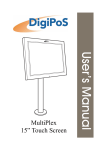
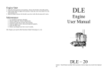
3. Unpacking and checking the parts
** WINPOS SYSTEM **
WD-202 DISPLAY
2.Long Support 3.Short Support
4.Base Section
ADAPTOR
1.Display Panel
6.Adapter
5.RS232C Cable(Link to PC/Host)
Notes: Make sure no parts are missing or damaged.
3
4. Interface
4.1 Specifications
Data transmission:
Synchronization:
Handshaking:
Signal level:
Baud rates:
Parity:
Bit length:
Stop bits:
Serial
Asynchronous
DTR / DSR
MARK = -3 to –15 V (logic “1”)
SPACE = +3 to +15 V (logic “0”)
9600 bps
None
8 bits
1 or more
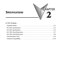
4.2 Interface connector (On the bottom of the base section)
●Interface connector on the bottom of Pole Display Base (standard )
CN2
CN3
CN6
CN2: RS-232C connects to PC/Host
CN3: Connect to display panel
CN6: Power supply connector
CN1,CN4, CN5: No used
Power Supply Connectors
CN6 / Connector type: DC jack (5.5/2.1)
Interface connector on the bottom of Pole Display Base (option )
CN5
CN4
CN3
CN2:Power input connector from adapter
CN3: RS-232C connect to printer ( reserved )
CN4: Connect to display panel
CN5: RS-232C connect to PC/Host
4
CN2
4.3 Power Supply Connectors
CN6 / Connector type: DC jack (5.5/2.1)
4.4 RS232C link to PC/HOST connector
CN2 / Connector type: D-sub 9 pin female
5
6
No
2
3
4
5
6,8
Signal
RXD
TXD
DSR
GND
DTR
1
9
Pin assignment
Direction
From PC/Host to display
From display to PC/Host-
1
6
Function description
Receive data
Signal ground
Display ready Signal
4.5 RS232C link to display panel
CN3 / Connector type: Phone-jack 10P/8C
10
1
Pin assignment
No
1
2,3
4,5
6
7
8
9
10
Signal
NC
V+
GND
DSR
DTR
RXD
TXD
NC
Direction
To display panel
From display panel
To display panel
From display panel
-
Function description
Not connect
Power input ( 9 – 33 Vdc )
Signal ground
PC/Host ready signal
Printer ready signal
Send data to display
No use
Not connect
5
5. Command List
COMMAND
[Name]
[Format]
Command name.
<>H indicates hexadecimal, <> indicates decimal, [ ]k
indicates k times repeat to control code and frequency.
Gives the allowable range for set argument and data.
Explain command function.
Complement particular.
Gives important information on the setting and used of
printer command, if necessary.
[Range]
[Description]
[Complement]
[Note]
Command
US
ESC q A
SO
Code
<1F>H
<1B>H<71>H/<41>H”d1
d30” 0D
<1B>H<71>H/<42>H”d1
d30” 0D
<1B>H<71>H/<43>H”d1
d30” 0D
<1B>H<71>H/<44>H”d1
d30” 0D
<1B>H<71>H/<45>H”d1
d30” 0D
<1B>H<71>H/<46>H”d1
d30” 0D
<0E>H
DC4
<14>H
ESC q B
ESC q C
ESC q D
ESC q E
ESC q F
–
–
–
–
–
–
Name and description
Clear display
Show string data
“d1 – d30” to display line 1.
Show string data
“d1 – d30” to display line 2.
Show string data
“d1 – d30” to display line 3.
Show string data
“d1 – d30” to display line 4.
Show double-height string data
“d1 – d30” to display line 1 and line 2.
Show double-height string data
“d1 – d30” to display line 3 and line 4.
Set double-width character mode,
This code must be inside string data “d1 –
d30”.
Cancel double-width character mode,
This code must be inside string data “d1 –
d30”.
6
Appendix A. Character code tables
0
1
2
3
4
5
6
7
8
9
A
B
C
D
E
F
00
10
NUL
DLE
20 30
SP 0
!
1
2
“
#
3
EOT
$
4
ENQ
%
5
&
6
7
‘
(
8
HT
)
9
LF
*
:
ESC +
;
,
<
CR GS =
.
>
US / ?
40
@
A
B
C
D
E
F
G
H
I
J
K
L
M
N
O
50
P
Q
R
S
T
U
V
W
X
Y
Z
[
\
]
^
_
60
`
a
b
c
d
e
f
g
h
I
j
k
l
m
n
o
70
p
q
r
s
t
u
v
w
x
y
z
{
|
}
~
SP
7
80
90 A0
B0
C0
D0
E0
F0
TWO BYTES CODE SYSTEM CHARACTERS
AREA
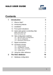
Appendix B: Customer Display Dimension
G
501 mm
225 mm
8
191 mm
281 mm
93 mm