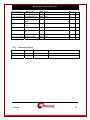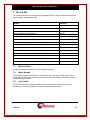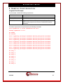
1
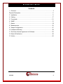
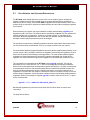
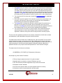
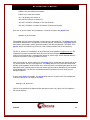
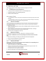
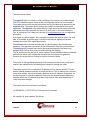
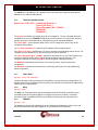
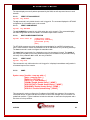
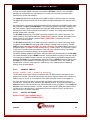
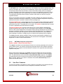
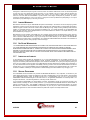
DT-2020i Inter-Networking Mediation Interface For SAM Concentrators User’s Manual RELEASE 11.X Manufacture & Distribution: 102 SW Orange Blossom Lake City, Florida 32025-1613 phone: 386-754-5700 email: [email protected] http://www.trdcusa.com http://www.datatekcorp.com DT-2020i User's Manual Contents 1 Overview ..........................................................................................................3 Physical Description..............................................................................................5 3 Installation ......................................................................................................11 4 Cabling...........................................................................................................17 5 Commands.....................................................................................................21 6 SNMP.............................................................................................................31 7 Alarms............................................................................................................34 8 Measurements ...............................................................................................35 9 Sample Configuration.....................................................................................37 10 Hardware Warranty.......................................................................................38 11 End-User License Agreement for Software...................................................38 12 Sales & Distribution.......................................................................................40 13 Author ...........................................................................................................40 01/21/08 2 DT-2020i User's Manual 1 OVERVIEW The DT-2020i is a mediation product, which allows the re-use of SAM concentrator endpoints on an IP infrastructure without any BNS equipment presence. The DT-2020i provides an integrated solution. It resides in a SAM64 or SAM128 concentrator and supports up to 128 ports. The DT2020i supports all of the current SAM port options and is compatible with the mediation function of the DT-40001. This device provides a TELNET over TCP path or a transparent TCP path for each user port on the SAM concentrator. These ports may then connect to an arbitrary IP host without an intermediary interface. While this is normally the case for asynchronous protocols, it is also true of synchronous protocols where the peer host has implemented the framing interface per the appropriate RFCs. Any IP Host IP Network DT-4000 Any IP Host DT2020i Endpoints Endpoints SAM The above configuration is not the only possible one. However, it does depict some of the networking capabilities of this device. A port on a SAM with a DT-2020i could be having a session directly with an IP host. A second port on the same SAM could be having a session directly with a device connected to a DT-4000. A third port could be connected to a fourth port on the same SAM, since local switching is done at the DT-2020i. 1 The DT-4000 is an internetworking device existing in BNS and IP, ATM, TDM or Frame Relay networks simultaneously. It acts like a SAM16, but supports IP inputs and higher port speeds. The DT-4000 communicates via Frame Relay, ATM, TDM or IP across the backbone network and becomes a stand-alone edge device in non-BNS networks. 01/21/08 3 DT-2020i User's Manual The DT-2020i is integrated into the supported SAM concentrator and therefore does not require a trunk connection. The connection to the IP network is via a 10BaseT interface. The network interface is active when the DT-2020i is in-service even if the connected SAM is not in service. Other protocols, such as SNMP, Telnet, and ARP are supported via the 10BaseT interface as well. 1.1 CLOSED USER GROUPS The DT-2020i supports the notion of Closed User Groups available in BNS networks. This is an important feature for protecting sensitive endpoints in a corporate-wide network without the burden of special “security servers”. Most IP terminal servers provide no protection of any kind with regard to per-port security. Their use in a sensitive environment would require external and expensive “security servers”. These external servers are not completely reliable because their protected network segment has multiple entry points. The DT-2020i solves all those issues by implementing a form of Closed User Groups for IP networks to provide a similar level of security as in a BNS Network. 1.2 HUNT GROUPS The DT-2020i supports the notion of Hunt Groups available in BNS networks. A Hunt Group is a set of ports that are arranged to receive calls to a common address. 1.3 MNEMONIC HOST NAMES The DT-2020i can maintain a set of mnemonic host names, analogous to the /etc/hosts file on both UNIX and Microsoft Windows platforms. This allows the DT-2020i to perform a translation between a user-provided name and its associated IP address and TCP port number. It is used for non-PDD originating ports. The use of a mnemonic name is optional; the DT-2020i will always accept an IP address in its base form. 1.4 TACACS+ RADIUS LOGIN SUPPORT The DT-2020i supports up to two TACACS+ RADIUS servers for login authentication. These are a primary, and a secondary, although each is individually enabled. The TACACS+ support is for either encrypted, or clear authorization. Encryption keys may contain spaces. 01/21/08 4 DT-2020i User's Manual 2 PHYSICAL DESCRIPTION 2.1 MODULE The DT-2020i is shipped from the factory with the slot “magic” jumper enabled. This configuration assumes the DT-2020i directly connects to a SAM. Do not remove this jumper. slot magic jumper 01/21/08 JP15 5 DT-2020i User's Manual 2.1.1 FACEPLATE Reset Mode Switch Enabl Diag Disab Red Fault Yellow Off Line Green On Line Datatek DSPQOOYAXX TN 2525 2020i LIGHT EMITTING DIODES (LED) The lights on the module faceplate are green, yellow, and red. They indicate on-line, off-line, and fault states, respectively. When the module circuitry detects an on-board fault, the red LED (fault) is lit. MODE SWITCH The Mode Switch supports three positions: Enabl, Diag and Disab. The Mode switch must be in the Enabl position for the DT-2020i to function properly. RESET BUTTON When the Reset button is pressed, the module buffers and registers are cleared, and the module application program is restarted. The module is taken out of service, and all connections are terminated. 01/21/08 6 DT-2020i User's Manual 2.2 CEY6 I/O BOARD The DT-2020i mates with the CEY6 I/O board in support of the DT-2020i connectivity options. The CEY6 I/O board contains all the necessary connectors the DT-2020i requires for currently available Console and LAN connections. Cables and adapters are available CEY6 Not Used Console RJ45 LAN Not Used 2.2.1 CONSOLE The DT-2020i Console interface may be used for console activities and the initial configuration. It assumes the connected device is configured as 9600 baud, 8 bits and no parity. 2.2.2 LAN The DT-2020i LAN interface is used for IP network connectivity. It simultaneously supports IPDSU style BNS trunks, and Internet peer-level protocols (e.g. IP, TCP, UDP, ICMP and SNMP). 01/21/08 7 DT-2020i User's Manual 2.3 FIELD UPGRADE AND SOFTWARE REGISTRATION The DT-2020i, when initially delivered, will need one or more software keys to activate the software. Software keys are also required when an optional individual feature packages are added to the device. Finally, when the DT-2020i is upgraded with revised software, one or more software keys are required to register the installed software and any feature packages registered for the device. When performing an upgrade, the revised software is initially downloaded by upgrade into a staging area and is not active. The software then is activated by a reboot. The new software will execute normally prior to registration. However, no backup, reloads, or upgrades can be performed. Module level parameters, such as the device IP address, may be changed and activated. Interface specific parameters cannot be changed. The procedure for performing a software registration has been mechanized. Manual procedures are error prone and not recommended. They are no longer covered in this user manual. The mechanized Software Upgrade Registration procedure allows simplified administration of one or more devices. When a quantity of devices are upgraded, manual software registration of each device has the potential of becoming increasingly tedious. The mechanized software upgrade registration process was designed to alleviate the problems associated with multiple device upgrades. It is also preferred for single device upgrades as it eliminates any potential for error. The new software is downloaded to the DT-2020i via the upgrade command. This may be performed for one or more devices. The “-r” option to the dtupgrade command will restart the device on the new software after the download completes successfully. It is highly recommended. In the alternative, the device may be downloaded without a restart and restarted at a later time during a scheduled maintenance window. Restarting the device on the new software prior to registration is required. After the restart, the devices will continue to operate normally on the new software without registration. Some operations interface functions are inhibited pending software registration. Below is an example of a typical upgrade invocation. Note the use of the “-r” option as it is recommended. upgrade –v –d –r –m2020i 192.168.0.226 dt_2020i.11.1 Mechanized registration is performed in three steps. Each of which does not require user intervention. The steps are as follows: 01/21/08 8 DT-2020i User's Manual 1. The getinfo utility is invoked on a file containing a list of devices to be administered. This file is called the master device list file and is typically named “dt_device.master”. The master device list file may have any name and it is provided as an argument to the getinfo utility. The master device list may also contain devices that do not require registration. The getinfo utility makes inquiry of each device in the master device list and creates a device information file named “dt_device.info” in the current directory. 2. The “dt_device.info” file is then sent via email to [email protected] for registration processing. 3. A file name “dt_device.register” file is returned via email to be used as input in the next step. A file named “dt_device.msgs” is a text file that may be displayed or printed showing the results of the registration function. 4. The setreg utility is invoked and uses the “dt_device.register” file provided as an argument. If no argument is provided, the file is assumed to be in the current directory. The setreg utility contacts each device that requires registration and have been assigned keys. One or more keys are installed during the dialogue. 5. The “dt_device.info” file and the “dt_device.register” file are deleted as they are transient and have no further value. Neither can be reused for the purpose of registration. However, the dt_device.info file may be used for inventory reports.. The source for the registration procedure is the inventory master device list file that is created, and maintained, by the administrator using their favorite text editor. The master device list file contains one IP address per line, with an optional TCP port, and an optional password override, to access the device. The IP address is the console connection address, and not necessarily the actual device IP address. Registration via the serial console is explicitly supported. Comments are allowed between addresses, and after addresses. A password override is only required if the default password of “initial” has been changed. The master device file line format is as follows: <IP ADDRESS> [<TCP PORT>] [-P<Password>] # Comment An example “dt_device.master” file follows: # This is a Sample master device list file “dt_device.master”. # Note that there is one device ( Connect IP Address ) per line. # TCP Port Override is allowed. Registration may use the serial console. # Password Override is allowed. # It is OK to have devices that do not need registration listed for inventory. # Comments in this file are preceded with a pound symbol. 01/21/08 9 DT-2020i User's Manual # Blank Lines are treated as comments. # Basic Line Format is as follows: 10.0.1.80 # Device at Location ‘A’ 192.168.7.82 # Device at Location ‘B’ 192.168.7.155 50001 # Example of TCP port Override. 192.168.7.156 50001 –pcustom1 # Example of Password Override. Once the “dt_device.master” file is prepared, it is used as an input to the getinfo utility. dtgetinfo dt_device.master This getinfo utility will collect information on each device in the master file. The getinfo utility will also make a determination if a registration is actually required. Consequently, the getinfo utility is also useful in performing inventory functions outside of the device registration. The output of the getinfo utility is a file named “dt_device.info” that is always created in the current directory. The file “dt_device.info” is attached to an email and sent to the address [email protected] registration procedure is performed and a file named “dt_device.register” is attached to return email to the original sender. A messages file named “dt_device.msgs” is also attached and may be printed as a report of the key generation function. After receiving the “dt_device.register” file, the setreg utility is invoked with the relative path of the “dt_device.register” file as it’s sole argument. The setreg utility will only contact the devices that actually need registration, and for which one or more keys were successfully generated. All of the appropriate keys, including a device key and multiple per port feature package keys, are installed by the setreg utility. The device is not restarted and this operation may occur during normal transport operation. A report utility devrep is available. The devrep utility uses the “dt_device.info” file to display the inventory information. The usage is as follows: devrep [-v] dt_device.info If the file is not specified, the dtdevrep utility attempts to use the “dt_device.info” file resident in the current directory. 01/21/08 10 DT-2020i User's Manual 3 I N S TA L L AT I O N This chapter contains the steps needed to install and configure the DT-2020i. 3.1 DT-2020I INSTALLATION CONSISTS OF: • inserting the CEY6 I/O distribution board in the SAM backplane slot • inserting the module in the corresponding shelf slot • cabling console and data ports When installing a DT-2020i: - To avoid damage to electronic components from ESD (Electro Static Discharge) always wear an ESD wrist strap. - To prevent damage to module circuitry, always insert the I/O board before inserting its corresponding module. Never remove the I/O board before removing the module. 3.1.1 INSERTING THE I/O BOARD The I/O board plugs into the backplane at the rear of the shelf; it is held in place by shrouds on the backplane pinfield, and secured with two screws. Insert the I/O board before inserting its corresponding DT-2020i. 1. Align the I/O board backplane connector with the backplane pinfield, and align the screw slots with the screw holes. 2. Slip the backplane connector onto the pins. The board should seat easily. If seating is difficult, the board may be canted or some pins may be bent. 3. Insert the screws, and tighten them securely. 3.1.2 REMOVING THE I/O BOARD Remove the I/O board only for relocation, replacement, or board-type confirmation. Requirement: The Module in the slot corresponding to the I/O board must be removed first. 1. Disconnect all cabling to I/O board ports, labeling the cable ends if appropriate. 2. Remove the screws holding the I/O board in place. 3. Carefully rock the board as you pull it out. 3.1.3 INSERTING THE DT-2020I Requirement: The I/O board for the module must be installed in its corresponding slot on the backplane at the rear of the shelf first. 1. Set the mode switch on the module faceplate to Disable. 2. With the module latch extended, carefully push the module all the way into the slot. The backplane pins slip into the module receptacle. 3. Close the latch to lock the module into position. 4. Move the mode switch on the module faceplate to Enable. 01/21/08 11 DT-2020i User's Manual 3.1.4 REMOVING THE DT-2020I MODULE You can remove and replace a DT-2020i in an operating SAM without damaging the module itself Requirement: I/O board for the module must still be in its corresponding slot on the backplane at the rear of the shelf. 1. If the mode switch is in the Enabl position, move it to Disab. 2. Open the latch on the module faceplate. 3. Pull the module straight out of the slot. 01/21/08 12 DT-2020i User's Manual 3.2 FIELD UPGRADE AND SOFTWARE REGISTRATION The DT-2020i, when initially delivered, will need one or more software keys to activate the software. Software keys are also required when an optional individual feature packages are added to the device. Finally, when the DT-2020i is upgraded with revised software, one or more software keys are required to register the installed software and any feature packages registered for the device. When performing an upgrade, the revised software is initially downloaded by dtupgrade into a staging area and is not active. The software then is activated by a reboot. The new software will execute normally prior to registration. However, no backup, reloads, or upgrades can be performed. Module level parameters, such as the device IP address, may be changed and activated. If a user port is taken out of service, the port cannot be restored. The procedure for performing a software registration has been mechanized. Manual procedures are error prone and not recommended. They are no longer covered in this user manual. The mechanized Software Upgrade Registration procedure allows simplified administration of one or more devices. When a quantity of devices are upgraded, manual software registration of each device has the potential of becoming increasingly tedious. The mechanized software upgrade registration process was designed to alleviate the problems associated with multiple device upgrades. It is also preferred for single device upgrades as it eliminates any potential for error. The new software is downloaded to the DT-2020i via the dtupgrade command. This may be performed for one or more devices. The “-r” option to the dtupgrade command will restart the device on the new software after the download completes successfully. It is highly recommended. In the alternative, the device may be downloaded without a restart and restarted at a later time during a scheduled maintenance window. Restarting the device on the new software prior to registration is required. After the restart, the devices will continue to operate normally on the new software without registration. Some operations interface functions are inhibited pending software registration. Below is an example of a typical dtupgrade invocation. Note the use of the “-r” option as it is recommended. dtupgrade –v –d –r –i –mDT-2020i 10.0.1.150 dt_2020i.10.1 Mechanized registration is performed in three steps. Each of which does not require user intervention. 01/21/08 13 DT-2020i User's Manual The steps are as follows: The dtgetinfo utility is invoked on a file containing a list of devices to be administered. This file is called the master device list file and is typically named “dt_device.master”. The master device list file may have any name and it is provided as an argument to the dtgetinfo utility. The master device list may also contain devices that do not require registration. The dtgetinfo utility makes inquiry of each device in the master device list and creates a device information file named “dt_device.info” in the current directory. The “dt_device.info” file is then sent via email to [email protected] for registration processing. A file name “dt_device.register” file is returned via email to be used as input in the next step. A file named “dt_device.msgs” is a text file that may be displayed or printed showing the results of the registration function. The dtsetreg utility is invoked and uses the “dt_device.register” file provided as an argument. If no argument is provided, the file is assumed to be in the current directory. The dtsetreg utility contacts each device that requires registration and have been assigned keys. One or more keys are installed during the dialogue. The “dt_device.info” file and the “dt_device.register” file are deleted as they are transient and have no further value. Neither can be reused for the purpose of registration. However, the dt_device.info file may be used for inventory reports.. The source for the registration procedure is the inventory master device list file that is created, and maintained, by the administrator using their favorite text editor. The master device list file contains one IP address per line, with an optional TCP port, and an optional password override, to access the device. The IP address is the console connection address, and not necessarily the actual device IP address. Registration via the serial console is explicitly supported. Comments are allowed between addresses, and after addresses. A password override is only required if the default password of “initial” has been changed. The master device file line format is as follows: <IP ADDRESS> [<TCP PORT>] [-P<Password>] # Comment An example “dt_device.master” file follows: 01/21/08 14 DT-2020i User's Manual # This is a Sample master device list file “dt_device.master”. # Note that there is one device ( Connect IP Address ) per line. # TCP Port Override is allowed. Registration may use the serial console. # Password Override is allowed. # It is OK to have devices that do not need registration listed for inventory. # Comments in this file are preceded with a pound symbol. # Blank Lines are treated as comments. # Basic Line Format is as follows: 10.0.1.80 # Device at Location ‘A’ 192.168.7.82 # Device at Location ‘B’ 192.168.7.155 50001 # Example of TCP port Override. 192.168.7.156 50001 –pcustom1 # Example of Password Override. Once the “dt_device.master” file is prepared, it is used as an input to the dtgetinfo utility. dtgetinfo dt_device.master This dtgetinfo utility will collect information on each device in the master file. The dtgetinfo utility will also make a determination if a registration is actually required. Consequently, the dtgetinfo utility is also useful in performing inventory functions outside of the device registration. The output of the dtgetinfo utility is a file named “dt_device.info” that is always created in the current directory. The file “dt_device.info” is attached to an email and sent to the address [email protected]. The registration procedure is performed and a file named “dt_device.register” is attached to return email to the original sender. A messages file named “dt_device.msgs” is also attached and may be printed as a report of the key generation function. After receiving the “dt_device.register” file, the dtsetreg utility is invoked with the relative path of the “dt_device.register” file as it’s sole argument. The dtsetreg utility will only contact the devices that actually need registration, and for which one or more keys were successfully generated. All of the appropriate keys, including a device key and multiple per port feature package keys, are installed by the dtsetreg utility. The device is not restarted and this operation may occur during normal transport operation. 01/21/08 15 DT-2020i User's Manual A report utility dtdevrep is available. The dtdevrep utility uses the “dt_device.info” file to display the inventory information. The usage is as follows: dtdevrep [-v] dt_device.info If the file is not specified, the dtdevrep utility attempts to use the “dt_device.info” file resident in the current directory. 01/21/08 16 DT-2020i User's Manual 4 CABLING This section provides information on cabling the DT-2020i console and data ports. Consult the following table for ordering information regarding all of the cabling options shown in this section. Depending upon access availability some of the following cables will be needed to set up DT2020i console and data ports. Cable / Adapter Description Mod – DB9 adapter 8-pin mod to DB9 M D8AH-M adapter 25-pin M to mod socket D8AH-F adapter 25-pin F to mod socket D8AG-M adapter 25-pin M to mod socket D8AG-F adapter 25-pin F to mod socket Console (special wiring) 8-pin mod to 8-pin mod (special) Console (standard wiring) 8-pin mod to 8-pin mod (standard) CAT5 cable 8-pin mod to 8-pin mod (shielded) Note: Use an AG adapter to talk to a terminal and an AH adapter to talk to a modem. The AH adapter will be used to terminate the cable and will be attached to the appropriate device. The attached device will determine the gender of the AH adapter. 01/21/08 17 DT-2020i User's Manual 4.1 CONSOLE CABLING The DT-2020i is managed through the console port by a terminal, PC, dial-up modem, or BNS asynchronous connection. Network administrators can access the console port through the StarKeeper® II NMS. Console cables are available and are required for console connection to TY12 and MSM modules, SAM64/504 Multiplexors and connection through an Ortronics distribution patch panel (see figure). Depending upon access availability, the following will be needed to setup a DT-2020i console connection. • A DT-2020i circuit pack and CEY-6 I/O Board • Either a straight modular or console cable will be used to connect from the console port into either an AH adapter or into a 258B adapter • The AH adapter will be used to terminate the cable and will be attached to the appropriate device. The attached device will determine the gender of the AH adapter. AH SAM8/16 AH Modem AH Patch Panel console cable special wiring AH PC or Dumb Term console cable special wiring 258B straight mod cable D T 20 20i 01/21/08 C E Y 6 straight mod cable Console straight mod cable LAN TY / SAM64 18 DT-2020i User's Manual DATA CABLING A Shielded-Twisted-Pair CAT5 cable is attached to the LAN port of the I/O board and will allow for cabling either into a 10BaseT hub or router. D T 20 20i 01/21/08 C E Y 6 Console STP CAT5 Cable 10 Base-T Hub STP CAT5 Cable Router LAN 19 DT-2020i User's Manual 4.2 DT-2020I SAM SETUP The DT-2020i is easily configured. First, configure the IP address, a Gateway Router IP address (if required) and an SNMP trap manager address (optional). Refer to the command section for additional information login passwd=initial local ipaddr=135.17.59.206 submask=255.255.255.0 gateway ipaddr=135.17.59.1 rs SAM mod rs dt2020 Note: In the initial configuration above, the SAM type was not entered. That is because the DT2020i will determine the type automatically from the attached SAM. Suppose port 1 of the SAM is to be a port which can originate a call, attached to a device at 9600 baud, asynchronous, 8 bits, no parity with a “double break” disconnect. The configuration command sequence is as follows: port 1 type=orig prot=async baud=9600 attn=2brk rs SAM port 1 Note: Many options were left at their default value. This is merely a sample configuration. Suppose port 2 is to be a port which can receive a call. It too is attached to a device at 9600 baud, asynchronous, 8 bits, no parity. The call is to be received on a hunt group TCP port 51000. The configuration sequence is as follows: port 2 type=rcv prot=async baud=9600 hport=51000 rs SAM p 2 Now suppose that port 10 is to be added to the hunt group along with port 2: same parameters. port 10 type=rcv prot=async baud=9600 hport=51000 rs SAM p 10 Other options, such as making the port "Permanently Active", synchronous options, Closed User Groups, Flow control, etc. are assigned by using their tag format as listed in the commands section. 01/21/08 20 DT-2020i User's Manual 5 COMMANDS 5.1 MODULE LEVEL COMMANDS The module-level commands are listed below. Not all commands are visible all the time. Should the unit be logged out, only the login command would be visible. A reboot places the unit in the logged out mode. The OA&M port is StarKeeper compatible for future integration. Please note that four commands - remove, restore, vfy, and dmeas – use “dt2020” (not “dt2020i”) as a command object. 5.1.1 LOGIN Syntax: login passwd=<password> (default password is: initial) The login command is a security command required for accessing the bulk of the Module command set. It is only available when the user is logged off. The password must contain between one and seven alphanumeric characters. The typed password is case insensitive and is not echo-suppressed. Special characters are not allowed. 5.1.2 LOGOUT Syntax: logout The logout command returns the Universal Trunk to its logged out mode thus preventing unauthorized access. 5.1.3 CHANGE PASSWORD Syntax: chgpass old=<password> new=<password> confirm=<password> The chgpass command allows the user to change a previously configured password. The old password is the one currently in effect. The new and confirm passwords should be identical. The password must contain between one and seven alphanumeric characters and is case insensitive where special characters are not allowed. All arguments are required to complete the command. 5.1.4 LOCAL Syntax: local mac=<MAC addr> ipaddr=<IP address> submask=<submask> The local or lo command sets the IP address of the DT-2020i to facilitate IP communication. The MAC address is a fixed attribute for each unit that should be set only to the value specified at the factory. However, in cases where a spare unit is replacing a failed DT-2020i, configuring the replacement unit with the same MAC address as the failed unit will eliminate the need for address resolution. The ipaddr is the IP address of this unit. The submask is the subnet mask of this unit with a default value of 8 bits (255.255.255.0). The IP address and subnet mask are used by the unit to determine whether the IP address of an outgoing packet is on the same LAN segment, or if a gateway hop is required. 5.1.5 GATEWAY Syntax: gateway ipaddr=<IP address> The gateway or ga command identifies the IP address of the local gateway router, if any. If the remote device resides on a different LAN, the gateway is the first hop the data travels through to reach the remote device. 01/21/08 21 DT-2020i User's Manual The ipaddr is the IP address of the gateway router to be used when a packet’s destination IP address is on a different LAN segment. 5.1.6 TACACS+ RADIUS SERVERS Syntax: tac < PRI | SEC > [ ipaddr=<IP Address> ] [ port=<TCP Port> ] [ key=”Encryption Key” | NONE ] [ ENABLE ] [ DISABLE ] The tacplus command is only visible when the unit is logged in. The tac command allows the configuration of up to two TACACS+ RADIUS servers for the device. the servers are used as a primary server and a secondary server, although they may be individually disabled. The < PRI | SEC > syntax specifies which server is to be configured. A server may not be configured while enabled The [ ipaddr=<IP Address> ] specifies the IP address of the configured server. The [ port=<TCP Port> ] specifies the TCP port to use when communicating with the server. The TACACS+ service defaults to TCP port 49, but any port may be specified. The [ key=”Encryption Key” | NONE ] specifies an encryption key to use. The Encryption key must be enclosed in double quotes, and the double quotes are not part of the key. If no encryption is desired, the value of NONE is used to designate unencrypted service. The ENABLE command allows this server to be used for service, and prevents further configuration. The DISABLE command prevents this server from being used for service, and subsequently allows configuration. 5.1.7 ICMP “PING” Syntax: ping <IP address> The ping command verifies the ability of the DT-2020I to communicate with a remote device, by sending Internet Control Message Protocol (ICMP) echo packets to the specified IP address and listening for echo reply packets. 5.1.8 HELP Syntax: help The help or ? command without arguments displays the entire DT-2020i command set and command syntax for the mode (logged out or logged in) the unit is currently in. Individual command syntax is available when the help command is followed by the command name. 5.1.9 VERSION Syntax: ver The version or ver command displays the current software and database revisions of the unit and is only visible when the user is logged in. The command has no arguments. 01/21/08 22 DT-2020i User's Manual 5.1.10 REBOOT Syntax: reboot The reboot command resets the unit, which allows physical attributes to be set, and the command has no arguments. It is only visible when the unit is logged in. After reboot, the OA&M interface returns to the logged-out mode. 5.1.11 REMOVE DT-2020I MODULE Syntax: remove dt2020 The remove dt2020 command is only visible when the unit is logged in. The command has no additional arguments. The command takes the unit out of service. This command must be performed before any module level configuration changes can occur. 5.1.12 REMOVE SAM MODULE Syntax: remove SAM MOD The remove SAM MOD command is only visible when the unit is logged in. The command has no additional arguments. The command takes the SAM out of service. 5.1.13 RESTORE DT-2020I MODULE Syntax: restore dt2020 The restore dt2020 command is only visible when the unit is logged in. The command has no additional arguments. It returns the unit to service. If any physical attribute was changed on the unit, including the MAC address, the unit will be automatically rebooted by this command. 5.1.14 RESTORE SAM MODULE Syntax: restore SAM MOD The restore SAM MOD command is only visible when the unit is logged in. The command has no additional arguments. It returns the SAM to service. 5.1.15 CLEAR Syntax: clr The clear command is only visible when the unit is logged in. There are no arguments. It sets all the measurements and error counters to zero. 5.1.16 DT-2020I MODULE DISPLAY MEASUREMENTS Syntax: dmeas dt2020 The dmeas (dm) dt2020 command displays the current measurements for the unit and is only visible when the user is logged in. The command has no arguments. The report displays Packet, Frame, Error and Ethernet counters, plus specific per-protocol counters. Refer to the Measurements section. 5.1.17 SAM MODULE DISPLAY MEASUREMENTS Syntax: dmeas SAM MOD The dmeas SAM MOD command displays the current measurements for the SAM and is only visible when the DT-2020i is logged in. The command has no arguments. 01/21/08 23 DT-2020i User's Manual The report displays counts of packets processed by the SAM, as well as protocol errors in each direction. 5.1.18 VERIFY DT-2020I MODULE Syntax: vfy dt2020 The vfy command is only visible when the unit is logged in. The command displays the DT-2020i configuration in a formatted report on the console. 5.1.19 VERIFY SAM MODULE Syntax: vfy SAM MOD The vfy SAM MOD command is only visible when the unit is logged in. The command displays the SAM configuration and service state in a formatted report on the console. 5.1.20 HOST NAME ADMINISTRATION Syntax: host <host #> [name=<host name>] [ipaddr=<IP address>] [port=<TCP port>] [del] The DT-2020i supports mnemonic destination name translation for non-PDD originating user ports. These mnemonic names are translated into an IP address and TCP port during call setup. The host command is used to configure the translation table. The name field is a mnemonic for a destination up to nine characters in length. The ipaddr (of the host) and TCP port (on the host) parameters specify the translation to be performed during call setup. If the parameter del is used, the entry is deleted. 5.1.21 VERIFY HOST Syntax: vfy host This command is only visible when the unit is logged in. It displays host-address configuration in a formatted report on the console. 5.1.22 SNMP Syntax: snmp [ ipaddr= < trap mgr addr > ] [ port= < trap mgr port > ] [ PUBLIC=< YES | NO > ] [ CUG=<<+|-> CUG Number> ] [ COMM=”Double Quoted String” | NONE ] [ SYSCONTACT=”Double Quoted String” | NONE ] [ SYSNAME=”Double Quoted String” | NONE ] [ SYSLOC=”Double Quoted String” | NONE ] This command is used to configure the IP address of the SNMP trap manager. Since traps are unsolicited alarms, an agent can take the initiative to inform the manager of the occurrence of a predefined condition. Typical conditions include the cold-start or warm-start of equipment and a link-down or link-up condition. 01/21/08 24 DT-2020i User's Manual A single and multiple SNMP managers can access the DT-2020i. However, only one SNMP manager can be defined as the trap manager. As a result of this command, all traps will be directed to the chosen trap manager. The ipaddr field defines the IP address of the SNMP manager to which the traps are to be sent. The port field indicates the UDP port on that SNMP manager and defaults to the standard value of 162. Any combination of closed user group membership may be assigned to the SNMP interface using the parameter of cug=[+|-]<CUG Number>. The closed user group membership is displayed on the “verify module” output. Packets which have failed the SNMP Closed User Group Test are discarded. An alarm is not presented, but the failure is counted. The number may be displayed with the “dmeas mod” command. The DT-2020i allows setting of an SNMP community in addition to the public community. The public community is recognized when the [ PUBLIC=YES ] option is selected. Recognition of the public community is the default operation. When [ PUBLIC=NO ] is selected, the public community is not recognized. The DT-2020i allows setting of an SNMP community in addition to the public community. When configured, the DT-2020i will respond to SNMP manager requests in that community. The DT2020i will always respond to a request in the public community. The settable SNMP community is configured with the [ COMM=”Double Quoted String” | NONE ] option. The community may be in any case. The double quote encapsulation is not part of the community string. The settable community may be cleared by setting it to the keyword NONE. The MIB-II variables sysName, sysContact, and sysLocation may be initialized from the DT-2020i non-volatile database using the SNMP command. These variables are volatile in that they may be over-written by an SNMP manager. However, any change made by the SNMP manager will not impact the DT-2020i non-volatile database. Setting the value to NONE will clear the entries in the DT-2020i non-volatile database. Each field may be of 31 characters or less. The double quote encapsulation is not part of the respective variable. Any of the variables may be cleared by setting it to the keyword NONE. 5.1.23 CONSOLE TIMEOUT Syntax: timeout [OFF | <number of minutes>] The DT-2020i console uses a three-wire interface (RD, TD, GND), and the lead state of other signals is not relevant. This would imply that the only way to change the state of the console is to explicitly log in or log out, or via a reboot or reset, which forces the console to be logged out. For users who wish the console to automatically log off after a period of inactivity, there is a console timer. The console timer defaults to the disabled condition, and may be activated by the timeout command. This command is only visible when the console is logged in. The <number of minutes> value must be between 1 and 255, inclusive. When the DT-2020i determines a period of inactivity of the specified time, it automatically forces the console to log off. An INFO-level alarm (see sec. 7) is issued at that time. 5.1.24 INSTALL SOFTWARE Syntax: install [ key=<software key> ] [ fpkey=<software key>] 01/21/08 25 DT-2020i User's Manual The DT-2020i has a unique device software key, and multiple per port feature package keys. This section is included in the user manual for completeness. Under normal circumstances, only the mechanized utilities utilize this command. It may be executed manually under an emergency situation. Depending on the device, the keys may or may not be installed by the factory. The per port feature package keys my be added at any time, and do not affect the operation of the unit. The registration procedure does not require a restart to take effect on a device running the registered software. When executed without arguments, the install command will display the significant information needed to manufacture the device software key. The device IP address may also be required. No additional information is needed to create the feature package keys. The key=<software key> argument allows the entry of an eight-character alphanumeric software registration that is unique to this DT-xx8x device. If an invalid key is entered, a MINOR alarm is generated to that effect. The passwords are not altered. The rstpass command has been created to reset the passwords should that become necessary. The fpkey=<software key> argument allows the entry of an eight-character alphanumeric software registration that is unique to a port, and software feature package, on this DT-2020i device for the current software build. The specific feature package referenced by the software key becomes immediately available on the port without subsequent download. The <software key> has effect on only one port. Other ports on the device are not affected. If the same software feature package is needed on multiple ports, then multiple feature package keys are applied. The install command is always available. Please note that manual software installation is not recommended. The mechanized procedures in the section titled “Field Upgrade and Software Registration” should be used to install software. 5.1.25 RSTPASS ( RESETTING THE PASSWORD ) Syntax: rstpass [ key=<Password Key> ] The rstpass command is a command whose function is to reset the password(s) of the device to factory default values. This function was formerly performed as part of the software registration. Breaking it out into a separate command allows the software to be registered without password updates to take place. When invoked without arguments, the rstpass command will display the relevant information needed to generate the <Password Key>. This information is relayed to the technical support staff. The generated key is then used with the key=<Password Key> argument. The rstpass command should not be run between the time the key data is generated and the <Password Key> is utilized. Similarly, if the device is restarted, the resultant <Password Key> will not perform its intended function. 5.2 USER PORT COMMANDS The User Port interface commands are used to configure the operation of the individual RS-232 ports on the SAM. Their operation may be changed by commands in this section. 01/21/08 26 DT-2020i User's Manual 5.2.1 PORT COMMAND Syntax: port <PortNum>[type=<ORIG|RCV>] [dest=<ipaddr>] [dport=<Dest tcp_port>] [hport=<Hunt Group tcp_port>] [prot=<protocol>] [dxe=<DCE|DTE>] [baud=<baud_rate>] [enc=<NRZ|NRZI>] [ccar=<ON|OFF>] [fill=<MARK|FLAG>] [dbits=<5|6|7|8>] [pap=<ON|OFF>] [parity=<EVEN|ODD|NONE>] [stop=<1|1.5|2] [attn=<1BRK|2BRK|NONE|char>] [flow=<XON|HW|NONE>] [cug=<+|-><CUG_Num>] [crfix=<TRANS|NONULL>] This command configures an individual user port on the SAM. The <PortNum> is a number in the range from 1 to 128, inclusive, corresponding to the RS-232C end-user port being configured. A port either waits for an incoming call (type=RCV), or is an originator of a call (type=ORIG). The (optional) PDD for an ORIG-type port is defined by dest=<ipaddr> and dport=< Dest tcp_port>. A caller on an originating port without PDD information configured will be presented a user interface for “dialing”. When a port is a call receiver (listener), it is assigned a default port number value of 50,000 + SAM port number. The port may then be individually addressed at that address. However, when a specific TCP port is specified via the hport=<Hunt Group tcp_port> option, it is used in lieu of the default value. Multiple ports may share the same TCP port value. This is used to define a hunt group of ports. A connection that is directed to this TCP port value would select the next available physical port. The hport option may only be used with call receiver ports. The prot=<protocol> option defines the protocol used by the port. It may take on the values of Raw, Async, HDLC, SDLC, EBSC (EBCDIC BiSync), ABSC (Ascii BiSync), UNI (Uniscope BiSync), ALC (ALC BiSync), DDCMP, or VIP (VIP 7600 BiSync). The Raw protocol is asynchronous without the benefit of Telnet encapsulation. It is used for direct TCP connections to the user ports. Contact your sales representative with any other protocol requests. The dxe=< DCE | DTE > option specifies the clocking and signaling mode of the port. When the protocol is asynchronous, a dxe value of DCE implies that the port is operating as a modem device. It will assert CTS when presented with RTS. A value of DTE for the asynchronous protocol implies that the port is operating as a 2-wire DTE. When there is data available to send, it shall assert RTS and wait for CTS before sending the data. Please note that a four-wire DTE interface should be configured as DCE even though it uses a DTE asynchronous connector. When the protocol is synchronous (e.g. SDLC), a dxe value of DCE implies that the port should generate the clock signals. This would require the standard synchronous DCE cable adapter. A 01/21/08 27 DT-2020i User's Manual dxe value of DTE implies that the port should accept the clock signals presented. This would require the standard synchronous DTE cable adapter. When the protocol uses a recovered clock instead of a separate clock lead (e.g. SDLC NRZI two wire), the dxe value operates like the asynchronous protocol described above, since external clocking is not necessary. The appropriate asynchronous adapters should be used. The enc=<NRZ|NRZI> option specifies the physical encoding of the line. The default is NonReturn to Zero (NRZ). The ccar=<ON|OFF> field defines constant carrier. This is an option in which the CD (or DTR if the port is a DTE) EIA signal is maintained asserted regardless of call status. The pap=<ON|OFF> field defines a permanently active port. Setting this flag on means that the port is ready to communicate regardless of its DTR (or DCD if the port is a DTE) EIA signal. The fill=< MARK | FLAG > option indicates what kind of line fill should be applied between frames in the HDLC, or SDLC protocols. The baud=<baud_rate> determines the speed of the line. It is not required for synchronous DTE ports since the clocking is derived from the line. For asynchronous ports, the allowed values are 75, 110, 150, 300, 1200, 1800, 2400, 4800, 9600, 14400, 19200, 28800, 38400, 48000, 57600, or 115200. For synchronous DCE ports, the same rates apply up to and including 57600 (56K) baud. The dbits=<5|6|7|8> option specifies the number of data bits in an asynchronous port word. It excludes start, stop, and parity bits. The parity=<EVEN|ODD|NONE> option specifies the parity of an asynchronous port word. The stop=<1|1.5|2> option determines the number of stop bits for asynchronous ports. The attn=<1BRK|2BRK|NONE|char> sets the attention character. This is a character that when typed will interrupt the call to a local session. The 1BRK option specifies a single break. The 2BRK option specifies two breaks within a short period. The NONE option specifies that no attention character is defined. Finally, any ASCII character may be used as the attention. It should be entered in decimal ASCII representation. The flow=<XON|HW|NONE> option determines the flow control for the port. The XON option uses XON/XOFF in-band flow control characters. The HW option uses the CTS and RTS leads for flow control. Finally, indicating NONE may disable flow control. The cug=<+|-><CUG_num> option allows the inclusion or deletion of a Closed User Group in the list of CUGs assigned to the user port. The “+” will add the <CUG_num> to the CUG list. The “-” is used to delete the <CUG_num> from the list. The crfix=< TRANS | NONULL > option accommodates an anomaly in some early variants of telnet implementation on UNIX systems, which insert a NULL character in the data stream after a carriage return. Most end devices are not affected by this NULL character. However, some devices (e.g. the BNS control computer) have erroneous operation if these characters are received. The value TRANS indicates transparent operation, where all data received by the DT2020, including a NULL after a carriage return, is forwarded to the end device. The value of NONULL removes a NULL character immediately following a carriage return. No other NULL characters are affected. The default operation is transparent, and the crfix option may only be specified if the protocol selected is asynchronous. 5.2.2 REMOVE SAM PORT Syntax: remove SAM port <PortNum> 01/21/08 28 DT-2020i User's Manual The remove sam port command is only visible when the unit is logged in. <PortNum> may be a number in the range 1 through 128, and corresponds to a physical RS-232 port on the SAM. The command takes the port “Out of Service”. This command must be performed before any port-level configuration changes can occur. 5.2.3 RESTORE SAM PORT Syntax: restore SAM port <PortNum> The restore command is only visible when the unit is logged in. <PortNum> may be a number in the range of 1 through 128, and corresponds to a physical RS-232 port on the SAM. The command returns the port to service. 5.2.4 ADMINISTER CLOSED USER GROUP (CUG) Syntax: cug <CUG_Num> [ipaddr=<IP address>] [mask=<IP submask>] The cug command is only visible when the unit is logged in. The <CUG_num> parameter is the closed user group identifier used to assign the CUG to a user port (with the port command), and may be a value between 1 and 16, inclusive. A single IP address and subnet mask pair specifies each CUG. The ipaddr parameter is an address of an endpoint (or base address of a group of endpoints) to be allowed into the group. The ipaddr value ANDed with the submask value must agree with the caller’s or destination’s IP address ANDed with the same submask for a call to be allowed to or from a user port to which the CUG is assigned. Depending on the submask value, this allows an individual (submask=255.255.255.255), intermediate, or network-wide level of authorization. Setting the ipaddr value to 0.0.0.0 deletes any prior configuration for the <CUG_num>. A <CUG_num> may not be deleted if it is currently assigned to any user port. A list of all configured CUGs is reported via the vfy cug command. The list of closed user groups associated with a given user port is presented in response to the vfy SAM port command. 5.2.5 DISPLAY PORT MEASUREMENTS Syntax: dmeas SAM port <Port_num> The dmeas command is only visible when the unit is logged in. It displays the current port level measurements for the specified RS-232 port <Port_num> in a formatted report on the console. The value of <Port_num> is between 1 and 128, inclusive. 5.2.6 VERIFY SAM PORT CONFIGURATION Syntax: vfy SAM port <Port_Num> The verify command is only visible when the unit is logged in. The command displays the configuration of the port number specified. The range of <Port_Num> is between 1 and 128, inclusive. 5.2.7 VERIFY CLOSED USER GROUP Syntax: vfy CUG The verify command is only visible when the unit is logged in. The command displays the configuration of the Closed User Groups. 01/21/08 29 DT-2020i User's Manual 5.2.8 DISPLAY CONNECTIONS Syntax: dconn The dconn command is only visible when the unit is logged in. The command displays the connections between the user ports and their destinations. Only the user ports which are “talking” are displayed. The command takes no arguments. 5.2.9 DIAGNOSE PORT Syntax: diag port <port_num> <INT | EXT | ALL> The diag command is only visible when the unit is logged in. The command accepts arguments to specify a port on which to perform diagnostics. Two types of diagnostics are available. An internal port diagnostic checks the operation of the hardware exclusive of the cabling, connectors, and drivers. The external port diagnostic checks the operation of everything including the attached cable. The <port_num> is the RS-232 user port in the range of 1 through 128, inclusive. The port must be out of service to diagnose. The type of diagnostic is either INT for the internal tests, EXT for the external tests, or ALL for both the internal and external tests. 5.2.10 DISCONNECT PORT Syntax: disc SAM PORT <Port_num> The disc command is only visible when the unit is logged in. If the port is ‘in service’; any existing circuit established to the port will be dropped. This is useful in IP networks when the remote peer vanishes due to a remote reboot or a network error. It is essentially equivalent to a “remove/restore” command sequence. The value of <Port_num> is between one and the number of actual ports on the SAM. 5.2.11 DISPLAY EIA LEAD STATUS Syntax: deia SAM PORT <Port_num> The deia command is only visible when the unit is logged in. It displays EIA lead status for the selected RS-232 port. The value of <Port_num> is between one and the number of actual ports on the SAM. 01/21/08 30 DT-2020i User's Manual 6 SNMP The DT-2020i SNMP V1 agent supports a multitude of SNMP MIB variables, trap, set, and get operations. 6.1 SNMP VERSION 1 COMMANDS Command Operational Result Get Requests the values of one or more Management Information Base (MIB) variables. GetNext Enables MIB variables to be read sequentially, one variable at a time. Set Permits one or more MIB values to be updated. GetResponse Used to respond to a Get, GetNext, or Set. Trap Indicates the occurrence of a predefined condition. 6.2 DT-2020I SNMP MIB VARIABLE DATABASE RO = Read Only Variable R/W = Read Variable / Write Variable SIV = Storage is Volatile MIB Variable Number Name MIB Console Equivalent Access 1.3.6.1.2.1.1.1.0 SysDescr MIB-II Banner Message RO 1.3.6.1.2.1.1.2.0 SysObjectID MIB-II None RO 1.3.6.1.2.1.1.3.0 SysUpTime MIB-II None RO 1.3.6.1.2.1.1.4.0 SysContact MIB-II None R/W SIV 1.3.6.1.2.1.1.5.0 SysName MIB-II None R/W SIV 1.3.6.1.2.1.1.6.0 SysLocation MIB-II None R/W SIV 1.3.6.1.2.1.1.7.0 SysServices MIB-II None RO 1.3.6.1.2.1.4.1.0 IpForwarding MIB-II None RO 1.3.6.1.2.1.4.2.0 IpDefaultTTL MIB-II None RO 1.3.6.1.2.1.4.3.0 IpInReceives MIB-II Number of Ethernet Pkts Rcvd RO 1.3.6.1.2.1.4.4.0 IpInHdrErrors MIB-II Nbr of Packets w/Header Errs RO 1.3.6.1.2.1.4.5.0 IpInAddrErrors MIB-II Nbr Rx Packets w/Wrong Addr RO 1.3.6.1.2.1.4.6.0 IpForwDatagrams MIB-II None RO 1.3.6.1.2.1.4.7.0 IpInUnknownProtos MIB-II Nbr of Packets w/Unk Protocol RO 1.3.6.1.2.1.4.8.0 IpInDiscards MIB-II Nbr of Packets Disc due to Resource RO 1.3.6.1.2.1.4.9.0 IpInDelivers MIB-II Inferred from DMEAS counters RO 1.3.6.1.2.1.4.10.0 IpOutRequests MIB-II Number of Device Frames Transmitted RO 1.3.6.1.2.1.4.11.0 IpOutDiscards MIB-II Nbr of Port frames Disc due to RO 01/21/08 Notes 31 DT-2020i User's Manual Resource 1.3.6.1.2.1.4.12.0 IpOutNoRoutes MIB-II None RO 1.3.6.1.2.1.4.13.0 IpReasmTimeout MIB-II None RO 1.3.6.1.2.1.4.14.0 IpReasmReqds MIB-II None RO 1.3.6.1.2.1.4.15.0 IpReasmOKs MIB-II None RO 1.3.6.1.2.1.4.16.0 IpReasmFails MIB-II None RO 1.3.6.1.2.1.4.17.0 IpFragOKs MIB-II None RO 1.3.6.1.2.1.4.18.0 IpFragFails MIB-II None RO 1.3.6.1.2.1.4.19.0 IpFragCreates MIB-II None RO 1.3.6.1.2.1.4.21.0 IpRoutingDiscards MIB-II None RO 1.3.6.1.2.1.5.1.0 IcmpInMsgs MIB-II None RO 1.3.6.1.2.1.5.2.0 IcmpInErrors MIB-II ICMP Errors RO 1.3.6.1.2.1.5.3.0 IcmpInDestUnreach MIB-II None RO 1.3.6.1.2.1.5.8.0 IcmpInEchos MIB-II Nbr of Pings RO 1.3.6.1.2.1.5.9.0 IcmpInEchoReps MIB-II None RO 1.3.6.1.2.1.6.1.0 TcpRtoAlgorithm MIB-II None RO 1.3.6.1.2.1.6.2.0 TcpRtoMin MIB-II None RO 1.3.6.1.2.1.6.3.0 TcpRtoMax MIB-II None RO 1.3.6.1.2.1.6.4.0 TcpMaxConn MIB-II None RO 1.3.6.1.2.1.6.5.0 TcpActiveOpens MIB-II None RO 1.3.6.1.2.1.6.6.0 TcpPassiveOpens MIB-II None RO 1.3.6.1.2.1.6.7.0 TcpAttemptFails MIB-II None RO 1.3.6.1.2.1.6.8.0 TcpEstabResets MIB-II None RO 1.3.6.1.2.1.6.9.0 TcpCurrEstab MIB-II None RO 1.3.6.1.2.1.6.10.0 TcpInSegs MIB-II None RO 1.3.6.1.2.1.6.11.0 TcpOutSegs MIB-II None RO 1.3.6.1.2.1.6.12.0 TcpRetransSegs MIB-II None RO 1.3.6.1.2.1.6.13.X TcpConnTable Entries MIB-II None RO 1.3.6.1.2.1.6.14.0 TcpInErrs MIB-II None RO 1.3.6.1.2.1.6.15.0 TcpOutRsts MIB-II None RO 1.3.6.1.2.1.7.1.0 UdpInDatagrams MIB-II Derived from other Counts. RO 1.3.6.1.2.1.7.2.0 UdpNoPorts MIB-II Non-Peer and Spurious UDP errors RO 1.3.6.1.2.1.7.3.0 UdpInErrors MIB-II Frame Errors RO 1.3.6.1.2.1.7.4.0 UdpOutDatagrams MIB-II Frames Sent, Keep Alive Messages sent, etc. RO 01/21/08 32 DT-2020i User's Manual 1.3.6.1.2.1.7.5.X udpEntry Table MIB-II None RO 1.3.6.1.2.1.11.1.0 SnmpInPkts MIB-II None RO 1.3.6.1.2.1.11.3.0 SnmpInBadVersions MIB-II None RO 1.3.6.1.2.1.11.4.0 SnmpInBadCommunity MIB-II Names None RO 1.3.6.1.2.1.11.5.0 SnmpInBadCommunity MIB-II Uses None RO 1.3.6.1.2.1.11.6.0 SnmpInASNParseErrs MIB-II None RO 1.3.6.1.2.1.11.30.0 SnmpEnableAuthenTra MIB-II ps None R/W 1.3.6.1.2.1.11.31.0 SnmpSilentDrops MIB-II None RO 1.3.6.1.2.1.11.32.0 SnmpProxyDrops MIB-II None RO 6.3 SIV SUPPORTED TRAPS Alarm Text Severity Trap Type Notes None N/A ColdStart Generated when the unit starts up None N/A AuthFail SNMP Authorization Failure 01/21/08 33 DT-2020i User's Manual 7 ALARMS The following table reflects new alarm types generated by the DT-2020i. Alarms are visible at the console and by StarKeeper® II NMS. Alarm Severity Tx Error on 10BaseT. Check Physical Connection. MAJOR User Requested Reboot in Progress INFO Invalid Login Attempt. MINOR Invalid Password Change Attempt. MINOR *** TERM32 in SAM Slot #X Inserted. *** MINOR *** TERM32 in SAM Slot #X Removed. *** MINOR ** SAM504 detected – supported only as a SAM64 ** MINOR *** Unsupported SAM attached. Cannot restore *** MINOR Connectivity to SAMx has failed. MINOR ---> SAM Download Complete. <--- INFO Port XXX received a call from XXX.XXX.XXX.XXX outside CUG list. MINOR Installation Attempt Failed. MINOR Console session in-activity timeout. INFO Port XXX call disconnected. Half Open TCP error. INFO 7.1 MAJOR ALARMS A major alarm indicates a serious, service-degrading condition. 7.2 MINOR ALARMS A minor alarm indicates a secondary or transient error that is not likely to affect overall service unless multiple minor alarms are issued, in which case a serious condition exists that may affect overall system performance 7.3 INFO ALARMS An information alarm is a message that does not necessarily require attention. It typically is important for network administration, but does not adversely affect service. 01/21/08 34 DT-2020i User's Manual 8 MEASUREMENTS The following table lists the measurements available using the display measurements (dm) command. The base measurements are always displayed, while the error and exception counters are only displayed if nonzero. Interface Type Object Description 10BaseT Base DT2020i Number of 10BaseT Packets Received 10BaseT Base DT2020i Number of 10BaseT Packets Transmitted. V.35, RS-232 Base DT2020i Number of SAMx Frames Received. V.35, RS-232 Base DT2020i Number of SAMx Frames Transmitted. 10BaseT Except DT2020i Number of ICMP Echo Requests Received. 10BaseT Except DT2020i Number of ARP Requests Received (total). 10BaseT Error DT2020i Number of Ethernet Discards (Resource). V.35, RS-232 Error DT2020i Number of Port Discards (Resource). 10BaseT Error DT2020i Number of Late Collisions ( TX). 10BaseT Error DT2020i Number of Under-run. ( TX). 10BaseT Error DT2020i Number of packets which exceeded the Retry Limit ( TX ). 10BaseT Error DT2020i Number of Carrier Sense Lost ( TX ). 10BaseT Error DT2020i Number of Frame Collisions (RX). 10BaseT Error DT2020i Number of Receiver Overruns (RX). 10BaseT Error DT2020i Number of Receive CRC Errors. (RX). 10BaseT Error DT2020i Number of Short Frame Errors. (RX). 10BaseT Error DT2020i Number of Non-Aligned Frame Error. (RX). 10BaseT Error DT2020i Number of Frame Length Violations. (RX). 10BaseT Error DT2020i Number of Unsupported Protocol Frames. (RX). 10BaseT Error DT2020i Number of Invalid UDP frames. (RX). 10BaseT Error DT2020i Number of Rx Frames w/IP Header Checksum Errors. (RX). 10BaseT Error DT2020i Number of Rx Frames w/ICMP Checksum Errors. (RX). 10BaseT Error DT2020i Number of ICMP Unreachable Destination Messages (RX). 10BaseT Error DT2020i Number of Rx Frames from Non-Peer Entity. 10BaseT Error DT2020i Number of Unknown ICMP Messages. (RX). 10BaseT Error DT2020i Number of Packets lost from TTL Network Error. (RX). 10BaseT Error DT2020i Number of Packets with wrong IP Destination Address (RX). 01/21/08 35 DT-2020i User's Manual 10BaseT Error DT2020i Number of Rx Packets with Unknown ARP Operations. (RX). 10BaseT Error DT2020i Number of Bad ARP Reply Packets Received. 10BaseT Error DT2020i Number of RFC894 Packets with an Unknown protocol type field. (RX). 10BaseT Error DT2020i Number of 802.3 Frames with an Unknown protocol type field. (RX). RS-232,V.35 Error SAM Trunk Number of Frames aborted by CTS lost (TX). RS-232, V.35 Error SAM Trunk Number of Frames Under-Run. (TX). RS-232,V.35 Error SAM Trunk Number of Rx Frames Over-Run. RS-232,V.35 Error SAM Trunk Number of Rx Frames with CRC Errors. RS-232,V.35 Error SAM Trunk Number of Non-Aligned Frame Errors (RX). RS-232,V.35 Error SAM Trunk Number of Frame Length Violations. (RX). RS-232,V.35 Base SAM Trunk Number of DDS Packets Received from SAMx. RS-232,V.35 Base SAM Trunk Number of DDS Packets Sent to SAMx. SAMx Base SAM TCON Number of SAMx Module Protocol Errors (Rx). SAMx Base SAM TCON Number of SAMx Module Protocol Errors (Tx). SAMx Base SAM Port Number of Intervals w/Ingress data. SAMx Base SAM Port Number of Intervals w/Egress data. SAMx Base SAM Port Number of Intervals with Port Errors. SAMx Error SAM Port Number of Intervals w/URP Receiver Errors. SAMx Error SAM Port Number of Intervals w/URP Retransmissions. 01/21/08 36 DT-2020i User's Manual 9 S A M P L E C O N F I G U R AT I O N Originate Ports Example For this sample, consider the following requirements: IP Address 135.17.59.205 Subnet Mask 255.255.255.0 Gateway Address 135.17.59.1 SAM Ports 1-8 Originate, Not PAP, Not PDD, 9600 Baud, No Parity, 8 Data Bits, NRZ encoding, Asynchronous Protocol, Double Break Attention Sequence. The above requirements are implemented by the following commands: Local ipaddr=135.17.59.205 submask=255.255.255.0 Gateway ipaddr=135.17.59.1 Rs dt2020 Rs sam mod Port 1 type=orig prot=async baud=9600 dbits=8 parity=none attn=2brk Port 2 type=orig prot=async baud=9600 dbits=8 parity=none attn=2brk Port 3 type=orig prot=async baud=9600 dbits=8 parity=none attn=2brk Port 4 type=orig prot=async baud=9600 dbits=8 parity=none attn=2brk Port 5 type=orig prot=async baud=9600 dbits=8 parity=none attn=2brk Port 6 type=orig prot=async baud=9600 dbits=8 parity=none attn=2brk Port 7 type=orig prot=async baud=9600 dbits=8 parity=none attn=2brk Port 8 type=orig prot=async baud=9600 dbits=8 parity=none attn=2brk Rs sam p 1 Rs sam p 2 Rs sam p 3 Rs sam p 4 Rs sam p 5 Rs sam p 6 Rs sam p 7 Rs sam p 8 01/21/08 37 DT-2020i User's Manual 1 0 H A R D WA R E W A R R A N T Y The warranty period for the DT-2020i hardware shall be ninety (90) days from the date of shipment from TeleComp R&D or a designated manufacturer. Replacements and repairs are guaranteed for the longer of the remaining original warranty period or 30 days whichever is longer. 11 END-USER LICENSE AGREEMENT FOR S O F T WA R E This License Agreement ("License") is a legal contract between you and the manufacturer ("Manufacturer") of the system ("HARDWARE") with which you acquired software product(s) identified above ("SOFTWARE"). The SOFTWARE may include printed materials that accompany the SOFTWARE. Any software provided along with the SOFTWARE that is associated with a separate end-user license agreement is licensed to you under the terms of that license agreement. By installing, copying, downloading, accessing or otherwise using the SOFTWARE, you agree to be bound by the terms of this LICENSE. If you do not agree to the terms of this LICENSE, Manufacturer is unwilling to license the SOFTWARE to you. In such event, you may not use or copy the SOFTWARE, and you should promptly contact Manufacturer for instructions on return of the unused product(s) for a refund. 11.1 SOFTWARE LICENSE You may only install and use one copy of the SOFTWARE on the HARDWARE (unless otherwise licensed by Manufacturer). The SOFTWARE may not be installed, accessed, displayed, run, shared or used concurrently on or from different computers, including a workstation, terminal or other digital electronic device (“Devices”). Notwithstanding the foregoing and except as otherwise provided below, any number of Devices may access or otherwise utilize the services of the SOFTWARE. You may not reverse engineer, decompile, or disassemble the SOFTWARE, except and only to the extent that such activity is expressly permitted by applicable law notwithstanding this limitation. The SOFTWARE is licensed as a single product. Its component parts may not be separated for use on more than one HARDWARE. The SOFTWARE is licensed with the HARDWARE as a single integrated product. The SOFTWARE may only be used with the HARDWARE as set forth in this LICENSE. You may not rent, lease or lend the SOFTWARE in any manner. You may permanently transfer all of your rights under this LICENSE only as part of a permanent sale or transfer of the HARDWARE, provided you retain no copies, you transfer all of the SOFTWARE (including all component parts, the media and printed materials, any upgrades, this LICENSE and, if applicable, the Certificate(s) of Authenticity), and the recipient agrees to the terms of this LICENSE. If the SOFTWARE is an upgrade, any transfer must also include all prior versions of the SOFTWARE. Without prejudice to any other rights, Manufacturer may terminate this LICENSE if you fail to comply with the terms and conditions of this LICENSE. In such event, you must destroy all copies of the SOFTWARE and all of its component parts. 11.2 INTELLECTUAL PROPERTY RIGHTS The SOFTWARE is licensed, not sold to you. The SOFTWARE is protected by copyright laws and international copyright treaties, as well as other intellectual property laws and treaties. You may not copy the printed materials accompanying the SOFTWARE. All title and intellectual property rights in and to the content which may be accessed through use of the SOFTWARE is the property of the respective content owner and may be protected by applicable copyright or other intellectual property laws and treaties. This LICENSE grants you no rights to use such content. All rights not expressly granted under this LICENSE are reserved Manufacturer and its licensors (if any). 11.3 SOFTWARE SUPPORT SOFTWARE support is not provided by Manufacturer, or its affiliates or subsidiaries separate from the HARDWARE. For SOFTWARE support, please contact your supplier of the HARDWARE. Should you have any questions concerning this LICENSE, or if you desire to contact Manufacturer for any other reason, please refer to the address provided in the documentation for the HARDWARE. 11.4 EXPORT RESTRICTIONS You agree that you will not export or re-export the SOFTWARE to any country, person, or entity subject to U.S. export restrictions. You specifically agree not to export or re-export the SOFTWARE: (i) to any country to which the U.S. has 01/21/08 38 DT-2020i User's Manual embargoed or restricted the export of goods or services, which as of March 1998 include, but are not necessarily limited to Cuba, Iran, Iraq, Libya, North Korea, Sudan and Syria, or to any national of any such country, wherever located, who intends to transmit or transport the products back to such country; (ii) to any person or entity who you know or have reason to know will utilize the SOFTWARE or portion thereof in the design, development or production of nuclear, chemical or biological weapons; or (iii) to any person or entity who has been prohibited from participating in U.S. export transactions by any federal agency of the U.S. government. 11.5 LIMITED WARRANTY Manufacturer warrants that (a) the SOFTWARE will perform substantially in accordance with the accompanying written materials for a period of ninety (90) days from the date of shipment from TeleComp R&D or a designated manufacturer. Software support is limited to the hours of 9AM to 5PM ET Monday through Friday excluding TeleComp R&D observed holidays. An extended warranty may be purchased at additional cost. Any implied warranties on the SOFTWARE are limited to ninety (90) days. Some states/jurisdictions do not allow limitations on duration of an implied warranty, so the above limitation may not apply to you. Manufacturer's and its suppliers' entire liability and your exclusive remedy shall be, at Manufacturer's option, either (a) return of the price paid, or (b) repair or replacement of the SOFTWARE that does not meet this Limited Warranty and which is returned to Manufacturer with a copy of your receipt. This Limited Warranty is void if failure of the SOFTWARE has resulted from accident, abuse, or misapplication. Any replacement SOFTWARE will be warranted for the remainder of the original warranty period or thirty (30) days, whichever is longer. 11.6 NO OTHER WARRANTIES TO THE MAXIMUM EXTENT PERMITTED BY APPLICABLE LAW, MANUFACTURER AND ITS SUPPLIERS DISCLAIM ALL OTHER WARRANTIES, EITHER EXPRESS OR IMPLIED, INCLUDING, BUT NOT LIMITED TO IMPLIED WARRANTIES OF MERCHANTABILITY, FITNESS FOR A PARTICULAR PURPOSE AND NONINFRINGEMENT, WITH REGARD TO THE SOFTWARE AND THE ACCOMPANYING WRITTEN MATERIALS. THIS LIMITED WARRANTY GIVES YOU SPECIFIC LEGAL RIGHTS. YOU MAY HAVE OTHERS, WHICH VARY FROM STATE/JURISDICTION TO STATE/JURISDICTION. 11.7 LIMITATION OF LIABILITY To the maximum extent permitted by applicable law, in no event shall Manufacturer or its suppliers be liable for any damages whatsoever (including without limitation, special, incidental, consequential, or indirect damages for personal injury, loss of business profits, business interruption, loss of business information, or any other pecuniary loss) arising out of the use of or inability to use this product, even if Manufacturer has been advised of the possibility of such damages. In any case, Manufacturer's and its suppliers' entire liability under any provision of this License shall be limited to the amount actually paid by you for the SOFTWARE and/or the HARDWARE. Because some states/jurisdictions do not allow the exclusion or limitation of liability for consequential or incidental damages, the above limitation may not apply to you. 11.8 SPECIAL PROVISIONS The SOFTWARE and documentation are provided with RESTRICTED RIGHTS. Use, duplication, or disclosure by the United States Government is subject to restrictions as set forth in subparagraph (c)(1)(ii) of the Rights in Technical Data and HARDWARE Software clause at DFARS 252.227-7013 or subparagraphs (c)(1) and (2) of the Commercial HARDWARE Software-Restricted Rights at 48 CFR 52.227-19, as applicable. Manufacturer is TeleComp R&D or it’s designee manufacturer., 102 SW Orange Blossom, Lake City, Florida, 32025-1613. If you acquired the SOFTWARE in the United States of America, this Software License are governed by the laws of the State of Florida, excluding its choice of laws provisions. If you acquired the SOFTWARE outside the United States of America, local law may apply. This LICENSE constitutes the entire understanding and agreement between you and the Manufacturer in relation to the SOFTWARE and supercedes any and all prior or other communications, statements, documents, agreements or other information between the parties with respect to the subject matter hereof. 01/21/08 39 DT-2020i User's Manual 12 SALES & DISTRIBUTION CBM of America, Inc. Mr. Mike Stephens 1455 West Newport Center Drive Deerfield Beach, Florida 33442 800-881-8202 954-698-9104 Fax: 954-360-0682 www.cbmusa.com Datatek Applications, Inc. Mr. Dan Conklin 379 Campus Drive, Suite 100 Somerset, New Jersey 08873 732-667-1080 Fax: 732-667-1091 www.datatekcorp.com 13 AUTHOR Comments and Questions regarding this document or the products covered within this document should be addressed to the author Angel Gomez via email at [email protected] or via telephone at 386-754-5700. ©Copyright 2002, 2008 TeleComp Research & Development Corp. ©Copyright 1998, 2002 TeleComp Inc. All Rights Reserved Printed in USA Datakit and StarKeeper II NMS are registered trademarks of Lucent Technologies. 01/21/08 40