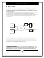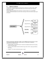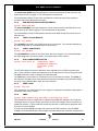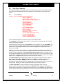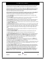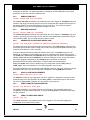
1
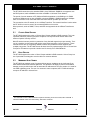
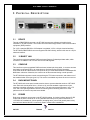
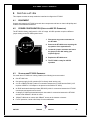
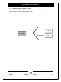
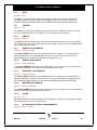
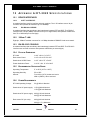
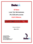
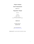
DT-2020
Inter-Networking Mediation
Interface
For SAM Concentrators
User’s Manual
VERSION 1.0.05
721 Route 202-206
Bridgewater, NJ 08807
fax: 908.218.1736
phone: 908.218.0500
email: [email protected]
http://www.datatekcorp.com
'78VHU
V0DQXDO
Contents
1 Safety Instructions ........................................................................................... 3
2 Overview .......................................................................................................... 5
3 Physical Description......................................................................................... 7
4 Installation........................................................................................................ 9
5 Cabling........................................................................................................... 13
6 Commands..................................................................................................... 17
7 SNMP............................................................................................................. 25
8 Alarms............................................................................................................ 28
9 Field Software Upgrade ................................................................................. 29
10 Measurements .............................................................................................. 30
11 Sample Configuration ................................................................................... 32
12 Appendix A:DT-2020 Specifications ............................................................. 33
13 Hardware Warranty....................................................................................... 35
14 Software End-User License Agreement...................................................... 35
06/11/01
Datatek Applications Inc.
2
'78VHU
V0DQXDO
1 SAFETY INSTRUCTIONS
!
The exclamation point within an equilateral triangle is intended to alert the user to the
presence of important operating and maintenance (servicing) instructions in the
literature accompanying the product.
When installing, operating, or maintaining this equipment, basic safety precautions should always be
followed to reduce the risk of fire, electric shock, and injury to persons, including the following:
q
q
q
q
q
q
q
q
q
q
Read and understand all instructions.
Follow all warnings and instructions marked on this product.
For information on proper mounting instructions, consult the User’s Manual provided with this product.
This product should only be operated from the type of power source indicated in the User’s Manual.
This unit is intended to be powered from either –48 V dc or AC voltage sources. See User’s Manual
before connecting to the power source.
The –48 V dc input terminals are only provided for installations in Restricted Access Areas locations.
Do not use this product near water, for example, in a wet basement.
Never touch uninsulated wiring or terminals carrying direct current or leave this wiring exposed. Protect
and tape wiring and terminals to avoid risk of fire, electric shock, and injury to service personnel.
To reduce the risk of electrical shock, do not disassemble this product. Service should be performed by
trained personnel only. Opening or removing covers and/or circuit boards may expose you to dangerous
voltages or other risks. Incorrect re-assembly can cause electric shock when the unit is subsequently
used.
For a unit intended to be powered from –48 V dc voltage sources, read and understand the following:
q
q
q
This equipment must be provided with a readily accessible disconnect device as part of the building
installation.
Ensure that there is no exposed wire when the input power cables are connected to the unit.
Installation must include an independent frame ground drop to building ground. Refer to User’s
Manual.
This symbol is marked on the Unit, adjacent to the
ground (earth) area for the connection of the ground
(earth) conductor.
q
q
This Equipment is to be Installed Only in Restricted Access Areas on Business and Customer
Premises Applications in Accordance with Articles 110-16, 110-17, and 110-18 of the National
Electrical Code, ANSI/NFPA No. 70. Other Installations Exempt from the Enforcement of the
National Electrical Code May Be Engineered According to the Accepted Practices of the Local
Telecommunications Utility.
For a unit equipped with an AC Wall Plug-In Unit, read and understand the following:
q
q
q
q
Use only the Sceptre, Model SA-0515A5U-2 or SINO American Electronic, Model SA10-0515U
(Globtek, Model TR9KA1500LCP-S) Wall Plug-In Unit shipped with this product.
Unplug this product from the wall outlet before cleaning. Do not use liquid cleaners or aerosol
cleaners. Use a damp cloth for cleaning.
Do not staple or otherwise attach the power supply cord to the building surfaces.
Do not overload wall outlets and extension cords as this can result in the risk of fire or electric
shock.
06/11/01
Datatek Applications Inc.
3
'78VHU
V0DQXDO
q
q
q
q
The socket outlet shall be installed near the equipment and shall be readily accessible.
The Wall Plug-In unit may be equipped with a three-wire grounding type plug, a plug having a third
(grounding) pin. This plug is intended to fit only into a grounding type power outlet. Do not defeat
the safety purpose of the grounding type plug.
Do not allow anything to rest on the power cord. Do not locate this product where the cord may be
abused by persons walking on it.
Unplug this product from the wall outlet and refer servicing to qualified service personnel under the
following conditions:
a)
When the powers supply cord or plug is damaged or frayed.
b)
If liquid has been spilled into the product.
c)
If the product has been exposed to rain or water.
d)
If the product does not operate normally by following the operating instructions. Adjust only
those controls that are covered by the operating instructions because improper adjustment of
other controls may result in damage and will often require extensive work by qualified
technician to restore the product to normal operation.
e)
If the product has been dropped or the cabinet has been damaged.
f)
If the product exhibits a distinct change in performance.
SAVE THESE INSTRUCTIONS
06/11/01
Datatek Applications Inc.
4
'78VHU
V0DQXDO
2 OVERVIEW
The DT-2020 is a mediation device, which allows for the re-use of SAM concentrator endpoints
on an IP infrastructure without any BNS equipment presence. The DT-2020 is an external unit
and provides up to 64 ports of service. The DT-2020 may be used with all types of SAM
concentrators, supports all of the current SAM port options, and is compatible with the mediation
1
function of the DT-4000 .
The DT-2020 provides a TELNET over TCP path or a transparent TCP path for each user port on
the SAM concentrator. These ports may then connect to an arbitrary IP host without an
intermediary interface. While this is normally the case for asynchronous protocols, it is also true of
synchronous protocols where the peer host has implemented the framing interface per the
appropriate RFCs.
DT-2020
Any
IP Host
Endpoints
SAM
IP
Network
DT-4000
Any
IP Host
Endpoints
The above configuration is not the only possible one. It depicts some of the networking
capabilities of the DT-2020. A port on a DT-2020 connected SAM could be having a session
directly with an IP host. A second port on a DT-2020 connected SAM could be having a session
directly with a device connected to a DT-4000. A third port could be connected to a fourth port on
the same SAM, since local switching is done by the DT-2020.
1
The DT-4000 is an inter-networking device, which may exist in BNS and IP, ATM, TDM or Frame Relay
networks simultaneously. It acts like a SAM16, but also supports IP inputs and higher port speeds. The DT4000 communicates via Frame Relay, ATM, TDM or IP across the backbone network, and becomes a
stand-alone edge device in non-BNS networks.
06/11/01
Datatek Applications Inc.
5
'78VHU
V0DQXDO
The DT-2020 connection to the attached SAM is via a SAM trunk. SAM8/16 concentrators use
2
the DDS protocol, while a SAM64 uses either a SAMSL or Universal Trunk Module .
The speed of a trunk between a DT-2020 and SAM is dependent on the SAM type. A SAM8
supports a 56Kbps trunk as does a SAMSL-connected SAM64. A SAM16 supports a 128Kbps
trunk. A Universal-Trunk connected SAM could have this link operate up to E1 rate.
The connection to the IP network is via a 10BaseT interface. The network interface is active when
the DT-2020 is in-service even if the connected SAM is not in service.
Other protocols, such as SNMP, Telnet, and ARP are supported via the 10BaseT interface as
well.
2.1
CLOSED USER GROUPS
The DT-2020 supports the notion of Closed User Groups available in BNS networks. This is an
important feature for protecting sensitive endpoints in a corporate-wide network without the
burden of special “security servers”.
Most IP terminal servers provide no protection of any kind with regard to per-port security. Their
use in a sensitive environment would require external and expensive “security servers”. These
external servers are not completely reliable because their protected network segment has
multiple entry points. The DT-2020 solves all those issues by implementing a form of Closed User
Groups for IP networks to provide a similar level of security as in a BNS Network.
2.2
HUNT GROUPS
The DT-2020 supports the notion of Hunt Groups available in BNS networks. A Hunt Group is a
set of ports that are arranged to receive calls to a common address.
2.3
MNEMONIC HOST NAMES
The DT-2020 can maintain a set of mnemonic host names, analogous to the /etc/hosts file on
both UNIX and Microsoft Windows platforms. This allows the DT-2020 to perform a translation
between a user provided name and its associated IP address and TCP port number. It is used for
non-PDD originating ports. The use of a mnemonic name is optional; the DT-2020 will always
accept an IP address in its base form.
2
The Universal Trunk is a BNS Module that replaces all existing trunks in the Node, MPC and SAM. It
interconnects BNS nodes over Frame Relay, ATM and IP networks.
06/11/01
Datatek Applications Inc.
6
'78VHU
V0DQXDO
3 PHYSICAL DESCRIPTION
3.1
DEVICE
Through a DB25 RS530 connector, the DT-2020 supports two software-selectable device
interfaces: V.35 and RS-232C. The female connector electrically presents a data communication
equipment (DCE) interface.
For V.35, a standard RS-530 to V.35 adapter is available. V.35 is a 34-pin electrical interface.
The DT-2020’s DB25 RS530 connector supports RS-232C directly, which in this case is a 25-pin
electrical interface.
3.2
10 BASE-T LAN
This interface requires a standard RJ45-terminated Category 5 twisted-pair data cable, which
connects to a 10BaseT hub or router on the local LAN segment.
3.3
CONSOLE
This interface requires a standard RJ45-terminated, twisted pair, data cable. It connects as data
terminating equipment (DTE) to an asynchronous device and uses RS-232C signaling.
Connection to the DT-2020 console is required for any DT-2020 administration or StarKeeper® II
NMS alarm collection. Otherwise, the console can be disconnected during normal operation.
The DT-2020 also supports console access through a TCP telnet connection, and makes use of
the standard telnet server port (port 23). This service is available only when the unit is in-service.
3.4
RACK-MOUNT PANEL
The DT-2020 rack-mount panel contains twelve slots to accommodate that number of DT-2020
units. Each rack-mount panel fits in a 19 inch or 23 inch EIA standard equipment rack (use
extension ears when mounting in a 23-inch rack). The rack-mount panel supports 1 inch, 1.75
inch, and 2 inch spacing between vertical rail mounting holes. Mounting ears for DT-2020
placements in the rack-mount panel are available.
3.5
POWER
Dual power interfaces are present on the DT-2020 faceplate. A circular interface labeled 5V DC
mates with the barrel connector of an AC (standard wall outlet) to DC power transformer for
115V/220V AC installations. A three position (accepting return, minus and ground power wires)
terminal block labeled 48V DC is commonly used in central office installations.
06/11/01
Datatek Applications Inc.
7
'78VHU
V0DQXDO
The DT-2020 is factory configured for 115V/220V AC usage. 48V DC operation requires a
different jumper setting on the DT-2020 system board. (See Installation Section)
3.5.1
STAND-ALONE AC POWER
For this application, a separate AC power supply is available. The power supply has a six-foot
cable that terminates with a barrel connector. The power supply plugs into a standard 115V or
220V AC outlet. The barrel connector plugs into the circular connector labeled 5V AC on the DT2020 faceplate.
3.5.2
RACK-MOUNT AC POWER
DT-2020 rack-mount AC power is the same as in the stand-alone DT-2020. This configuration
requires one AC power supply for each DT-2020 unit. However, it is recommended that your
equipment rack be outfitted with sufficient power strips to accommodate all of the AC power
supplies.
3.5.3
STAND-ALONE DC POWER
The stand-alone DT-2020 accepts DC power input directly from a 48V DC power source which
connects into the three position (accepting return, minus, and ground power wires) terminal block
labeled 48V DC on the DT-2020 faceplate. The terminal block connectors accommodate 10 awg
to 14 awg (American Wire Gauge) wire. A strain-relief clamp is available separately for DC wire
stabilization.
3.5.4
RACK-MOUNT DC POWER
The rack-mounted DT-2020 accepts DC power input directly from a 48V DC power source which
connects into one of two main, three position (accepting return, minus, and ground power wires)
terminal blocks labeled 48V DC on the rack-mount panel faceplate. Power is distributed to six
terminal blocks, vertically below each main terminal block, where each individual terminal block
powers a single DT-2020. Twelve DT-2020 units can be powered in this manner.
The terminal block connectors accommodate 10awg to 14awg (American Wire Gauge) wire. A
strain-relief clamp is available separately for DC wire stabilization
3.5.5
LED
The DT-2020 faceplate contains light emitting diodes (LEDs) used to report DT-2020 activity and
status.
LED Function
LED Color
LED Description
Transmit (Tx)
Yellow
10 Base-T Transmit Packet Indicator
Receive (Rx)
Yellow
10 Base-T Receive Packet Indicator
Link (LNK)
Green
10 Base-T Link Indicator
Collision (COL)
Red
10 Base-T Collision Indicator
Power (PWR)
Green
Unit Power Indicator
06/11/01
Datatek Applications Inc.
8
'78VHU
V0DQXDO
4
I N S TA L L AT I O N
This chapter contains the steps needed to install and configure the DT-2020.
4.1
EQUIPMENT
Unpack and inspect the DT-2020 units and other components and have on hand a #2 phillips and
medium-sized flathead screwdriver.
4.2
POWER CONFIGURATION (STEPS FOR 48V DC OPERATION)
The DT-2020 is factory configured for 115V AC usage. 48V DC operation requires a different
jumper setting on the DT-2020 system board.
1. Disconnect any power connectors to
the DT-2020.
2. Remove the DT-2020 cover exposing the
top portion of the system board.
3. Locate the jumper connector and move
the jumper to the 48V setting (see
adjacent figure).
4. Replace the DT-2020 cover.
5. The DT-2020 is ready for 48V DC
operation
4.3
STAND-ALONE DT-2020 EQUIPMENT
If a stand-alone DT-2020 unit is being installed, the following items are needed.
q
q
q
q
q
q
q
One DT-2020 unit.
One power supply for AC operation (DC is directly wired into the unit).
A V.35 or DB25 (RS-232C) cable for connection between the DT-2020 and the SAM. (V.35
requires a DB25 to V.35 adapter to be placed on the SAM or DT-2020)
An RJ45-terminated twisted-pair data (RS-232C) cable for connection between the DT-2020
console port and asynchronous device.
A category 5 RJ45-terminated twisted-pair data cable for connection between the DT-2020
and the local 10BaseT LAN hub or router.
10BaseT LAN hubs or routers with 10BaseT access to the Intranet or Internet.
For DC operation, a strain-relief clamp for wire stabilization
06/11/01
Datatek Applications Inc.
9
'78VHU
V0DQXDO
4.4
RACK-MOUNT DT-2020 EQUIPMENT
When installing DT-2020 units in a rack-mount configuration, it is necessary to gather the items
listed above for stand-alone DT-2020 installation, plus the following equipment.
q
q
q
q
q
An EIA standard 19-inch or 23-inch equipment rack with internal, vertical mounting rails. Hole
spacing on the vertical-mounting rail may be 1 inch, 1.75 inch or 2 inch. Use the dimension
specifications in the appendix to calculate how high the rack needs to be to support a
specified number of rack-mount panels. For example, seven rack-mount panels measuring
10.5 inches each will fit in a data equipment rack with internal mounting rails 75 inches in
height. This configuration will support a maximum of 84 DT-2020 units.
A rack-mount panel for each set of twelve DT-2020 units.
A pair of mounting ears for each DT-2020.
Strain relief clamps for DC wire stabilization.
A -48V DC power source for every 12 DT-2020s mounted in a rack.
4.5
STAND-ALONE INSTALLATION
4.5.1
AC ONLY
1. Attach the provided feet to the bottom of the unit.
2. Place the DT-2020 in the desired location, such as a shelf in a data equipment rack.
3. Plug one end of the RJ45-terminated category 5 twisted-pair data cable into the DT-2020
10BaseT LAN interface and the other into a 10BaseT LAN hub or router.
4. Plug one end of the RJ45-terminated twisted-pair data cable into the DT-2020 console
interface and the other into the port of the asynchronous device that will be used to configure
or manage the DT-2020.
5. Plug one end of the V.35 (requires DB25 to V.35 adapter) or RS232-C device cable into the
DT-2020 device interface and the other end into the existing SAM.
6. Plug the power supply into a standard 115V AC outlet and plug the barrel connector from the
power supply into the circular connector on the DT-2020 faceplate labeled 5V DC.
4.5.2
DC ONLY
1. Attach the provided feet to the bottom of the unit.
2. Fasten the strain-relief bracket to the side of the DT-2020.
3. Place the DT-2020 in the desired location, such as a shelf in a data equipment rack.
4. Plug one end of the RJ45-terminated category 5 twisted-pair data cable into the DT-2020
10BaseT LAN interface and the other into a 10BaseT LAN hub or router.
5. Plug one end of the RJ45-terminated twisted-pair data cable into the DT-2020 console
interface and the other into the port of the asynchronous device that will be used to configure
or manage the DT-2020.
6. Plug one end of the V.35 (requires DB25 to V.35 adapter) or RS232-C device cable into the
DT-2020 device interface and the other end into the existing SAM.
7. Run your 48V DC (return, minus and ground) wires from a central source through the strain
relief clamp for DC wire stabilization. On the DT-2020 faceplate, attach the return, minus and
06/11/01
Datatek Applications Inc.
10
'78VHU
V0DQXDO
ground wires to the return, minus and ground connections, respectively, of the terminal block
labeled 48V DC.
4.6
RACK-MOUNT INSTALLATION
4.6.1
AC ONLY
1. Prepare each DT-2020 for rack mounting by attaching the mounting ears to each side of the
DT-2020.
2. Fasten the twelve-slot rack-mount panel to a 19-inch equipment rack or use extension ears
for a 23-inch rack. Slide each DT-2020 with mounting ears into one of the twelve rack-mount
panel slots. Secure the DT-2020 to the rack mount panel with screws.
3. For each DT-2020, plug one end of the RJ45-terminated category 5 twisted-pair data cable
into the DT-2020 10BaseT LAN interface and the other end into a 10BaseT LAN hub or
router.
4. For each DT-2020, plug one end of the RJ45-terminated twisted-pair data cable into the DT2020 console interface and the other end into the asynchronous device.
5. For each DT-2020, plug one end of the V.35 (requires DB25 to V.35 adapter) or RS232-C
device cable into the DT-2020 device interface and the other end into the existing trunk cable
or BNS trunk I/O board.
6. Plug the power supply into a standard 115V AC outlet and the barrel connector from the
power supply into the circular connector on the DT-2020 faceplate labeled 5V DC.
4.6.2
DC ONLY
1. Prepare each DT-2020 for rack mounting by attaching the mounting ears to each side of the
DT-2020.
2. Attach the power distribution panel(s) to the rack-mount plate.
3. Make sure the rack mount panel rocker switches are set to the OFF position.
4. To the rack mount panel faceplate, fasten the strain relief clamp(s).
5. Fasten the twelve-slot rack-mount panel to a 19-inch equipment rack or use extension ears
for a 23-inch rack. Slide each DT-2020 with mounting ears into one of the twelve rack-mount
panel slots. Secure the DT-2020 to the rack mount panel with screws.
6. For each DT-2020, plug one end of the RJ45-terminated category 5 twisted-pair data cable
into the DT-2020 10BaseT LAN interface and the other end into a 10BaseT LAN hub or
router.
7. For each DT-2020, plug one end of the RJ45-terminated twisted-pair data cable into the DT2020 console interface and the other end into the asynchronous device.
8. For each DT-2020, plug one end of the V.35 (requires DB25 to V.35 adapter) or RS232-C
device cable into the DT-2020 device interface and the other end into the existing SAM.
9. Run the 48V DC (return, minus and ground) wires from a central source through the strain
relief clamp used for DC wire stabilization. On the rack mount panel, attach the return, minus
and ground wires to the return, minus and ground connections to one of the main terminal
blocks labeled 48 Vin. Power is distributed to six terminal blocks vertically below the main
terminal block and labeled 48 Vout. Each individual 48-Vout terminal block below the main 48
Vin terminal block powers a single DT-2020. This is accomplished by jumping short return,
minus and ground wires between the panel terminal block and the DT-2020 terminal block.
06/11/01
Datatek Applications Inc.
11
'78VHU
V0DQXDO
All terminal block connectors accommodate 10 awg to 14 awg wire. Strain relief clamps are
used for DC wire stabilization.
10. Make sure the rack mount panel rocker switches are set to the ON position.
06/11/01
Datatek Applications Inc.
12
'78VHU
V0DQXDO
5
CABLING
This section provides information on cabling the DT-2020 console and data ports. Consult the
following table for ordering information regarding all of the cabling options shown in this section.
Depending upon access availability, some of the following cables will be needed to setup DT2020 console and data ports.
Cable / Adapter
Description
258B adapter
50-pin M to 6 8-pin mod
CS25AS-MOD
50-pin 180-M to 34-pin V.35
V.35 to RS-232 adapter
Male 34 pin V.35 to Female DB25
V.35 to RS-232 adapter
Female 34 pin V.35 to Male DB25
Mod – DB9 adapter
8-pin mod to DB9 M
D8AH-M adapter
25-pin M to mod socket
D8AH-F adapter
25-pin F to mod socket
D8AG-M adapter
25-pin M to mod socket
D8AG-F adapter
25-pin F to mod socket
Console (special wiring)
8-pin mod to 8-pin mod
Straight mod cable
8-pin mod to 8-pin mod
CAT5 cable
8-pin mod to 8-pin mod (shielded)
Note: Use an AG adapter to talk to a terminal and an AH adapter to talk to a modem.
The AH adapter will be used to terminate the cable, and will be attached to the appropriate
device. The attached device will determine the gender of the AH adapter.
06/11/01
Datatek Applications Inc.
13
'78VHU
V0DQXDO
5.1
CONSOLE CABLING
The DT-2020 is managed through the console port by a terminal, PC, dial-up modem, or BNS
asynchronous connection. Network administrators can access the console port through the
StarKeeper® II NMS.
Console cables are available and are required for console connection to TY12 and MSM
modules, SAM64/504 Multiplexors, and connection through an Ortronics distribution patch panel
(see figure).
DT-2020
straight mod cable
AH
SAM8/16
straight mod cable
AH
Modem
straight mod cable
AH
Patch Panel
console cable
special wiring
AH
PC or
Dumb Term
console cable
special wiring
258B
Console
TY / SAM64
Specific instructions for configuration of SAM, TY12 and MSM asynchronous ports are available
in the appropriate BNS-2000 module reference guide. DT-2020-specific configuration
requirements are described herein.
•
Configure SAM, TY12 and MSM console connections as 9600 bps with 8 bits and no parity,
and use a DCE type cable.
•
Configure SAM and MSM console connections as type “host” and as a “pap” (permanently
active port).
•
Configure TY12 console connections as type “console”.
06/11/01
Datatek Applications Inc.
14
'78VHU
V0DQXDO
5.2
DT-2020 DATA (10 BASE-T LAN)
A Shielded Twisted-Pair CAT5 cable is attached to the 10 Base-T LAN port of the DT-2020. This
allows for cabling into either a 10BaseT hub or router.
DT-2020
06/11/01
STP CAT5 Cable
10 Base-T
Hub
STP CAT5 Cable
Router
LAN
Datatek Applications Inc.
15
'78VHU
V0DQXDO
5.3
DT-2020 SAM SETUP
The DT-2020 is easily configured. The first step involves giving it an IP address, a Gateway
Router IP address (if required), an SNMP trap manager address (optional), and the trunk speed.
Refer to the command section for additional information
login passwd=initial
local ipaddr=135.17.59.206 submask=255.255.255.0
gateway ipaddr=135.17.59.1
trunk phy=v35 speed=56k
rs SAM mod
rs dt2020
Note: In the initial configuration above, the SAM type did not need to be entered. This is because
the DT-2020 will determine the attached SAM type automatically.
Suppose port 1 of the SAM is to be a port which can originate a call. It is attached to a device at
9600 baud, asynchronous, 8 bits, no parity, with a “double break” disconnect.
The configuration of these attributes is as follows:
port 1 type=orig prot=async baud=9600 attn=2brk
rs SAM port 1
Note:
In this sample configuration, other options were left at their default values.
Suppose port 2 is to be a port which can receive a call. It too is attached to a device at 9600
baud, asynchronous, 8 bits, and no parity. The call is to be received on a hunt group TCP port
51000.
The configuration sequence is as follows:
port 2 type=rcv prot=async baud=9600 hport=51000
rs SAM p 2
Now suppose that port 10 is to be added to the hunt group along with port 2; same attributes.
port 10 type=rcv prot=async baud=9600 hport=51000
rs SAM p 10
Other options, such as making the port "Permanently Active", synchronous options, closed user
group assignments, flow control, etc. are assigned by using their tag format as specified in the
commands section.
06/11/01
Datatek Applications Inc.
16
'78VHU
V0DQXDO
6 COMMANDS
6.1
MODULE-LEVEL COMMANDS
The module-level commands are listed below. Not all commands are visible all the time. Should
the unit be logged out, only the login command would be visible. A reboot places the unit in the
logged out mode. The OA&M port is StarKeeper Compatible for future integration.
6.1.1
LOGIN
Syntax: login passwd=<password>
(default password is: initial)
The login command is a security command required for accessing the bulk of the Module
command set. It is only available when the user is logged off. The password must contain
between one and seven alphanumeric characters. The typed password is case insensitive and is
not echo-suppressed. Special characters are not allowed.
6.1.2
LOGOUT
Syntax: logout
The logout command returns the DT-2020 to its logged-out mode, thus preventing unauthorized
access.
6.1.3
CHANGE PASSWORD
Syntax: chgpass old=<password> new=<password> confirm=<password>
The chgpass command allows the user to change a previously configured password. The old
password is the one currently in effect. The new and confirm passwords should be identical. The
password must contain between one and seven alphanumeric characters and is case insensitive.
Special characters are not allowed. All arguments are required to complete the command.
6.1.4
LOCAL
Syntax: local mac=<MAC addr> ipaddr=<IP address> submask=<submask>
The local or lo command sets the IP address of the DT-2020 to facilitate IP communication.
The MAC address is a fixed attribute for each unit that should be set only to the value specified at
the factory. However, in cases where a spare unit is replacing a failed DT-2020, configuring the
replacement unit with the same MAC address as the failed unit will eliminate the need for address
resolution.
The ipaddr is the IP address of this unit. The submask is the subnet mask of this unit with a
default value of 8 bits (255.255.255.0). The IP address and subnet mask are used by the unit to
determine whether the IP address of an outgoing packet is on the same LAN segment, or if a
gateway hop is required.
6.1.5
GATEWAY
Syntax: gateway ipaddr=<IP address>
The gateway or ga command identifies the IP address of the local gateway router, if any. If the
remote device resides on a different LAN, the gateway is the first hop the data travels through to
reach the remote device.
The ipaddr is the IP address of the gateway router to be used when a packet’s destination IP
address is on a different LAN segment.
06/11/01
Datatek Applications Inc.
17
'78VHU
V0DQXDO
6.1.6
HELP
Syntax: help
The help or ? command without arguments displays the entire DT-2020 command set and
command syntax for the mode (logged out or logged in) the unit is currently in. Individual
command syntax is available when the help command is followed by the command name.
6.1.7
VERSION
Syntax: ver
The version or ver command displays the current software and database revisions of the unit
and is only visible when the user is logged in. The command has no arguments.
6.1.8
REBOOT
Syntax: reboot
The reboot command resets the unit, which allows physical attributes to be set. The command
has no arguments, and is only visible when the unit is logged in. After reboot, the OA&M interface
returns to the logged-out mode.
6.1.9
REMOVE DT-2020 MODULE
Syntax: remove dt2020
The remove dt2020 command is only visible when the unit is logged in. The command has no
additional arguments. The command takes the unit out of service. This command must be
performed before any module-level configuration changes can occur.
6.1.10
REMOVE SAM MODULE
Syntax: remove SAM MOD
The remove SAM MOD command is only visible when the unit is logged in. The command has
no additional arguments. The command takes the SAM out of service.
6.1.11
RESTORE DT-2020 MODULE
Syntax: restore dt2020
The restore dt2020 command is only visible when the unit is logged in. The command has no
additional arguments. It returns the unit to service. If any physical attribute was changed on the
unit, including the MAC address, the unit will be automatically rebooted by this command.
6.1.12
RESTORE SAM MODULE
Syntax: restore SAM MOD
The restore SAM MOD command is only visible when the unit is logged in. The command has no
additional arguments. It returns the SAM to service.
6.1.13
CLEAR
Syntax: clr
The clear command is only visible when the unit is logged in. There are no arguments. It sets all
the measurements and error counters to zero.
6.1.14
DT-2020 MODULE DISPLAY MEASUREMENTS
Syntax: dmeas dt2020
06/11/01
Datatek Applications Inc.
18
'78VHU
V0DQXDO
The dmeas (dm) dt2020 command displays the current measurements for the unit and is only
visible when the user is logged in. The command has no arguments.
The report displays Packet, Frame, Error and Ethernet counters plus specific per-protocol
counters. Refer to the Measurements section.
6.1.15
SAM MODULE DISPLAY MEASUREMENTS
Syntax: dmeas SAM MOD
The dmeas SAM MOD command displays the current measurements for the SAM and is only
visible when the DT-2020 is logged in. The command has no arguments.
The report displays counts of DDS packets sent to/from the SAM, as well as protocol errors in
each direction.
6.1.16
VERIFY DT-2020 MODULE
Syntax: vfy dt2020
The vfy dt2020 command is only visible when the unit is logged in. The command displays the
DT-2020 configuration in a formatted report on the console.
6.1.17
VERIFY SAM MODULE
Syntax: vfy SAM MOD
The vfy SAM MOD command is only visible when the unit is logged in. The command displays
the SAM configuration and service state in a formatted report on the console.
6.1.18
HOST NAME ADMINISTRATION
Syntax: host <host #>
[name=<host name>]
[ipaddr=<IP address>]
[port=<TCP port>]
[del]
The DT-2020 supports mnemonic destination name translation for non-PDD originating user
ports. These mnemonic names are translated into an IP address and TCP port during call setup.
The host command is used to configure the translation table.
The name field is a mnemonic for a destination up to nine characters in length. The ipaddr (of
the host) and TCP port (on the host) parameters specify the translation to be performed during
call setup. If the parameter del is used, the entry is deleted.
6.1.19
VERIFY HOST
Syntax: vfy host
This command is only visible when the unit is logged in. It displays host-address configuration in
a formatted report on the console.
6.1.20
SNMP
Syntax: snmp ipaddr=<Trap mgr addr> port=<Trap mgr port>
This command is used to configure the IP address of the SNMP trap manager. Since traps are
unsolicited alarms, an agent can take the initiative to inform the manager of the occurrence of a
predefined condition. Typical conditions include the cold-start or warm-start of equipment and a
link-down or link-up condition.
A single and multiple SNMP managers can access the DT-2020. However, only one SNMP
manager can be predefined as the trap manager. By administering this command, all traps will be
06/11/01
Datatek Applications Inc.
19
'78VHU
V0DQXDO
directed to the chosen trap manager. The port number should be configured for 162 on new
configurations, which is standard practice.
The ipaddr field defines the IP address of the SNMP manager to whom the TRAPs are to be
sent.
The port indicates the UDP port on that SNMP manager and defaults to the standard value of
162.
6.1.21
CONSOLE TIMEOUT
Syntax: timeout [OFF | <number of seconds>]
The DT-2020 console uses a three-wire interface (RD, TD, GND), and the lead state of other
signals is not relevant. This would imply that the only way to change the state of the console is to
explicitly log in or log out, or via a reboot or reset, which forces the console to be logged out.
For users who wish the console to automatically log off after a period of inactivity, there is a
console timer. The console timer defaults to the disabled condition, and may be activated by the
timeout command. This command is only visible when the console is logged in. The <number of
seconds> value must be between 15 and 255, inclusive. When the DT-2020 determines a period
of inactivity of the specified time, it automatically forces the console to log off. An INFO-level
alarm (see sec. 8) is issued at that time.
6.1.22
INSTALL SOFTWARE
Syntax: install [key=<registration key>]
The DT-2020 is shipped with the software pre-registered for the installed software. A registration
procedure must be performed after each upgrade to a new software release.
The install command is used to register the DT-2020 software. The command is available at all
times, since registration is required for a console login. When this command is used with no
argument, it provides the data needed to generate the registration key. The same command is
then used with the key value to register the software. The registration is performed after the new
software is made active with a module reboot command.
6.2
SAM INTERFACE COMMANDS
The SAM Interface commands are used to configure the connectivity to the attached SAM device.
Support is provided for DDS format direct serial trunks.
6.2.1
TRUNK
Syntax: trunk [phy=<v35|232>] [type=<DDS>] speed=<speed>]
[enc=<NRZ|INRZ|NRZI|INRZI>]
The trunk (or trk) command configures the serial-trunk interface to the SAM. The phy is
configured to match the physical interface of the SAM. Currently, the only type allowed is "DDS",
which implies a SAMSL trunk in a SAM64 (or a SAM8 or SAM16). The speed is configured for
the desired trunk speed, and can take on values of "t1", "768k", "512k", "256k", "128k", "56k",
"19200", "38400", or "9600". The RS232 interface may be used up to 56K, and the V.35 interface
to T1 speed. The type of attached SAM places a speed restriction on the trunk as well. The SAM8
will support 56K trunks. The SAM16 will support 128K trunks. The SAM64/504 will support a 56K
trunk if equipped with a SAMSL, or T1 if equipped with a Universal Trunk. The enc allows setting
the physical encoding. "NRZ" is "no return to zero" and is the standard encoding. "INRZ" is an
inverted version. "NRZI" is a different encoding scheme with the similar name of "non return to
zero inverted", and "INRZI" is the inverted version of that encoding. The default is "NRZ".
06/11/01
Datatek Applications Inc.
20
'78VHU
V0DQXDO
6.3
USER PORT COMMANDS
The User Port interface commands are used to configure the operation of the individual RS-232
ports on the DT-2020 attached SAM. Their operation may be changed by commands in this
section.
6.3.1
PORT COMMAND
Syntax: port <PortNum>[type=<ORIG|RCV>]
[dest=<ipaddr>]
[dport=<Dest tcp_port>]
[hport=<Hunt Group tcp_port>]
[prot=<protocol>]
[dxe=<DCE|DTE>]
[baud=<baud_rate>]
[enc=<NRZ|NRZI>]
[ccar=<ON|OFF>]
[fill=<MARK|SPACE>]
[dbits=<5|6|7|8>]
[pap=<ON|OFF>]
[parity=<EVEN|ODD|NONE>]
[stop=<1|1.5|2]
[attn=<1BRK|2BRK|NONE|char>]
[flow=<XON|HW|NONE>]
[cug=<+|-><CUG_Num>]
[crfix=<TRANS|NONULL>]
This command configures an individual user port on the attached SAM.
The <PortNum> is a number in the range from 1 to 64, inclusive, corresponding to the RS-232C
end-user port being configured.
A port either waits for an incoming call (type=RCV), or is an originator of a call (type=ORIG). The
(optional) PDD for an ORIG-type port is defined by dest=<ipaddr> and dport=< Dest tcp_port>.
A caller on an originating port without PDD information configured will be presented a user
interface for “dialing”.
When a port is a call receiver (listener), it is assigned a default port number value of 50,000 +
SAM port number. The port may then be individually addressed at that address. However, when a
specific TCP port is specified via the hport=<Hunt Group tcp_port> option, it is used in lieu of
the default value. Multiple ports may share the same TCP port value. This is used to define a hunt
group of ports. A connection that is directed to this TCP port value would select the next available
physical port. The hport option may only be used with call receiver ports.
The prot=<protocol> option defines the protocol used by the port. It may take on the values of
Raw, Async, HDLC, SDLC, EBSC (EBCDIC BiSync), ABSC (Ascii BiSync), UNI (Uniscope
BiSync), ALC (ALC BiSync), DDCMP, or VIP (VIP 7600 BiSync). The Raw protocol is
asynchronous without the benefit of Telnet encapsulation. It is used for direct TCP connections to
the user ports. Contact your sales representative with any other protocol requests.
The dxe=< DCE | DTE > option specifies the clocking and signaling mode of the port.
When the protocol is asynchronous, a dxe value of DCE implies that the port is operating as a
modem device. It will assert CTS when presented with RTS. A value of DTE for the asynchronous
protocol implies that the port is operating as a 2-wire DTE. When there is data available to send,
06/11/01
Datatek Applications Inc.
21
'78VHU
V0DQXDO
it shall assert RTS and wait for CTS before sending the data. Please note that a four-wire DTE
interface should be configured as DCE even though it uses a DTE asynchronous connector.
When the protocol is synchronous (e.g. SDLC), a dxe value of DCE implies that the port should
generate the clock signals. This would require the standard synchronous DCE cable adapter. A
dxe value of DTE implies that the port should accept the clock signals presented. This would
require the standard synchronous DTE cable adapter.
When the protocol uses a recovered clock instead of a separate clock lead (e.g. SDLC NRZI two
wire), the dxe value operates like the asynchronous protocol described above, since external
clocking is not necessary. The appropriate asynchronous adapters should be used.
The enc=<NRZ|NRZI> option specifies the physical encoding of the line. The default is NonReturn to Zero (NRZ).
The ccar=<ON|OFF> field defines constant carrier. This is an option in which the CD (or DTR if
the port is a DTE) EIA signal is maintained asserted regardless of call status.
The pap=<ON|OFF> field defines a permanently active port. Setting this flag on means that the
port is ready to communicate regardless of its DTR (or DCD if the port is a DTE) EIA signal.
The fill=<MARK|SPACE> option indicates what kind of line fill should be applied between frames
in the HDLC, or SDLC protocols.
The baud=<baud_rate> determines the speed of the line. It is not required for synchronous DTE
ports since the clocking is derived from the line. For asynchronous ports, the allowed values are
75, 110, 150, 300, 1200, 1800, 2400, 4800, 9600, 14400, 19200, 28800, 38400, 48000, 57600, or
115200. For synchronous DCE ports, the same rates apply up to and including 57600 (56K)
baud.
The dbits=<5|6|7|8> option specifies the number of data bits in an asynchronous port word. It
excludes start, stop, and parity bits.
The parity=<EVEN|ODD|NONE> option specifies the parity of an asynchronous port word.
The stop=<1|1.5|2> option determines the number of stop bits for asynchronous ports.
The attn=<1BRK|2BRK|NONE|char> sets the attention character. This is a character that when
typed will interrupt the call to a local session. The 1BRK option specifies a single break. The
2BRK option specifies two breaks within a short period. The NONE option specifies that no
attention character is defined. Finally, any ASCII character may be used as the attention. It
should be entered in decimal ASCII representation.
The flow=<XON|HW|NONE> option determines the flow control for the port. The XON option
uses XON/XOFF in-band flow control characters. The HW option uses the CTS and RTS leads
for flow control. Finally, indicating NONE may disable flow control.
The cug=<+|-><CUG_num> option allows the inclusion or deletion of a Closed User Group in the
list of CUGs assigned to the user port. The “+” will add the <CUG_num> to the CUG list. The “-”
is used to delete the <CUG_num> from the list.
The crfix=< TRANS | NONULL > option accommodates an anomaly in some early variants of
telnet implementation on UNIX systems, which insert a NULL character in the data stream after a
carriage return. Most end devices are not affected by this NULL character. However, some
devices (e.g. the BNS control computer) have erroneous operation if these characters are
received. The value TRANS indicates transparent operation, where all data received by the DT2020, including a NULL after a carriage return, is forwarded to the end device. The value of
NONULL removes a NULL character immediately following a carriage return. No other NULL
06/11/01
Datatek Applications Inc.
22
'78VHU
V0DQXDO
characters are affected. The default operation is transparent, and the crfix option may only be
specified if the protocol selected is asynchronous.
6.3.2
REMOVE SAM PORT
Syntax: remove SAM port <PortNum>
The remove sam port command is only visible when the unit is logged in. <PortNum> may be a
number in the range one through sixty-four (64) and corresponds with a physical RS-232 port on
the attached SAM. The command takes the port “Out of Service”. This command must be
performed before any port level configuration changes can occur.
6.3.3
RESTORE SAM PORT
Syntax: restore SAM port <PortNum>
The restore sam port command is only visible when the unit is logged in. <PortNum> may be a
number in the range of one through sixty-four (64) and corresponds with a physical RS-232 port
on the attached SAM. The command returns the port to service.
6.3.4
ADMINISTER CLOSED USER GROUP (CUG)
Syntax: cug <CUG_Num> [ipaddr=<IP address>][mask=<IP submask>]
The cug command is only visible when the unit is logged in. The <CUG_num> parameter is the
closed user group identifier used to assign the CUG to a user port (with the port command), and
may be a value between 1 and 8, inclusive.
A single IP address and subnet mask pair specifies each CUG. The ipaddr parameter is an
address of an endpoint (or base address of a group of endpoints) to be allowed into the group.
The ipaddr value ANDed with the submask value must agree with the caller’s or destination’s IP
address ANDed with the same submask for a call to be allowed to or from a user port to which
the CUG is assigned. Depending on the submask value, this allows an individual
(submask=255.255.255.255), intermediate, or network-wide level of authorization.
Setting the ipaddr value to 0.0.0.0 deletes any prior configuration for the <CUG_num>. A
<CUG_num> may not be deleted if it is currently assigned to any user port.
A list of all configured CUGs is reported via the vfy cug command. The list of closed user groups
associated with a given user port is presented in response to the vfy SAM port command.
6.3.5
DISPLAY PORT MEASUREMENTS
Syntax: dmeas SAM port <Port_num>
The dmeas command is only visible when the unit is logged in. It displays the current port-level
measurements for the specified RS-232 port <Port_num> in a formatted report on the console.
The value of <Port_num> is between one and sixty-four (64) inclusive.
6.3.6
VERIFY SAM PORT CONFIGURATION
Syntax: vfy SAM port <Port_Num>
The verify command is only visible when the unit is logged in. The command displays the
configuration of the port number specified. The range of <Port_Num> is between one and sixtyfour (64) inclusive.
6.3.7
VERIFY CLOSED USER GROUP
Syntax: vfy cug
The verify command is only visible when the unit is logged in. The command displays the
configuration of the Closed User Groups.
06/11/01
Datatek Applications Inc.
23
'78VHU
V0DQXDO
6.3.8
DISPLAY CONNECTIONS
Syntax: dconn
The dconn command is only visible when the unit is logged in. The command displays the
connections between the user ports and their destinations. Only the user ports which are “talking”
are displayed. The command takes no arguments.
6.3.9
DIAGNOSE PORT
Syntax: diag port <port_num> <INT | EXT | ALL>
The diag command is only visible when the unit is logged in. The command accepts arguments
to specify a port on which to perform diagnostics. Two types of diagnostics are available. An
internal port diagnostic checks the operation of the hardware exclusive of the cabling, connectors,
and drivers. The external port diagnostic checks the operation of everything including the
attached cable. The <port_num> is the RS-232 user port in the range of one through 64,
inclusive. The port must be out of service to diagnose. The type of diagnostic is either INT for the
internal tests, EXT for the external tests, or ALL for both the internal and external tests.
6.3.10
DISCONNECT PORT
Syntax: disc SAM PORT <Port_num>
The disc command is only visible when the unit is logged in. If the port is ‘in service’; any existing
circuit established to the port will be dropped. This is useful in IP networks when the remote peer
vanishes due to a remote reboot or a network error. It is essentially equivalent to the
“remove/restore” command sequence. The value of <Port_num> is between one and the number
of actual ports on the attached SAM.
06/11/01
Datatek Applications Inc.
24
'78VHU
V0DQXDO
7 SNMP
The DT-2020 SNMP V1 agent supports a multitude of SNMP MIB variables, trap, set, and get
operations.
7.1
SNMP VERSION 1 COMMANDS
Command
Operational Result
Get
Requests the values of one or more Management Information Base (MIB) variables.
GetNext
Enables MIB variables to be read sequentially, one variable at a time.
Set
Permits one or more MIB values to be updated.
GetResponse
Used to respond to a Get, GetNext, or Set.
Trap
Indicates the occurrence of a predefined condition.
7.2
DT-2020 SNMP MIB VARIABLE DATABASE
RO = Read Only Variable
R/W = Read Variable / Write Variable
SIV = Storage is Volatile
MIB Variable
Number
Name
MIB
Console Equivalent
Access Notes
1.3.6.1.2.1.1.1.0
SysDescr
MIB-II
Banner Message
RO
1.3.6.1.2.1.1.2.0
SysObjectID
MIB-II
None
RO
1.3.6.1.2.1.1.3.0
SysUpTime
MIB-II
None
RO
1.3.6.1.2.1.1.4.0
SysContact
MIB-II
None
R/W
SIV
1.3.6.1.2.1.1.5.0
SysName
MIB-II
None
R/W
SIV
1.3.6.1.2.1.1.6.0
SysLocation
MIB-II
None
R/W
SIV
1.3.6.1.2.1.1.7.0
SysServices
MIB-II
None
RO
1.3.6.1.2.1.4.1.0
IpForwarding
MIB-II
None
RO
1.3.6.1.2.1.4.2.0
IpDefaultTTL
MIB-II
None
RO
1.3.6.1.2.1.4.3.0
IpInReceives
MIB-II
Number of Ethernet Pkts Rcvd
RO
1.3.6.1.2.1.4.4.0
IpInHdrErrors
MIB-II
Nbr of Packets w/Header Errs
RO
1.3.6.1.2.1.4.5.0
IpInAddrErrors
MIB-II
Nbr Rx Packets w/Wrong Addr
RO
1.3.6.1.2.1.4.6.0
IpForwDatagrams
MIB-II
None
RO
1.3.6.1.2.1.4.7.0
IpInUnknownProtos
MIB-II
Nbr of Packets w/Unk Protocol
RO
1.3.6.1.2.1.4.8.0
IpInDiscards
MIB-II
Nbr of Packets Disc due to Resource
RO
1.3.6.1.2.1.4.9.0
IpInDelivers
MIB-II
Inferred from DMEAS counters
RO
1.3.6.1.2.1.4.10.0
IpOutRequests
MIB-II
Number of Device Frames Transmitted
RO
1.3.6.1.2.1.4.11.0
IpOutDiscards
MIB-II
Nbr of Port frames Disc due to
RO
06/11/01
Datatek Applications Inc.
25
'78VHU
V0DQXDO
Resource
1.3.6.1.2.1.4.12.0
IpOutNoRoutes
MIB-II
None
RO
1.3.6.1.2.1.4.13.0
IpReasmTimeout
MIB-II
None
RO
1.3.6.1.2.1.4.14.0
IpReasmReqds
MIB-II
None
RO
1.3.6.1.2.1.4.15.0
IpReasmOKs
MIB-II
None
RO
1.3.6.1.2.1.4.16.0
IpReasmFails
MIB-II
None
RO
1.3.6.1.2.1.4.17.0
IpFragOKs
MIB-II
None
RO
1.3.6.1.2.1.4.18.0
IpFragFails
MIB-II
None
RO
1.3.6.1.2.1.4.19.0
IpFragCreates
MIB-II
None
RO
1.3.6.1.2.1.4.21.0
IpRoutingDiscards
MIB-II
None
RO
1.3.6.1.2.1.5.1.0
IcmpInMsgs
MIB-II
None
RO
1.3.6.1.2.1.5.2.0
IcmpInErrors
MIB-II
ICMP Errors
RO
1.3.6.1.2.1.5.3.0
IcmpInDestUnreach
MIB-II
None
RO
1.3.6.1.2.1.5.8.0
IcmpInEchos
MIB-II
Nbr of Pings
RO
1.3.6.1.2.1.5.9.0
IcmpInEchoReps
MIB-II
None
RO
1.3.6.1.2.1.6.1.0
TcpRtoAlgorithm
MIB-II
None
RO
1.3.6.1.2.1.6.2.0
TcpRtoMin
MIB-II
None
RO
1.3.6.1.2.1.6.3.0
TcpRtoMax
MIB-II
None
RO
1.3.6.1.2.1.6.4.0
TcpMaxConn
MIB-II
None
RO
1.3.6.1.2.1.6.5.0
TcpActiveOpens
MIB-II
None
RO
1.3.6.1.2.1.6.6.0
TcpPassiveOpens
MIB-II
None
RO
1.3.6.1.2.1.6.7.0
TcpAttemptFails
MIB-II
None
RO
1.3.6.1.2.1.6.8.0
TcpEstabResets
MIB-II
None
RO
1.3.6.1.2.1.6.9.0
TcpCurrEstab
MIB-II
None
RO
1.3.6.1.2.1.6.10.0
TcpInSegs
MIB-II
None
RO
1.3.6.1.2.1.6.11.0
TcpOutSegs
MIB-II
None
RO
1.3.6.1.2.1.6.12.0
TcpRetransSegs
MIB-II
None
RO
1.3.6.1.2.1.6.13.X
TcpConnTable Entries
MIB-II
None
RO
1.3.6.1.2.1.6.14.0
TcpInErrs
MIB-II
None
RO
1.3.6.1.2.1.6.15.0
TcpOutRsts
MIB-II
None
RO
1.3.6.1.2.1.7.1.0
UdpInDatagrams
MIB-II
Derived from other Counts.
RO
1.3.6.1.2.1.7.2.0
UdpNoPorts
MIB-II
Non-Peer and Spurious UDP errors
RO
1.3.6.1.2.1.7.3.0
UdpInErrors
MIB-II
Frame Errors
RO
1.3.6.1.2.1.7.4.0
UdpOutDatagrams
MIB-II
Frames Sent, Keep Alive Messages
sent, etc.
RO
1.3.6.1.2.1.7.5.X
udpEntry Table
MIB-II
None
RO
06/11/01
Datatek Applications Inc.
26
'78VHU
V0DQXDO
1.3.6.1.2.1.11.1.0
SnmpInPkts
MIB-II
None
RO
1.3.6.1.2.1.11.3.0
SnmpInBadVersions
MIB-II
None
RO
1.3.6.1.2.1.11.4.0
SnmpInBadCommunity MIB-II
Names
None
RO
1.3.6.1.2.1.11.5.0
SnmpInBadCommunity MIB-II
Uses
None
RO
1.3.6.1.2.1.11.6.0
SnmpInASNParseErrs
MIB-II
None
RO
1.3.6.1.2.1.11.30.0
SnmpEnableAuthenTra MIB-II
ps
None
R/W
1.3.6.1.2.1.11.31.0
SnmpSilentDrops
MIB-II
None
RO
1.3.6.1.2.1.11.32.0
SnmpProxyDrops
MIB-II
None
RO
7.3
SIV
SUPPORTED TRAPS
Alarm Text
Severity
Trap Type
Notes
None
N/A
ColdStart
Generated when the unit starts up
None
N/A
AuthFail
SNMP Authorization Failure
06/11/01
Datatek Applications Inc.
27
'78VHU
V0DQXDO
8 ALARMS
The following table reflects new alarm types generated by the DT-2020. Alarms are visible at the
console and by StarKeeper® II NMS.
Alarm
Severity
Tx Error on 10BaseT. Check Physical Connection.
MAJOR
User Requested Reboot in Progress
INFO
Invalid Login Attempt.
MINOR
Invalid Password Change Attempt.
MINOR
*** TERM32 in SAM Slot #X Inserted. ***
MINOR
*** TERM32 in SAM Slot #X Removed. ***
MINOR
** SAM504 detected – supported only as a SAM64 **
MINOR
*** Unsupported SAM attached. Cannot restore ***
MINOR
Connectivity to SAMx has failed.
MINOR
---> SAM Download Complete. <---
INFO
Port XXX received a call from XXX.XXX.XXX.XXX outside CUG list.
MINOR
Installation Attempt Failed.
MINOR
Console session inactivity timeout.
INFO
Port XXX call disconnected. Half Open TCP error.
INFO
8.1
MAJOR ALARMS
A major alarm indicates a serious, service-degrading condition.
8.2
MINOR ALARMS
A minor alarm indicates a secondary or transient error that is not likely to affect overall service
unless multiple minor alarms are issued, in which case a serious condition exists that may affect
overall system performance
8.3
INFO ALARMS
An information alarm is a message that does not necessarily require attention. It typically is
important for network administration, but does not adversely affect service.
06/11/01
Datatek Applications Inc.
28
'78VHU
V0DQXDO
9 FIELD SOFTWARE UPGRADE
A field software upgrade of the DT-2020 is a two-step process, consisting of a software download
to the module memory followed by a restart of the unit to activate the new software. The
download can be accomplished through two different I/O interfaces emanating from the DT-2020:
Telnet or RS-232C.
Specific upgrade instructions are made available with any upgrade release of the software.
9.1
TELNET CONSOLE UPGRADE
Using an industry-standard Telnet application, you can download to the DT-2020. Following the
download, a module reboot activates the new software without affecting established calls.
9.2
RS-232C CONSOLE UPGRADE
The DT-2020 may also be upgraded through its RS-232C console port. This is done either
remotely from a StarKeeper® II NMS, or locally from a PC. When upgrading via RS-232C, the
module needs to be taken out of service for the software download portion of the upgrade.
Following the download, a module reboot activates the new software.
06/11/01
Datatek Applications Inc.
29
'78VHU
V0DQXDO
10 MEASUREMENTS
The following table lists the measurements available using the display measurements (dm)
command. The base measurements are always displayed, while the error and exception counters
are only displayed if nonzero.
Interface
Type
Object
Description
10BaseT
Base
DT2020
Number of 10BaseT Packets Received
10BaseT
Base
DT2020
Number of 10BaseT Packets Transmitted.
V.35, RS-232
Base
DT2020
Number of SAMx Frames Received.
V.35, RS-232
Base
DT2020
Number of SAMx Frames Transmitted.
10BaseT
Except
DT2020
Number of ICMP Echo Requests Received.
10BaseT
Except
DT2020
Number of ARP Requests Received (total).
10BaseT
Error
DT2020
Number of Ethernet Discards (Resource).
V.35, RS-232
Error
DT2020
Number of Port Discards (Resource).
10BaseT
Error
DT2020
Number of Late Collisions (TX).
10BaseT
Error
DT2020
Number of Under-run. (TX).
10BaseT
Error
DT2020
Number of packets that exceeded the Retry Limit (TX).
10BaseT
Error
DT2020
Number of Carrier Sense Lost (TX).
10BaseT
Error
DT2020
Number of Frame Collisions (RX).
10BaseT
Error
DT2020
Number of Receiver Overruns (RX).
10BaseT
Error
DT2020
Number of Receive CRC Errors. (RX).
10BaseT
Error
DT2020
Number of Short Frame Errors. (RX).
10BaseT
Error
DT2020
Number of Non-Aligned Frame Error. (RX).
10BaseT
Error
DT2020
Number of Frame Length Violations. (RX).
10BaseT
Error
DT2020
Number of Unsupported Protocol Frames. (RX).
10BaseT
Error
DT2020
Number of Invalid UDP frames. (RX).
10BaseT
Error
DT2020
Number of Rx Frames w/IP Header Checksum Errors. (RX).
10BaseT
Error
DT2020
Number of Rx Frames w/ICMP Checksum Errors. (RX).
10BaseT
Error
DT2020
Number of ICMP Unreachable Destination Messages (RX).
10BaseT
Error
DT2020
Number of Rx Frames from Non-Peer Entity.
10BaseT
Error
DT2020
Number of Unknown ICMP Messages. (RX).
10BaseT
Error
DT2020
Number of Packets lost from TTL Network Error. (RX).
10BaseT
Error
DT2020
Number of Packets with wrong IP Destination Address (RX).
10BaseT
Error
DT2020
Number of Rx Packets with Unknown ARP Operations. (RX).
06/11/01
Datatek Applications Inc.
30
'78VHU
V0DQXDO
10BaseT
Error
DT2020
Number of Bad ARP Reply Packets Received.
10BaseT
Error
DT2020
Number of RFC894 Packets with an Unknown protocol type field.
(RX).
10BaseT
Error
DT2020
Number of 802.3 Frames with an Unknown protocol type field.
(RX).
RS-232,V.35
Error
SAM Trunk
Number of Frames aborted by CTS lost (TX).
RS-232, V.35
Error
SAM Trunk
Number of Frames Under-Run. (TX).
RS-232,V.35
Error
SAM Trunk
Number of Rx Frames Over-Run.
RS-232,V.35
Error
SAM Trunk
Number of Rx Frames with CRC Errors.
RS-232,V.35
Error
SAM Trunk
Number of Non-Aligned Frame Errors (RX).
RS-232,V.35
Error
SAM Trunk
Number of Frame Length Violations. (RX).
RS-232,V.35
Base
SAM Trunk
Number of DDS Packets Received from SAMx.
RS-232,V.35
Base
SAM Trunk
Number of DDS Packets Sent to SAMx.
SAMx
Base
SAM TCON
Number of SAMx Module Protocol Errors (Rx).
SAMx
Base
SAM TCON
Number of SAMx Module Protocol Errors (Tx).
SAMx
Base
SAM Port
Number of Intervals w/Ingress data.
SAMx
Base
SAM Port
Number of Intervals w/Egress data.
SAMx
Base
SAM Port
Number of Intervals with Port Errors.
SAMx
Error
SAM Port
Number of Intervals w/URP Receiver Errors.
SAMx
Error
SAM Port
Number of Intervals w/URP Retransmissions.
06/11/01
Datatek Applications Inc.
31
'78VHU
V0DQXDO
1 1 S A M P L E C O N F I G U R AT I O N
Originate Ports Example
For this sample, consider the following requirements:
IP Address
135.17.59.205
Subnet Mask
255.255.255.0
Gateway Address
135.17.59.1
Trunk PHY type
V.35
Trunk Speed
56K
SAM Ports 1-8
Originate, Not PAP, Not PDD, 9600 Baud, No Parity, 8 Data Bits,
NRZ encoding, Asynchronous Protocol, Double Break Attention
Sequence.
The above requirements are implemented by the following commands:
Local ipaddr=135.17.59.205 submask=255.255.255.0
Gateway ipaddr=135.17.59.1
Trunk phy=v35 speed=56k
Rs dt2020
Rs sam mod
Port 1 type=orig prot=async baud=9600 dbits=8 parity=none
Port 2 type=orig prot=async baud=9600 dbits=8 parity=none
Port 3 type=orig prot=async baud=9600 dbits=8 parity=none
Port 4 type=orig prot=async baud=9600 dbits=8 parity=none
Port 5 type=orig prot=async baud=9600 dbits=8 parity=none
Port 6 type=orig prot=async baud=9600 dbits=8 parity=none
Port 7 type=orig prot=async baud=9600 dbits=8 parity=none
Port 8 type=orig prot=async baud=9600 dbits=8 parity=none
Rs sam p 1
Rs sam p 2
Rs sam p 3
Rs sam p 4
Rs sam p 5
Rs sam p 6
Rs sam p 7
Rs sam p 8
06/11/01
Datatek Applications Inc.
attn=2brk
attn=2brk
attn=2brk
attn=2brk
attn=2brk
attn=2brk
attn=2brk
attn=2brk
32
'78VHU
V0DQXDO
1 2 A P P E N D I X A : D T- 2 0 2 0 S P E C I F I C AT I O N S
12.1
DEVICE INTERFACES
12.1.1
CCITT V.35 DEVICE:
A standard interface used for interface and trunk modules. The V.35 interface uses a 34-pin
connector and operates at data rates up to 2.048Mbps.
12.1.2
EIA RS-232-C DEVICE:
A standard interface that uses binary data interchange between DTE and DCE. The RS232-C
interface uses a 25-pin (DB25) connector and up to 21 signal leads, and operates at data rates
from 75 to 19200 bits per second (bps).
12.2
10BASE-T LAN:
Eight-pin, 10BaseT modular connector for a 10 Mbps baseband CSMA/CD local area network.
12.3
EIA RS-232C CONSOLE:
A standard interface that uses binary data interchange between DTE and DCE. The RS-232-C
interface uses an RJ45 connector and operates at 9600 bits per second (bps).
12.4
PHYSICAL DIMENSIONS
DT-2020:
L=6.0” x W=1.4” x D=7.5”
Rack-mount Panel:
L=19” x W=10.5” D=0.125”
Stand-alone AC/DC Power:
L=3.5” x W=1.75” x D=2.5”
Power distribution Panel:
L=10.4” x W=. 8” x D=0.823”
12.5
ENVIRONMENTAL OPERATING RANGE
Operating Temperature:
5° to 40°C (41°F to 104°F)
Operating Humidity:
5% to 85%
Altitude:
From 60 m (197 ft.) below sea level to
1800 m (5905 ft.) above sea level
12.6
POWER REQUIREMENTS
DT-2020 Operating Voltage:
5V @ 800 mA Nominal
Stand-alone AC power supply: 115V @ 48mA Nominal
115V @ 90 mA Maximum
Stand-alone DC power supply: 48V @ 104 mA Nominal
48V @ 195 mA Maximum
Rack-mount DC (six units):
48V @ 624 mA Nominal
48V @ 1.17 A Maximum
06/11/01
Datatek Applications Inc.
33
'78VHU
V0DQXDO
12.7
REGULATORY INFORMATION
12.7.1
DT-2020
Safety:
UL, CSA, VDE GS
EMC:
FCC Part 15B Class A, ICES-003 Class A, CE EMC Directive 89/336/EEC
NEBS:
Level 3
This Class A digital apparatus complies with Canadian ICES-003.
Note
This equipment has been tested and found to comply with limits for Class A digital device, pursuant to Part 15 of the FCC
Rules. These limits are designed to provide reasonable protection against harmful interference in a residential installation.
This equipment generates, uses and can radiate radio frequency energy and, if not installed and used in accordance with
the instructions, may cause harmful interference to radio communications. Operation of this equipment in a residential
area is likely to cause harmful interference in which case the user will be required to correct the interference at his own
expense.
Warning
This is a Class A product. In a domestic environment this product may cause radio interference in which case the user
may be required to take adequate measures.
Special Accessories Note
In order to comply with the limits for Class A, Radio Frequency Devices, Subpart B- Unintentional Radiators (digital
devices) Part 15 Rules, the user must use the cables available with this product, a RJ45 terminated shielded console
cable and a DB25 to V.35 shielded adapter. In addition, the 10BASET and RS-232 cabling must have ferrite beads
installed on both their ends.
06/11/01
Datatek Applications Inc.
34
'78VHU
V0DQXDO
13 HARDWARE WARRANTY
The warranty period for hardware shall be one year from the date of delivery. Replacements and repairs are guaranteed
for the longer of the remaining original warranty period or 90 days.
14 SOFTWARE END-USER LICENSE
AGREEMENT
This License Agreement ("License") is a legal contract between you and the manufacturer ("Manufacturer") of the system
("HARDWARE") with which you acquired software product(s) identified above ("SOFTWARE"). The SOFTWARE may
include printed materials that accompany the SOFTWARE. Any software provided along with the SOFTWARE that is
associated with a separate end-user license agreement is licensed to you under the terms of that license agreement. By
installing, copying, downloading, accessing or otherwise using the SOFTWARE, you agree to be bound by the terms of
this LICENSE. If you do not agree to the terms of this LICENSE, Manufacturer is unwilling to license the SOFTWARE to
you. In such event, you may not use or copy the SOFTWARE, and you should promptly contact Manufacturer for
instructions on return of the unused product(s) for a refund.
14.1
SOFTWARE LICENSE
You may only install and use one copy of the SOFTWARE on the HARDWARE (unless otherwise licensed by
Manufacturer). The SOFTWARE may not be installed, accessed, displayed, run, shared or used concurrently on or from
different computers, including a workstation, terminal or other digital electronic device (“Devices”). Notwithstanding the
foregoing and except as otherwise provided below, any number of Devices may access or otherwise utilize the services of
the SOFTWARE. You may not reverse engineer, decompile, or disassemble the SOFTWARE, except and only to the
extent that such activity is expressly permitted by applicable law notwithstanding this limitation. The SOFTWARE is
licensed as a single product. Its component parts may not be separated for use on more than one HARDWARE. The
SOFTWARE is licensed with the HARDWARE as a single integrated product. The SOFTWARE may only be used with the
HARDWARE as set forth in this LICENSE. You may not rent, lease or lend the SOFTWARE in any manner. You may
permanently transfer all of your rights under this LICENSE only as part of a permanent sale or transfer of the
HARDWARE, provided you retain no copies, you transfer all of the SOFTWARE (including all component parts, the media
and printed materials, any upgrades, this LICENSE and, if applicable, the Certificate(s) of Authenticity), and the recipient
agrees to the terms of this LICENSE. If the SOFTWARE is an upgrade, any transfer must also include all prior versions of
the SOFTWARE. Without prejudice to any other rights, Manufacturer may terminate this LICENSE if you fail to comply
with the terms and conditions of this LICENSE. In such event, you must destroy all copies of the SOFTWARE and all of
its component parts.
14.2
INTELLECTUAL PROPERTY RIGHTS
The SOFTWARE is licensed, not sold to you. The SOFTWARE is protected by copyright laws and international copyright
treaties, as well as other intellectual property laws and treaties. You may not copy the printed materials accompanying the
SOFTWARE. All title and intellectual property rights in and to the content which may be accessed through use of the
SOFTWARE is the property of the respective content owner and may be protected by applicable copyright or other
intellectual property laws and treaties. This LICENSE grants you no rights to use such content. All rights not expressly
granted under this LICENSE are reserved Manufacturer and its licensors (if any).
14.3
SOFTWARE SUPPORT
SOFTWARE support is not provided by Manufacturer, or its affiliates or subsidiaries separate from the HARDWARE. For
SOFTWARE support, please contact your supplier of the HARDWARE. Should you have any questions concerning this
LICENSE, or if you desire to contact Manufacturer for any other reason, please refer to the address provided in the
documentation for the HARDWARE.
14.4
EXPORT RESTRICTIONS
You agree that you will not export or re-export the SOFTWARE to any country, person, or entity subject to U.S. export
restrictions. You specifically agree not to export or re-export the SOFTWARE: (i) to any country to which the U.S. has
embargoed or restricted the export of goods or services, which as of March 1998 include, but are not necessarily limited
to Cuba, Iran, Iraq, Libya, North Korea, Sudan and Syria, or to any national of any such country, wherever located, who
intends to transmit or transport the products back to such country; (ii) to any person or entity who you know or have
reason to know will utilize the SOFTWARE or portion thereof in the design, development or production of nuclear,
06/11/01
Datatek Applications Inc.
35
'78VHU
V0DQXDO
chemical or biological weapons; or (iii) to any person or entity who has been prohibited from participating in U.S. export
transactions by any federal agency of the U.S. government.
14.5
LIMITED WARRANTY
Manufacturer warrants that (a) the SOFTWARE will perform substantially in accordance with the accompanying written
materials for a period of ninety (90) days from the date of receipt. Any implied warranties on the SOFTWARE are limited
to ninety (90) days. Some states/jurisdictions do not allow limitations on duration of an implied warranty, so the above
limitation may not apply to you.
Manufacturer’s and its suppliers’ entire liability and your exclusive remedy shall be, at Manufacturer’s option, either (a)
return of the price paid, or (b) repair or replacement of the SOFTWARE that does not meet this Limited Warranty and
which is returned to Manufacturer with a copy of your receipt. This Limited Warranty is void if failure of the SOFTWARE
has resulted from accident, abuse, or misapplication. Any replacement SOFTWARE will be warranted for the remainder of
the original warranty period or thirty (30) days, whichever is longer.
14.6
NO OTHER WARRANTIES
TO THE MAXIMUM EXTENT PERMITTED BY APPLICABLE LAW, MANUFACTURER AND ITS SUPPLIERS DISCLAIM
ALL OTHER WARRANTIES, EITHER EXPRESS OR IMPLIED, INCLUDING, BUT NOT LIMITED TO IMPLIED
WARRANTIES OF MERCHANTABILITY, FITNESS FOR A PARTICULAR PURPOSE AND NONINFRINGEMENT, WITH
REGARD TO THE SOFTWARE AND THE ACCOMPANYING WRITTEN MATERIALS. THIS LIMITED WARRANTY
GIVES YOU SPECIFIC LEGAL RIGHTS. YOU MAY HAVE OTHERS, WHICH VARY FROM STATE/JURISDICTION TO
STATE/JURISDICTION.
14.7
LIMITATION OF LIABILITY
To the maximum extent permitted by applicable law, in no event shall Manufacturer or its suppliers be liable for any
damages whatsoever (including without limitation, special, incidental, consequential, or indirect damages for personal
injury, loss of business profits, business interruption, loss of business information, or any other pecuniary loss) arising out
of the use of or inability to use this product, even if Manufacturer has been advised of the possibility of such damages. In
any case, Manufacturer’s and its suppliers’ entire liability under any provision of this License shall be limited to the amount
actually paid by you for the SOFTWARE and/or the HARDWARE. Because some states/jurisdictions do not allow the
exclusion or limitation of liability for consequential or incidental damages, the above limitation may not apply to you.
14.8
SPECIAL PROVISIONS
The SOFTWARE and documentation are provided with RESTRICTED RIGHTS. Use, duplication, or disclosure by the
United States Government is subject to restrictions as set forth in subparagraph (c)(1)(ii) of the Rights in Technical Data
and HARDWARE Software clause at DFARS 252.227-7013 or subparagraphs (c)(1) and (2) of the Commercial
HARDWARE Software-Restricted Rights at 48 CFR 52.227-19, as applicable. Manufacturer is Datatek Applications, Inc.,
Rte. 202-206, Bridgewater, New Jersey 08807.
If you acquired the SOFTWARE in the United States of America, this Software License are governed by the laws of the
State of New Jersey, excluding its choice of laws provisions. If you acquired the SOFTWARE outside the United States of
America, local law may apply. This LICENSE constitutes the entire understanding and agreement between you and the
Manufacturer in relation to the SOFTWARE and supercedes any and all prior or other communications, statements,
documents, agreements or other information between the parties with respect to the subject matter hereof.
06/11/01
Datatek Applications Inc.
36