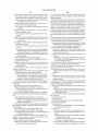
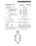
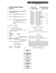
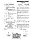
1
USOO8855981B2
(12) United States Patent
(10) Patent N0.:
Oro?no, 11 et a].
(54)
(45) Date of Patent:
TOOLS FOR SYSTEM-LEVEL DESIGN
ENVIRONMENTS
6,226,787 B1 *
6,282,699 B1*
6,330,356 B1
(75)
Inventors: Donald Paul Oro?no, II, .Sudbury, MA
(US); Ramamllrthy Mam, Needham,
’
3/2004 Kodosky et a1. ............ .. 717/125
6,971,065
B2*
6,988,262 B1
(Us)
Notice:
6,715,139 B1 *
6,839,894 B1 *
(73) Ass1gnee. The MathWorks, Inc., Nat1ck, MA
(*)
1/2002
6,748,583 B2 *
-
Subject to any disclaimer, the term of this
12/2001 Sundareswaran et al.
6/2002 Leask et al‘
6,817,010 B2
’
5/2001 Serra et a1. .................. .. 717/125
8/2001 Zhang et a1. ................ .. 717/109
6,412,106 B1 *
(Us) John Ciol? Wellesley MA (Us)
_
*Oct. 7, 2014
6,335,741 B1*
MA (US); Howard Taitel, Sudbury, MA
’
-
US 8,855,981 B2
Nock .......................... .. 715/764
6/2004 Aizenbud-Reshef et a1. 7 17/ 127
11/2004 Aizenbud-Reshefet a1.
1/2005
11/2005
Joshi et al. .................. .. 717/130
Austin
........................ .. 715/763
100% Mallory et al‘
7,051,322 B2 *
5/2006
7,058,950 B2
6/2006 Jeyaraman
7,062,779 B1 *
6/2006 Courtney et al. ........... .. 725/142
patent is extended or adjusted under 35
Rioux ......................... .. 717/143
JBQITIIGS
5
U30 1540’) by 732 days'
N
a
l
7,076,740 B2*
This patent is subject to a terminal dis-
emaZ e
ml
.
7/2006 Santorietal. ............... .. 715/771
(Continued)
c1a1mer.
FOREIGN PATENT DOCUMENTS
(21) Appl.No.: 11/011,298
WO
(
22
)
(65)
El d:
1e
D
WO-99/09473 A1
OTHER PUBLICATIONS
Pnor PUbhcatlon Data
US 2006/0129371 A1
Jun, 15, 2006
RedHaWk NightStar Tools, Version 1.1 Release Notes, Sep. 2002.*
LabVIEW User Manual, 1996 National Instruments Cooperation.*
IntI (:1I
(Continued)
G06G 7/48
2006.01
G06F 3/00
(52)
58
()
2/1999
. 13 2004
ec
’
E2006 01;
Primary Examiner * Kamini S Shah
G06F 9/44
ASSiSleI’lZ Examiner i Kibrom Gebresilassie
U_s_ CL
CPC
G06F 8/34 (2013.01); G06F 3/00 (2013.01)
(74) Attorney, Agent, or Firm * Harrity & Harrity, LLP
USPC ................................ .. 703/6; 703/22; 719/328
(57)
Field of Classi?cation Search
Remote
None
See application ?le for complete search history,
synchronously interacting With graphical models. The remote
auxiliary tools are non-intrusively connected to the graphical
model Without requiring the addition of components to the
References Cited
model de?nition. The remote auxiliary tool can operate in an
observer mode, a bypass mode, and/or a generator mode. In
(56)
US. PATENT DOCUMENTS
5,061,245 A
ABSTRACT
aux1'l'ry
1a too l s are p roV1'ddf
e or non-1ntrus1ve
'
'ly and
these modes, the remote auxiliary tool can synchronously
read, modify, and/or generate data, respectively, in response
10/1991 Waldvogel
5,331,111 A *
7/1994
5,946,485 A
8/1999 Weeren et al.
6,064,409 A *
5/2000
to events Within the executing block diagram.
O’Connell .................... .. 84/602
60 Claims, 12 Drawing Sheets
Thomsen et a1. ........... .. 715/700
Attach Remote Auxiliery
Tool to the Grahical Model
Stert Model Execution
Is the remote
auxiliary tool an observer tool
a bypass tool or a generator
tool'i
541
55
It the remote auxrliary
tool is an observer tool,
read data from the model
and display data
55
I
lithe remote auxiliary
tool is e generator
ll the remote euxiliery tool is
a bypass tool, read data and
ietum modified date to the
model
Stop Execution of the Model,
it Desired
m'» PmVldB dam l°
the model
US 8,855,981 B2
Page 2
(56)
References Cited
U.S. PATENT DOCUMENTS
7,134,090 B2 *
7,171,653 B2
11/2006 Kodosky et al. ............ .. 715/769
1/2007 Albrecht
2004/0205726 A1
10/2004 Chedgey et al.
2004/0210426 A1
10/2004 Wood
2004/0210798 A1*
10/2004 Higashi ......................... .. 714/27
2004/0255269 A1*
12/2004
2005/0144587 A1
2005/0183098 A1*
Santori et al. ............... .. 717/109
6/2005 Bryant
8/2005 Ilic et al. ..................... .. 719/328
7 185 315 B2 >8
2/2007
Sharp et al‘ “““““““““ H 717/109
2006/0041859 A1*
2/2006 Vrancic et al. ..
732003838 B2 >8
7,210,105 B2
4/2007 Kodosky et al‘ “““““““ H 717/116
4/2007 Melamed et al‘
2006/0053211 A1*
2006/0064670 A1*
3/2006 Kornerup et al.
709/217
3/2006 Linebarger et al. ......... .. 717/106
7,210,117 B2 *
4/2007 Kudukoli 61 a1. ........... .. 717/100
2006/0111074 A1
7,215,270 B1
7,302,675 B2
7,302,676 B2
5/2007 Kozak et al‘
11/2007 Rogers et a1,
11/2007 Schmitt et al‘
2006/0129371 A1
2006/0184410 A1
2006/0259870 A1
717/105
5/2006 Petllll er 91
6/2006 Oro?no et al.
8/2006 Ramamurthy et al.
11/2006 Hewitt et al.
7,315,791 B2 *
1/2008 1110 61 al. ..................... .. 702/125
2007/0143455 A1
7,325,210 B2
1/2008 Rao et al‘
2008/0007332 A1
1/2008 Dubowsky
Zoos/0028196 A1
2008/0098349 A1*
1/2008 Kallas
4/2008 Lin et al. ..................... .. 717/106
7,340,747 B1 *
7,439,891 B2
3/2008 Zeliger et al. ............... .. 719/328
10/2008 Kozak et al‘
6/2007 Gorman er 91
7,480,906 B2 *
1/2009 Joffrain 61 a1. .............. .. 717/171
Zoos/0222620 A1
9/2008 thtle 9t al~
7,490,029 B2
7,512,931 B2
2/2009 Wasynczuk et a1,
3/2009 Schmit
2009/0012757 A1
2009/0132993 A1
1/2009 Oro?no et al.
5/2009 Mani et al.
7/2009 Shah 61 al. .................. .. 709/221
2009/0216546 A1
8/2009 Huang et al~
2010/0223564 A1
9/2010 Hsu et al.
7,568,017 B2 *
7,813,825 B2
10/2010 Dubowsky
7 827 068 B2 >8
11/2010 Shah et al‘ “““““““““ H 705/261
2011/0023019 A1
1/2011
738353895 B1
11/2010 Oro?no et 31‘
2011/0214044 A1
9/2011 Davis et a1.
2012/0066762 A1
2012/0089987 A1*
3/2012
4/2012
2013/0198527 A1
2014/0053090 A1
8/2013 Lu et al.
2/2014 Lu et al.
7,904,876 B1 >8
7,966,562 B1 >8
3/2011
6/2011
CritZ ““““““““““““““““ H 717/104
Brewton et al‘ “““““““ H 715/705
7,996,513 B2
8,046,708 B1
8/2011 Gorman et al‘
10/2011 Aldrich
8,336,030 B1 *
12/2012 Boissy ........................ .. 717/126
8,423,326 B1
2002/0049934 A1
4/2013 Astol? et al‘
4/2002 Anderson et al.
2002/0052725 A1 *
5/2002 Wasynczuk et al. .......... .. 703/22
*
et al
345/764
Aniszczyk et al.
Todorovic
Hulick, Jr. .................. .. 719/312
2014/0059525 A1
2/2014 law 81 al~
2014/0059573 A1
2/2014 Jawa et al.
OTHER PUBLICATIONS
International Search Report for PCT/US2005/045493, datedApr. 25,
2002/0143857 A1
2003/0005180 A1
10/2002 Bidarahalli et a1.
1/2003 Schmit et al,
2007
Summons to Attend Oral Proceedings for Application No. 05854256.
2003/0016206 A1
2003/0037322 A1
1/2003 Taitel
2/2003 Kodosky et al.
4, 14 pages, dated Nov. 28, 2012.
Concurrent Computer Corporation, “NightSim User’s Guide,” 136
2003/0046663 A1*
3/2003 Rogers et al. ............... .. 717/125
pages, (2002),
2003/0084127 A1:
500% Bu‘?llfalaet al~ ~
Concurrent Computer Corporation, “RedHaWk Linux, Real-Time
2003;0093239 Al
5;2003 $811113“ """""""""""" " 702/127
2003 0107595 Al
2003/0200076 A1*
~ 709/220
6 2003 C10
10/2003 Kodosky et al.
Lamahha 61 a1.
Software Environment,” 2 pages (2002).
Mansor, Wahidah et al., “Software Methodology for Remote Moni
703/22
........... .. 717/125
t
.
“111% an
dc
ls
0m"
,,P
ystem’
.
l 3509 511
2/2004
2004/0032429 A1
2004/0034696 A1 >8
2/2004 Shah et al.
2/2004 Joffrain et 31‘ “““““““ n 709/217
(2090)
“
”
Natlonal Instruments, LabVIEW, User Manual, 514 pages, (1998).
2004/0045009 A1 >8
3/2004 Bryant
, 719/316
The MathWorks, “Simulink, Model-Based and System-Based
2004/0064750 A1 *
4/2004 Conway ,,,, ,,
, 713/401
Design,” Using Simulink, Version 5, 476 pages (2002).
2004/0093197 A1*
5/2004
2004/0153997 A1
8/2004 Anderson et al.
BillemaZ et al. .............. .. 703/13
* cited by examiner
r°°eemgs °
fTENCON
2004/0031019 A1 *
8V0 '
'
'
US. Patent
0a. 7, 2014
Sheet 1 0f 12
US 8,855,981 B2
CPU
Display Device
m
M
Keyboard
?
Mouse
w
Electronic Device
M
Primary Storage '
Secondary Storage
m
?
Network Interface
m
Modeling/Simulation Application (Simulink®)
5_16
Fig. 1
US. Patent
Oct. 7, 2014
US 8,855,981 B2
Sheet 2 0f 12
2
=
a
@502
2
I>>OE::0moto o
2
2
a
I\c ?gaaw:5.a6%8s2:9Q.3“2 5%
é
m
n6<_x.595N?
@5mi“5w223“a95Es.2“5
5:.625»
2m
5%
W
w2> 85>
wEmz5m._2s<t.5:‘2=
ES29%a3320%n
m
M
E
8>2
OF8E3930N2tE6h;
E
ME
$208516 ;
US. Patent
0a. 7, 2014
Sheet 3 0f 12
US 8,855,981 B2
[-— 103
StateFlow (chart) SFcontrollController *
EEI
file _E_dit §imulatiun mew Iools Add ?elp
Hi
en:speed = 2;
IE
[temp <
off_switch
on_switch
[£1
V
Lo
Off
en:speed = 0;
V
4
F
| >
| Ready
I
Fig. ZB
US. Patent
0a. 7, 2014
Sheet 4 0f 12
US 8,855,981 B2
Attach Remote Auxiliary I50
Tool to the Graphical Model
l
Start Model Execution
l
g'"aerial;'haaaauxiiaiylr60’
Is the remote
auxiliary tool an observer tool
a bypass tool or a generator
54
1
v
If the remote auxiliary
8
56
V
5
I
1
If the remote auxiliary
tool is a generator
ml is an Observer tOOI’
If the remote auxiliary tool is
tOOI’ prOVide data to
read data from the mOdel
a bypass tool, read data and
the mOdel
and display data
return modified data to the
model
___________________
Remove Remote Auxiliary i
60
Tool from Graphical Model
___________________
Stop Execution of the Model, I 62
if Desired
Fig. 3
US. Patent
0a. 7, 2014
Sheet 5 0f 12
US 8,855,981 B2
dsplpc1lCoeffs
HE]
Eile Edit yiew Window ?elp
,2 [HH \
4241226 - ?lmwm 21:5
5
3|
Running
|
||N:12U:1H:100
M51
'
|
Flg. 4A
14
.
K dsplpc1lCoeffs
BE]
?le, Edit yjew Window ?elp
Fig. 4B
16
US. Patent
Oct. 7, 2014
H b E “M Vm men mb W
File Edii \flew Window Help
File Axes Channels Window Help
H e b.
Sheet 6 0f 12
US 8,855,981 B2
US. Patent
Oct. 7, 2014
Sheet 7 0f 12
4
/
..
....
....
-v_k
.
___--o-=
...
“a
2m5329%E2B5;0
muisam2;2%2mmE.lo8;_leo\m.AQ(?g
\1-QmSIE E W
. C~=-3.Eoe%Bm..._@
:EBm.2?2um_M:
E$428625
w.cOZmuEP-
5s:32m8a2Q»:5i03m85
5m-.2
9285
[email protected] ; _ "8W
E...583o68v9u8m
mE328% m8<
US 8,855,981 B2
US. Patent
0a. 7, 2014
Sheet 8 of 12
Provide
US 8,855,981 B2
I80
Graphical Model
V
Place Virtual Auxiliary I82
Tool In Graphical Model
ls Virtual
Auxiliary Tool For
Observation
v
84
86
or Sink?
If Virtual
.
1 Auxiliary Tool ls
I
Augil‘lgmgol I
An Observation
Tool, Observe/
Collect Data
'8 A Sink T00|
’
Collect Data
V
V
If So
If so
con?gured,
Con?gured,
Modify And
If vSo
IfvSo
Register Data
Collected
88
,
I
90
92
Return Data
Collected
1 Con?gured,
Con?gured, I
Initiate An
Initiate An
Action Separate
Action In The
From The Model
Model
Repeat As Necessary
to Debug
Fig. 7
I 96
94
US. Patent
0a. 7, 2014
190
1 02
............................. ..
a
K
4
.
-
1
a
Sheet 9 0f 12
US 8,855,981 B2
US. Patent
Oct. 7, 2014
Sheet 11 0f 12
US 8,855,981 B2
142
148
140
146
law a an" ammo lmssimxn
'
i J. a I;
wast wimhqs
air: r
\ viii-"2 timisxgr
144
FIG. 10
US. Patent
152
=
0a. 7, 2014
Sheet 12 0f 12
1 5O
US 8,855,981 B2
160
-
19.19.9190
set
speedi.
oi
p
h
IE png
-
Engine S?EEd' N w
................ ..161
4 ......................... ..
Engine
FIG. 11
US 8,855,981 B2
1
2
TOOLS FOR SYSTEM-LEVEL DESIGN
ENVIRONMENTS
signal-processing system that ?lters a signal would maintain
a set of previous inputs as the state. The system parameters are
the numerical representation of the static (unchanging) con
?guration of the system and may be viewed as constant coef
?cients in the system’ s equations. For the pendulum example,
a parameter is the length of pendulum and for the ?lter
example; a parameter is the values of the ?lter taps.
FIELD OF THE INVENTION
The present invention relates to a system and method suit
able for non-intrusively observing, modifying, and/ or gener
ating data synchronous with events in an executing block
diagram or graphical model.
Generally, graphical analysis and modeling methods, such
as the block diagram method, are used in modeling for design,
analysis, and synthesis of engineered systems. The visual
BACKGROUND OF THE INVENTION
representation allows for a convenient interpretation of model
components and structure and provides a quick intuitive
notion of system behavior.
During the course of modeling and simulation, it is often
desirable to be able to observe particular data values at certain
Historically, engineers and scientists have utilized graphi
cal models in numerous scienti?c areas such as Feedback
Control Theory and Signal Processing to study, design,
debug, and re?ne dynamic systems. Dynamic systems, which
are characterized by the fact that their behaviors change over
locations of the model, or to observe how data is transformed
time, are representative of many real-world systems. Graphi
cal modeling has become particularly attractive over the last
through the model. Examples of such data values include
signal values, states, work areas, and parameters. Signal dis
plays used in conjunction with a system-level design environ
ment, such as Simulink®, often require multiple display
mechanisms to be associated simultaneously with multiple
few years with the advent of software packages, such as
20
Simulink®, made by The MathWorks, Inc. of Natick Mass.,
LabVlEW®, made by National Instruments Corporation of
Austin, Tex., and the like. Simulink® provides sophisticated
signals to monitor the progress of a model at various points of
software platforms with a rich suite of support tools that
makes the analysis and design of dynamic systems ef?cient,
interest. Currently, block diagram environments offer
25
“scope” blocks to be used in such situations, with each scope
connected to a signal of interest in the model. Alternatively,
environments such as Real-Time Workshop® (manufactured
by The MathWorks, Inc. of Natick Mass.) offer interfaces to
30
non-intrusively observe the data values.
However, conventional non-intrusive approaches to
methodical, and cost-effective.
A dynamic system (either natural or man-made) is a system
whose response at any given time is a function of its input
stimuli, its current state, and the current time. Such systems
range from simple to highly complex systems. Physical
various data values of the model, such that an individual can
dynamic systems include a falling body, the rotation of the
earth, bio-mechanical systems (muscles, joints, etc.), bio
chemical systems (gene expression, protein pathways),
weather and climate pattern systems, etc. Examples of man
made or engineered dynamic systems include: a bouncing
35
observing the various data elements do not allow users to
observe the data synchronously with the various execution
events in the block-diagram or other operating model. Such
synchrony is critical in many scenarios because data values
ball, a spring with a mass tied on an end, automobiles, air
may be not be in a deterministic observable state at all times
planes, control systems in major appliances, communication
during model execution. An example of such a scenario is
when a signal memory location is reused by multiple blocks
networks, audio signal processing, nuclear reactors, a stock
market, etc.
Professionals from diverse areas such as engineering, sci
ence, education, and economics build mathematical models
of dynamic systems in order to better understand system
behavior as it changes with the progression of time. The
mathematical models aid in building “better” systems, where
“better” may be de?ned in terms of a variety of performance
measures such as quality, time-to-market, cost, speed, size,
power consumption, robustness, etc. The mathematical mod
for ef?ciency reasons. Furthermore, allowing synchronous
40
observation of the data also ensures that observers of the data
45
are operating optimally, for example when the data values are
refreshed.
During the course of modeling, it is also often desirable to
bypass or generate data values to aid in re?ning or debugging
a design. For example, one could generate various inputs at a
particular point in the block-diagram model based on various
test scenarios. In another example, one could bypass the
signal values written by a block to remove the transformation
performed by a block during a debugging task. In conven
50
tional applications, such as Simulink®, one needs to intru
els also aid in analyzing, debugging and repairing existing
systems (be it the human body or the anti-lock braking system
in a car). The models may also serve an educational purpose
of educating others on the basic principles governing physical
sively insert blocks and/or lines into the graphical model to
achieve bypass or signal generation. It should be noted that
systems. The models and results are often used as a scienti?c
communication medium between humans. The term “model
based design” is used to refer to the use of graphical models
in the development, analysis, and validation of dynamic sys
these intrusive means of bypass or generation result in the
operations being synchronous with the execution of the
55
block-diagram. However, conventional graphical modeling
tems.
design environments do not offer mechanisms for non-intru
Dynamic systems are typically modeled in model environ
ments as sets of differential, difference, and/or algebraic
equations. At any given instant of time, these equations may
be viewed as relationships between the system’s output
sive, yet synchronous bypass or generation of data values.
SUMMARY OF THE INVENTION
60
response (“outputs”), the system’s input stimuli (“inputs”) at
There is a need in the art for a design tool that interacts with
an executing model in a manner that is non-intrusive, but also
synchronized with the model as the model executes. The
interaction can be decoupled from the model as a remote
that time, the current state of the system, the system param
eters, and time. The state of the system may be thought of as
a numerical representation of the dynamically changing con
?guration of the system. For instance, in a physical system
65
auxiliary tool, which can observe, modify, and/or generate
modeling a simple pendulum, the state may be viewed as the
data from or for the model as it executes. The present inven
current position and velocity of the pendulum. Similarly, a
tion is directed toward further solutions that address this need.
US 8,855,981 B2
4
3
In accordance with various aspects of the present inven
tiate an action upon occurrence of a predetermined execution
tion, the at least one remote auxiliary tool can be an observa
event of the model. The observation tool can non-intrusively
register interest in the at least one of data and an event of the
model upon occurrence of a condition. The observation tool
tion tool. The observation tool can non-intrusively collect
data after attachment to the model. The observation tool can
non-intrusively register interest in at least one of data and an
execution event of the model. The observation tool can ini
can access at least one of data and an event of the model using
one of block diagram primitives and textual language primi
tiate an action upon occurrence of a predetermined execution
tives. The observation tool can choose to block or prevent
event of the model. The observation tool can non-intrusively
register interest in the at least one of data and an event of the
model upon occurrence of a condition. The observation tool
block-diagram execution during the process of observing the
data. The observation tool can choose to allow block-diagram
execution during the process of observing the data.
In accordance with further aspects of the present invention,
can access at least one of data and an event of the model using
one of block diagram primitives and textual language primi
execution during the process of observing the data.
In accordance with further aspects of the present invention,
the at least one remote auxiliary tool can be a bypass tool. The
bypass tool can non-intrusively access and modify at least one
of data and an event of the model. The bypass tool can non
intrusively register interest in at least one of data and an
execution event of the model. The bypass tool can initiate an
action upon occurrence of a predetermined execution event of
the at least one remote auxiliary tool can alternatively be a
the model. The bypass tool can non-intrusively register inter
tives. The observation tool can choose to block or prevent
block-diagram execution during the process of observing the
data. The observation tool can choose to allow block-diagram
bypass tool. The bypass tool can non-intrusively access and
modify at least one of data and an event of the model. The
20
bypass tool can non-intrusively register interest in at least one
of data and an execution event of the model. The bypass tool
an event of the model using one of block diagram primitives
and textual language primitives. The bypass tool can access
can initiate an action upon occurrence of a predetermined
execution event of the model. The bypass tool can non-intru
sively register interest in the at least one of data and an event
of the model upon occurrence of a condition. The bypass tool
est in the at least one of data and an event of the model upon
occurrence of a condition. The bypass tool can additionally
return a modi?ed form of the at least one of data and an event.
The bypass tool can access and modify at least one of data and
25
can additionally return a modi?ed form of the at least one of
data and an event. The bypass tool can access and modify at
least one of data and an event of the model using one of block
and modify at least one of data and an event of the model and
forward a modi?ed form of the at least one of data and an
event to a location distinct from the model.
In accordance with further aspects of the present invention,
bypass tool can access and modify at least one of data and an
the at least one remote auxiliary tool can alternatively be a
generator tool. The generator tool can generate at least one of
data and an event of the model. The generator tool can non
event of the model and forward a modi?ed form of the at least
intrusively register interest in at least one of data and an
one of data and an event to a location distinct from the model.
execution event of the model. The generator tool can initiate
diagram primitives and textual language primitives. The
30
In accordance with further aspects of the present invention,
the at least one remote auxiliary tool can alternatively be a
generator tool. The generator tool can generate at least one of
data and an event of the model. The generator tool can non
intrusively register interest in at least one of data and an
execution event of the model. The generator tool can initiate
an action upon occurrence of a predetermined execution
an action upon occurrence of a predetermined execution
35
event of the model. The generator tool can non-intrusively
register interest in the at least one of data and an event of the
model upon occurrence of a condition. The generator tool can
generate at least one of data and an event of the model using
one of block diagram primitives and textual language primi
event of the model. The generator tool can non-intrusively
register interest in the at least one of data and an event of the
tives.
In accordance with one embodiment of the present inven
tion, a medium is provided for use in a graphical modeling
model upon occurrence of a condition. The generator tool can
environment on an electronic device. The medium holds
40
generate at least one of data and an event of the model using
one of block diagram primitives and textual language primi
45
tives.
instructions executable using the electronic device for per
forming a method of using a remote auxiliary tool. The
method includes connecting at least one remote auxiliary tool
In accordance with further aspects of the present invention,
to the graphical modeling environment prior to execution,
the remote auxiliary tool can be an observation tool, a bypass
tool, and a generator tool. The remote auxiliary tool can be
saved in the model. The remote auxiliary tool can be saved
separate from the model. An identi?er relating to the remote
auxiliary tool can be saved in the model.
In accordance with one embodiment of the present inven
tion, in a graphical modeling environment operating on an
electronic device, a method of using a remote auxiliary tool
during execution, or after execution of a model. The method
continues with operating the at least one remote auxiliary tool
to effect a desired result. The remote auxiliary tool is detach
able from the model during execution of the model in the
50
graphical modeling environment.
In accordance with another embodiment of the present
invention, in a graphical modeling environment, a remote
55
auxiliary tool includes at least one observation tool for non
60
invasively accessing data in a model. The remote auxiliary
tool can be connected to the graphical modeling environment
one of prior to execution, during execution, and after execu
tion of the model. The remote auxiliary tool is detachable
from the model during execution of the model in the graphical
includes connecting it to the graphical modeling environment
prior to execution, during execution, or after execution of a
model. The method continues with operating the at least one
remote auxiliary tool to effect a desired result. The remote
auxiliary tool is detachable from the model during execution
of the model in the graphical modeling environment.
In accordance with further aspects of the present invention,
modeling environment.
the at least one remote auxiliary tool can be an observation
tool. The observation tool can non-intrusively collect data
after attachment to the model. The observation tool can non
intrusively register interest in at least one of data and an
execution event of the model. The observation tool can ini
65
In accordance with another embodiment of the present
invention, in a graphical modeling environment, a remote
auxiliary tool is provided that includes at least one bypass tool
for accessing data in a model. The remote auxiliary tool can
be connected to the graphical modeling environment prior to
execution, during execution, or after execution of the model.
US 8,855,981 B2
5
6
The remote auxiliary tool is detachable from the model dur
environment on an electronic device is provided. The medium
ing execution of the model in the graphical modeling envi
holds instructions executable using the electronic device for
performing a method of using a remote auxiliary tool. The
method includes connecting the at least one generator tool to
ronment.
In accordance with another embodiment of the present
invention, in a graphical modeling environment, a remote
auxiliary tool is provided that includes at least one generator
the graphical modeling environment prior to execution, dur
ing execution, or after execution of a model. The at least one
tool for generating data or events in a model. The remote
generator tool is operated to effect a desired result. The
auxiliary tool can be connected to the graphical modeling
environment prior to execution, during execution, or after
remote auxiliary tool is detachable from the model during
execution of the model in the graphical modeling environ
execution of the model. The remote auxiliary tool is detach
able from then model during execution of the model in the
ment.
In accordance with one example embodiment of the
present invention, the at least one remote auxiliary tool can be
graphical modeling environment.
In accordance with another embodiment of the present
invention, in a graphical modeling environment, a method of
implemented using block diagram primitives. These primi
using a remote auxiliary tool on an electronic device is pro
vided. The method includes connecting at least one observa
tives are aggregated into the block-diagram automatically
prior to execution by the modeling environment.
tion tool to the graphical modeling environment prior to
In accordance with one example embodiment of the
present invention, the at least one remote auxiliary tool can be
execution, during execution, or after execution of a model.
implemented as an event-listener application programming
The at least one observation tool is operated to effect a desired
result. The remote auxiliary tool is detachable from the model
20
during execution of the model in the graphical modeling
environment.
In accordance with another example embodiment of the
using one of block diagram primitives and textual language
primitives.
present invention, in a graphical modeling environment, a
method of using a remote auxiliary tool on an electronic
25
device is provided. The method includes connecting the at
least one bypass tool to the graphical modeling environment
prior to execution, during execution, or after execution of a
model. The at least one bypass tool can be operated to effect
a desired result. The remote auxiliary tool is detachable from
invoked synchronously with block-diagram execution events.
The callbacks may be implemented using one of block dia
30
modeling environment.
35
device is provided. The method includes connecting the at
least one generator tool to the graphical modeling environ
ment prior to execution, during execution, or after execution
40
modeling environment.
the present invention;
45
FIG. 2B is a screen depiction of an example model that can
make use of the tool and method according to one aspect of
the present invention;
FIG. 3 is a diagrammatic illustration of a method of use of
the tool, in accordance with embodiments of the present
to the graphical modeling environment prior to execution,
invention;
50
one observation tool can be operated to effect a desired result.
The remote auxiliary tool is detachable from the model dur
ing execution of the model in the graphical modeling envi
ronment.
In accordance with another example embodiment of the
present invention, a medium for use in a graphical modeling
environment on an electronic device is provided. The medium
holds instructions executable using the electronic device for
performing a method of using a remote auxiliary tool. The
method includes connecting the at least one bypass tool to the
an embodiment of the present invention;
FIG. 2A is a screen depiction of an example model that can
make use of the tool and method according to one aspect of
from the model during execution of the model in the graphical
during execution, or after execution of a model. The at least
The present invention will become better understood with
reference to the following description and accompanying
drawings, wherein:
FIG. 1 is a is a diagrammatic illustration of an electronic
device that can be utilized to execute a method performed in
of a model. The at least one generator tool can be operated to
In accordance with another example embodiment of the
present invention, a medium for use in a graphical modeling
environment on an electronic device is provided. The medium
holds instructions executable using the electronic device for
performing a method of using a remote auxiliary tool. The
method includes connecting the at least one observation tool
gram primitives and textual language primitives.
BRIEF DESCRIPTION OF THE DRAWINGS
In accordance with another example embodiment of the
present invention, in a graphical modeling environment, a
effect a desired result. The remote auxiliary tool is detachable
In accordance with one example embodiment of the
present invention, the at least one remote auxiliary tool can be
implemented as a set of callbacks. These callbacks are
the model during execution of the model in the graphical
method of using a remote auxiliary tool on an electronic
interface (API). This API can provide a non-intrusive and
synchronized interface to at least one observer tool, bypass
tool, or a generator tool. The listener may be implemented
55
FIG. 4A is a screen depiction of an example tool, according
to one aspect of the present invention;
FIG. 4B is a screen depiction of the toolbar of the example
tool of FIG. 3A;
FIG. 5 is a screen depiction of multiple tools, according to
one aspect of the present invention;
FIG. 6 is a screen depiction of multiple tools, according to
one aspect of the present invention;
FIG. 7 is a ?owchart illustrating an example method of use
of the tool, in accordance with embodiments of the present
60
graphical modeling environment prior to execution, during
invention;
FIG. 8 is a screen depiction of two generator tools and two
observer (viewer) tools connected to a model;
execution, or after execution of a model. The at least one
bypass tool is operated to effect a desired result. The remote
FIG. 9 is a screen depiction of a signal and scope manager
auxiliary tool is detachable from the model during execution
of the model in the graphical modeling environment.
In accordance with another example embodiment of the
used to manage remote generator and observer (viewer) tools;
present invention, a medium for use in a graphical modeling
65
FIG. 10 is a screen depiction of a signal selector that is used
to connect remote generator and observer (viewer) tools to a
model; and
US 8,855,981 B2
8
7
FIG. 11 is a screen depiction of context sensitive menus
also include a network interface 514 for communicating with
used to connect remote generator and observer (view) tools to
one or more electronic devices external to the electronic
a model.
device 500 depicted. A modem is one form of network inter
face 514 for establishing a connection with an external elec
tronic device or network. The CPU 502 has either internally,
DETAILED DESCRIPTION
or externally, attached thereto one or more of the aforemen
An illustrative embodiment of the present invention relates
tioned components. In addition to applications previously
mentioned, modeling applications, such as Simulink® 516,
to a remote auxiliary tool and corresponding method of use.
The remote auxiliary tool is formed of at least one of an
can be installed and operated on the electronic device 500.
observation tool, a bypass tool, and a generator tool. The
It should be noted that the electronic device 500 is merely
representative of a structure for implementing the present
invention. However, one of ordinary skill in the art will appre
ciate that the present invention is not limited to implementa
tion on only the device 500 as described herein. Other imple
mentations can be utilized, including an implementation
remote auxiliary tool is non-intrusively and synchronously
connected to a graphical modeling environment prior to
execution, during execution, or after execution of a model.
The remote auxiliary tool is detachable from the model dur
ing execution of the model in the graphical modeling envi
ronment.
The remote auxiliary tool is non-intrusive to the graphical
model, such that the remote auxiliary tool is not embedded in
the model in the same way that other elements of the model
are interconnected and embedded. In the case of a graphical
model using blocks and signals, the user does not add blocks
or signals to the model diagram when attaching a remote
20
Turning now to example embodiments of the present
invention, the method and system of the present invention
operate in a block diagram modeling environment, such as
that of Simulink®. The block diagram modeling environment
auxiliary tool in accordance with the present invention to the
model. Rather, the remote auxiliary tool registers interest
with the model, and during execution the model informs the
based partially or entirely in embedded code, where no user
inputs or display devices are necessary. Rather, a processor
can communicate directly with another processor or other
device.
25
remote auxiliary tool of events of which the tool has requested
is otherwise referred to herein as the graphical model. One of
ordinary skill in the art will appreciate that there are a number
to receive noti?cation. The process of sending an event can be
of different graphical modeling and simulation applications
achieved through, but not limited to, an event-listener appli
cation programming interface (API), a callback based inter
that make general use of blocks or other graphical represen
tations to model or simulate conditions, events, designs,
operations, and the like, or to model and control events imple
mented on hardware devices, and the like. Accordingly, the
present invention is intended for use on all such modeling
face, and/or model and remote auxiliary tool aggregation for
30
execution. The remote auxiliary tool can work with execution
modes that include but are not limited to interpretive, accel
erated, or generated code model execution modes.
FIGS. 1 through 11, wherein like parts are designated by
like reference numerals throughout, illustrate example
embodiments of a remote auxiliary tool, and corresponding
method of use, according to the present invention. Although
applications.
The present invention is generally directed to a system and
35
with a graphical model. FIGS. 2A and 2B are screen depic
tions of a graphical model 10 simulating a dynamic process.
the present invention will be described with reference to the
FIG. 2A shows a version of a time-based or event-based block
example embodiments illustrated in the ?gures, it should be
understood that many alternative forms can embody the
present invention. One of ordinary skill in the art will addi
method for interacting non-intrusively, yet synchronously,
40
diagram graphical model 10A, while FIG. 2B shows a version
of a state-based or event-based ?ow diagram graphical model
10B. As referred to herein, graphical model 10 is intended to
tionally appreciate different ways to alter the parameters of
encompass multiple variations of graphical model, including
the embodiments disclosed in a manner still in keeping with
those shown in FIGS. 2A and 2B. Accordingly, graphical
the spirit and scope of the present invention.
FIG. 1 illustrates one example embodiment of an electronic
45
dynamic systems. Graphical model 10A is formed generally
device 500 suitable for practicing the illustrative embodi
ments of the present invention. The electronic device 500 is
representative of a number of different technologies, such as
of a plurality of blocks 11 that pass signals 13 to represent a
personal computers (PCs), laptop computers, workstations,
personal digital assistants (PDAs), Internet appliances, cellu
model 10 as utilized herein includes graphical model 10A and
graphical model 10B, as well as other graphical models of
50
dynamic system. Graphical model 10B is formed of a plural
ity of states 15 that communicate though blocks in the form of
transitions 17. The particular use or purpose of the graphical
lar telephones, and the like. In the illustrated embodiment, the
model 10 can vary to include anything that can be modeled
electronic device 500 includes a central processing unit
using a graphical modeling environment. Thus, the present
(CPU) 502 and a display device 504. The display device 504
enables the electronic device 500 to communicate directly
invention is not limited to the speci?c example embodiments
discussed herein, as understood by one of ordinary skill in the
with a user through a visual display. The electronic device 500
further includes a keyboard 506 and a mouse 508. Other
55 art.
In the example embodiment, time-based graphical models
potential input devices not depicted include a stylus, track
ball, joystick, touch pad, touch screen, and the like. The
electronic device 500 includes a non-transitory computer
readable medium such as primary storage 510 and secondary
storage 512 for storing data and instructions. The storage
10A have blocks connected by signals. Blocks are respon
sible for computing the values of signals as time progresses.
The arrows denote the computational direction of the signal.
60
devices 510 and 512 can include such technologies as a ?oppy
drive, hard drive, tape drive, optical drive, read only memory
(ROM), random access memory (RAM), and the like. Appli
cations such as browsers, JAVA virtual machines, and other
Input ports read signals and output ports write signals. The
user of the present invention may wish to obtain a reading of
a value of one of the signals 13 in the graphical model 10, or
of one of the processes in one of the blocks 11. However, in
the graphical model 10 illustrated, there is no instance of a
65
scope shown with the model. Accordingly, if the graphical
utilities and applications can be resident on one or both of the
model 10 is running a model execution at the time illustrated
storage devices 510 and 512. The electronic device 500 can
in the ?gure, conventional modeling applications in the situ
US 8,855,981 B2
10
ation illustrated have no mechanism for a user to be able to
ence of user-de?nable pre-execution and/or post-execution
take readings of signal or internal block/model states syn
callbacks or events associated with any of the methods of the
chronously.
computational blocks in the graphical model 1 0, such that the
However, with the remote auxiliary tool of the present
invention in accordance with one embodiment, an event
callback or event enforces proper synchronization for data
transfer to and from the tool. Such an API can likewise be
listener API or equivalent tool is provided associating a tool
with the graphical model 10 without being embedded in the
provided where the de?nitions refer to data nodes in a physi
cal hardware device, such as memory locations in a processor,
a physical I/O protocol for a processor or an FPGA or ASIC,
or some other de?ned method for data delivery, as understood
graphical model 10. For example, if the user wishes to know
the value of the signal at pointA in the graphical model 10, the
user implements the remote auxiliary tool of the present
by one of ordinary skill in the art. A unique identi?er can be
provided for each signal in the graphical model 10 or hard
invention to initiate an observation event, or equivalent ob ser
vation tool. The user registers with the model, using the
ware, such that the tool can be associated with any signal or
event-listenerAPI, a request to invoke an ob server when point
group of signals. Methods to read, and optionally write, signal
data via the unique identi?er, which can be synchronized by
the pre-execution and/or post-execution callback or event,
A in the graphical model 10 is computed by the source block
of the signal of point A. As the model is executing, when the
signal at point A is re-computed by the source block of the
can be provided. Furthermore, textual, graphical, audio,
signal, an event is sent to the listener. The listener in this
illustrative example is an observer that reads the value of the
visual, tactile, or other data rendering techniques and capa
bilities supported by, or interfaced to, the modeling environ
signal at point A and displays the value appropriately in a
device, such as a graphical display scope. It should be noted
20
ment can be provided, such that the signal data is presented to
that throughout this description the example embodiments
user in a discemable manner.
make use of an API form of tool to connect the remote aux
The remote auxiliary tool can include different types of
observer tools, such as display scopes, strip chart recorder, an
oscilloscope, a spectrum analyzer, a 2-port network analyzer,
a logic signal display, a waterfall plot, a communications
constellation plot, an audio output device, and a video display
device. The observer tool can also be a non-graphical tool,
iliary tool to the model. However, one of ordinary skill in the
art will appreciate that the remote auxiliary tool does not need
to be implemented in the form of an API, but rather, can be
25
implemented using a number of different tools, including
library based modules, and other tools. As such, references to
an API in the present description are intended to include APIs
as well as such other equivalent tools noted above. In addi
tion, an alternative example embodiment of the present inven
tion makes use of an aggregation programming paradigm to
such as a tool that reads the model data (such as the signal at
30
achieve the non-intrusive and synchronized behavior of the
remote auxiliary tool.
The remote auxiliary tool itself does not need to be repre
sented graphically in the graphical model 10. However,
because the remote auxiliary tool registers listeners with the
35
model, the model can insert a graphical symbol or text, such
area of debugging a simulation, when incorrect values are
seen they can be altered enabling the simulation to continue
as symbol 19, or other representation in the graphical model
10 showing the existence of the listener for the remote aux
iliary tool. Such graphical representation can be, for example,
40
shown in the block 11, similar to those illustrated in FIGS. 2A
and 2B, indicating the remote auxiliary tool is connected to
the internal state of the block 11 and not the signal 13. More
speci?cally, in the illustrative example showing the symbol
19, connections made by the remote auxiliary tool can be
45
described by selection of one or more signals 13 from a list of
all available signals 13 in the graphical model 10. The remote
auxiliary tool can also be described by the direct entry of an
identi?cation of one or more signals 13 in the graphical model
10. The connections can be highlighted at some point in time,
to associate a symbol 19 with one or more selected signals 13.
50
Likewise, a GUI can be provided with a multiple-document
interface type of layout in which a master GUI contains one or
more visual display device windows with additional inter
55
60
are described herein. In addition, FIG. 3 is a diagrammatic
illustration of a method of using the remote auxiliary tool
realized using the event-listener API. In accordance with one
example embodiment of the present invention, a user can
attach a remote auxiliary tool to a model to listen to speci?c
point” symbol (small ‘lollipop’ icon) connected to a signal
dance with an example embodiment of the present invention,
the API that enables the practice of the remote auxiliary tool
in accordance with the present invention, includes the pres
using the event-listener API to non-intrusively and synchro
nously connect the remote auxiliary tool(s) to the model.
In addition, the displays of the remote auxiliary tool, if
required, are provided separate from the graphical model 10,
faces for managing the connections to the model correspond
ing to each remote tool.
Several example embodiments of implementations of the
remote auxiliary tool in accordance with the present invention
For example, this can be accomplished by pressing a button in
line for as long as the virtual connection remains. For con
nections to internal block state as in the illustrative block 11,
the connections can be created in similar fashion to signal
selection, except that a block 11 is selected.
The remote auxiliary tool can be connected to the model 10
using an event-listener API. More speci?cally and in accor
without having to shut down. The remote auxiliary tool can
include different types of generator tools such as, sine wave,
square wave, pulse, or any arbitrary user created functions
that produce data for the model. One of ordinary skill in the art
will appreciate that the present invention is not limited to
thus keeping with the non-intrusive feature of this invention.
the display interface, with the corresponding signal 13 in the
model highlighted by color, blinking, or other temporary or
persistent graphical indication, in addition to textual or other
representations. The connection can also be highlighted by a
graphical affordance in the graphical model 10, such as a “test
point A of the illustrative model 10) and sends the data to
another system for processing. The remote auxiliary tool can
include different bypass tools such as a non-graphical tool
that reads data from the model 10 and, if the data exceeds a
speci?ed limit, the data is set to that limit. The modi?ed data
is then returned to the model. This makes the bypass tool
useful for providing fault tolerant actions when the model is
executing in real-time. Another use of the bypass tool is in the
events before, during, or after model execution (step 50). The
user can detach a remote auxiliary tool before, during, or after
graphical model (10) execution (steps 60 and 60'). Connec
65
tions to the model (10) by the remote auxiliary tool are main
tained while the model is not running. When the model is not
running, the user can edit the model and possibly change it
structure. If the act of editing the model deletes an object such
US 8,855,981 B2
11
12
as a block (11) or line (13) that is connected to a remote
are connections established for each display corresponding to
auxiliary tool, the tool becomes disconnected from the model.
The user can start the model execution (step 52). During
signals originating from multiple graphical models 10. A ?rst
display 20 reports data from a ?rst graphical model. A second
display 22 reports data from a second graphical model. A
third display 24, a fourth display 26, and a ?fth display 28 all
report data from a third graphical model. The remote auxil
model execution model and block methods are invoked. With
in Simulink® this consists of a simulation loop. Each com
putational block in Simulink® consists of multiple run-time
methods that are executed within the simulation loop. Sim
iary tool is formed of the collection of the displays 20, 22, 24,
26, and 28. Each of the displays operates independently and
ulink® decomposes block methods by type and executes
them in a prede?ned manner from model models that are
pulls data from different model locations. The displays can
pull data from the same model location if desired. Further
more, as mentioned previously, each of the collection of the
invoked by the simulation loop. During execution of a model
or block method, if a block with registered listeners is
encountered, the model sends an event causing the respective
listener (steps 54, 56, and 58) of the remote auxiliary tool to
displays 20, 22, 24, 26, and 28 forming the remote auxiliary
tool can be individually or collectively attached or detached
execute. The listener of the remote auxiliary tool can be an
from the graphical models before, during, or after the graphi
observer tool reading and displaying data (step 54), a bypass
tool reading data and returning modi?ed data (step 56), or a
generator tool providing data (step 58). When execution com
pletes, the model returns to the not running state (step 62).
One of ordinary skill in the art will appreciate that, as
mentioned previously, the distinction between observation or
20
observer tool, bypass tool, and generator tool as outlined
above is done merely to convey different aspects of the inven
tion clearly. However, the present invention does not require
remote connection manager 32. The remote connection man
ager 32 provides an organized GUI that enables a user to track
and select different elements making up the remote auxiliary
tool. One of ordinary skill in the art will appreciate that the
that the tool fall completely within one or the other of the
observation or observer tool, bypass tool, or generator tool
categories. Rather, the tool can be a hybrid mixture of the
three forms or varieties of tool. Furthermore, it should be
25
noted that the remote auxiliary tool is formed of at least one
tool, such that the speci?c con?guration of each tool forming
the remote auxiliary tool becomes less relevant to the opera
tion of the remote auxiliary tool, because the same function
30
ality of the remote auxiliary tool can be implemented with
remote auxiliary tool of the present invention is formed of a
combination or mixture of the different variations possible
with the tool operational characteristics, in addition to a com
bination of multiple tools having the same or different opera
tional characteristics.
example remote connection manager 32 is shown as a tree
structure. However, any number of ?le organization tech
niques and con?gurations can be utilized to generate the
remote connection manager 32, such that the manager 32 is
not limited to the speci?c embodiment illustrated.
As described, the remote auxiliary tool includes at least one
tool. The remote auxiliary tool is attached to the model in the
graphical modeling environment prior to execution, during
numerous variations of ob servation, bypass, or generator, and
number of tools forming the remote auxiliary tool. Accord
ingly, the present invention is not limited to the speci?c
example embodiments of tools described herein. Rather, the
cal models are implemented.
FIG. 6 is another screen depiction of an MDI GUI 30 with
a pre-loaded collection of displays forming the remote aux
iliary tool, such as those illustrated in FIG. 5. In addition, the
remote auxiliary tool in this example embodiment includes a
execution, and/ or after execution of a model. The remote
35
40
auxiliary tool is detachable from the model during execution
of the model in the graphical modeling environment.
The illustrative embodiments have been primarily
described with regard to their observation functionality. The
observation tool non-invasively collects data after attachment
to the model 10. The observation tool likewise can non
invasively register interest in data or some event of the graphi
One example implementation of the remote auxiliary tool
cal model 10. The registration of the data or event can be
of the present invention is shown in FIG. 4A and FIG. 4B.
displayed in accordance with the examples illustrated herein.
In addition, the remote auxiliary tool can initiate an action
FIG. 4A is a screen depiction of a tool resulting from a user
implementing the remote auxiliary tool. The remote auxiliary
45
tool is implemented as a waterfall plot 12. The waterfall plot
12 is a visual display of data virtually connected to the graphi
cal model 10 at pointA. The remote auxiliary tool can include
such as a maximum or a minimum, is achieved in a graphical
model as it is running, the remote auxiliary tool can register
a number of different interfacing options, some of which can
be implemented in a toolbar con?guration. For example, FIG.
upon registration of a predetermined characteristic of the data
or event ob served. For example, if a predetermined data point,
50
the occurrence and forward instructions or implement other
actions to address the occurrence. Such actions may include
4B shows a toolbar 14 having a number of standard buttons.
pausing the model execution, forwarding data relating to
One of ordinary skill in the art will recognize several of the
symbols representing the functions of the buttons. One
example button that can be utilized in conjunction with the
present invention is a highlight button 1 6, which when clicked
on will highlight the signal in the graphical model 10 being
displayed by the remote auxiliary tool, such as the waterfall
plot 12. One of ordinary skill in the art will appreciate that a
number of different functions can be implemented in the
remote auxiliary tool of the present invention in accordance
with particular function or operation of the remote auxiliary
tool.
In addition, the remote auxiliary tool interface in a particu
lar embodiment can vary. For example, in FIG. 5, the remote
auxiliary tool is implemented as a multiple document inter
other points in the model at the time of the occurrence, send
ing a message to the user, implementing a change in the
operation of a separate model and/ or hardware device, and the
like.
The implementation of the remote auxiliary tool can be in
the form of a non-blocking tool if its primary purpose is one
face (MDI) style GUI design, incorporating multiple display
devices in a single master window 18. In this example, there
55
60
65
of registration, recordation, or observation. In this mode, the
model that is executing does not wait for the attached remote
auxiliary tool to ?nish responding to a particular execution
event. The remote auxiliary tool can likewise be implemented
in the form of a blocking tool if its purpose is to in?uence
model execution. In this mode, the model to which the remote
auxiliary tool is attached waits until the tool has generated an
action in response to receipt an execution event. Such actions
could include pausing the model execution, or other actions
that affect the model or the execution or operation of the