1
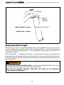
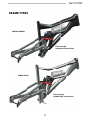
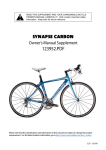
READ THIS SUPPLEMENT AND YOUR CANNONDALE BICYCLE
OWNER’S MANUAL CAREFULLY! Both contain important safety
information. Keep both for future reference.
moto
Owner’s Manual Supplement
122172.PDF
CONTENTS
safety information ................................ 1
About This Supplement........................... 2
Important Composites Message........... 2
Intended Use................................................ 3
Building Up A Frameset............................ 4
Bike Stands.................................................... 4
Extreme Temperatures.............................. 4
Inspection and Crash Damage.............. 5
Repainting and Refinishing.................... 5
Maximum Fork Length............................. 6
Minimum Seat Post Insert....................... 7
Tire Size.......................................................... 8
FRAME TYPES.................................................... 9
SPECIFICATIONS.............................................10
HEAD TUBE.......................................................12
DROPOUTS.......................................................13
SHOCK LINK, PUSH LINK,
MAIN PIVOT.....................................................14
REAR SHOCK....................................................16
MAINTENANCE ..............................................18
Frame Protection......................................19
CABLE ROUTING ...........................................20
WARNING
This supplement may include procedures beyond the scope of general mechanical aptitude. Special
tools, skills, and knowledge may be required. Improper mechanical work increases the risk of an
accident. Any bicycle accident has risk of serious injury, paralysis or death. To minimize risk we strongly
recommend that owners always have mechanical work done by an authorized Cannondale retailer.
Please note that the specifications and information in this manual are subject to change for product
improvement. For the latest product information, go to http://www.cannondale.com/tech_center/
05/08
Important Composites
Message
SAFETY INFORMATION
About This Supplement
Cannondale Owner’s Manual Supplements
provide important model specific safety,
maintenance, and technical information. They
are not replacements for your Cannondale
Bicycle Owner’s Manual.
Your bike is made from composite materials
also known as “carbon fiber.”
All riders must understand a fundamental
reality of composites. Composite materials
constructed of carbon fibers are strong and
light, but when crashed or overloaded, carbon
fibers do not bend, they break.
This supplement may be one of several for
your bike. Be sure to obtain and read all of
them.
For your safety, as you own and use the bike,
you must follow proper service, maintenance,
and inspection of all the composites (frame,
stem, fork, handlebar, seat post, etc.) Ask your
Cannondale Dealer for help.
If you need a manual or supplement, or have a
question about your bike, please contact your
Cannondale Dealer immediately, or call us at
one of the telephone numbers listed on the
back cover of this manual.
We urge you to read PART II, Section D. “Inspect
For Safety” in your Cannondale Bicycle Owner’s
Manual BEFORE you ride.
You can download Adobe Acrobat PDF
versions of any Cannondale Owner’s Manuals
or Supplements from our website: http://www.
cannondale.com/bikes/tech.
WARNING
• This manual is not a comprehensive
safety or service manual for your bike.
YOU CAN BE SEVERELY INJURED,
PARALYZED OR KILLED IN AN ACCIDENT
IF YOU IGNORE THIS MESSAGE.
• This manual does not include assembly
instructions for your bike.
• All Cannondale bikes must be completely
assembled and inspected for proper
operation by a Cannondale Dealer before
delivery to the owner.
122172.PDF
Intended Use
This model bike is intended for Condition 4
(All Mountain) riding. Condition 4 symbol
shown in Figure 2.
NOT INTENDED
For Hardcore Freeriding, Extreme Downhill,
Dirt Jumping, Slopestyle, or very aggressive or
extreme riding .
TRADE OFF
For riding on
rough trails
with medium
obstacles
All-Mountain bikes are more rugged than cross
country bikes, for riding more difficult terrain.
All-Mountain bikes are heavier and harder
to ride uphill than cross country bikes. AllMountain bikes are lighter, more nimble and
easier to ride uphill than Freeride bikes. AllMountain bikes are not as rugged as Freeride
bikes and must not be used for more extreme
riding and terrain.
MAXIMUM WEIGHT LIMIT
Figure 2.
CONDITION 4
Condition 4 bikes are designed for riding
Conditions 1, 2, and 3, plus rough technical
areas, moderately sized obstacles, and small
jumps.
RIDER
lbs / kg
LUGGAGE *
lbs / kg
TOTAL
lbs / kg
300 / 136
5 / 2.3
305 / 138
* Seat Bag Only
WARNING
For trail and uphill riding. All-Mountain bicycles
are: (1) more heavy duty than cross country
bikes, but less heavy duty than Freeride bikes,
(2) lighter and more nimble than Freeride bikes,
(3) heavier and have more suspension travel
than a cross country bike, allowing them
to be ridden in more difficult terrain, over
larger obstacles and moderate jumps, (4)
intermediate in suspension travel and use
components that fit the intermediate intended
use, (5) cover a fairly wide range of intended
use, and within this range are models that are
more or less heavy duty. Talk to your retailer
about your needs and these models.
UNDERSTAND YOUR BIKE AND ITS
INTENDED USE. USING YOUR BIKE THE
WRONG WAY IS DANGEROUS.
Industry usage Conditions 1 - 5 are
generalized and evolving. Consult your
Cannondale Dealer about how you intend
to use your bike.
Please read your Cannondale Bicycle
Owner’s Manual for more information
about Intended Use and Conditions 1-5.
Building Up A Frameset
Protect From
Extreme Temperatures
Before building up a frameset, consult with
your Cannondale Dealer and the component
manufacturers, and discuss your riding style,
ability, weight, and interest in and patience for
maintenance.
• Protect your carbon bike from extreme
temperatures when storing or transporting it.
• Allow your bike to cool off or warm up before
you ride
• Do not store your bike in places where the
temperature will exceed 66.5C° (150°F). For
example, do not leave your bike lying flat in
a black pickup truck bed in the desert sun, or,
under the glass of a hatchback auto.
Make sure the components chosen are
compatible with your bike and intended for
your weight and riding style.
Generally speaking, lighter weight components
have shorter lives. In selecting lightweight
components, you are making a trade-off,
favoring the higher performance that comes
with less weight over longevity. If you choose
more lightweight components, you must
inspect them more frequently. If you are a
heavier rider or have a rough, abusive or “go for
it” riding style, buy heavy duty components.
Read and follow the component manufacturers
warnings and instructions.
Bike Stands
The clamping jaws of an ordinary bike stand
can generate a crushing force strong enough
to seriously damage and ruin your bike frame.
CAUTION
Never place your bike in a bike stand by
clamping the frame. Place your bike in a stand
by extending the seat post and positioning
the stand clamp on the extended seat post.
Don’t extend beyond the MINIMUM INSERT
line marked on the seat post.
Since your carbon seat post can also be
damaged by clamping force, adjust the
stand clamp for the minimum clamping force
needed to secure the bike.
Its a good idea to remove your current seat
post and use an old one when mounting
your bike in a stand.
122172.PDF
Inspection & Crash
Damage of Carbon Frames
WARNING
AFTER A CRASH OR IMPACT:
Inspect frame carefully for damage (See
PART II, Section D. Inspect For Safety in your
Cannondale Bicycle Owner’s Manual.)
Repainting Or Refinishing
You should not paint over the existing finish,
refinish or repaint your bike. The carbon fiber
composites making up the frame are held
together by some extremely strong bonding
chemicals. However, these bonds can be
attacked or weakened by paint stripping or
refinishing chemicals.
WARNING
Do not ride your bike if you see any sign
of damage, such as broken, splintered, or
delaminated carbon fiber.
Repainting, painting over, retouching, or
refinishing your frame or fork can result in
severe damage leading to an accident. You
can be severely injured, paralyzed or killed.
ANY OF THE FOLLOWING MAY INDICATE
A DELAMINATION OR DAMAGE:
Refinishing chemicals : Solvents, and
strippers can attack, weaken, or destroy
the important composite chemical bonds
holding your frame together.
An unusual or strange feel to the frame
Carbon which has a soft feel or altered
shape
Creaking or other unexplained noises,
Using abrasives or sanding the frame/fork
structure, original paint, decals, or coatings
through the use of mechanical actions
such as plastic or glass bead blasting or
other abrasive methods such as sanding
or scraping can remove frame material or
weaken it.
Visible cracks, a white or milky color present
in carbon fiber section
Continuing to ride a damaged frame
increases the chances of frame failure,
with the possibility of injury or death of
the rider.
HEADTUBE
HEADSET
PARTS or
ADAPTERS
MAXIMUM FORK LENGTH
MOTO CARBON = 545mm
MOTO ALLOY = 560mm
AXLE
Maximum Fork Length
Maximum Fork Length is an important frame safety testing specification. You must observe
the measurement when installing headset parts, headset adapters, installing and adjusting
a fork, and selecting replacement forks. In this supplement the number is also listed in the
specifications section.
HOW TO MEASURE: 1. Install headset and fork. 2. Extend fork and measure the distance from
the bottom of the head tube to the center of the wheel axle. Do not measure from the bottom of
headset bearing cups or head tube adapters. The measurement MUST be taken from the bottom
of the head tube!!
WARNING
DO NOT EXCEED MAXIMUM FORK LENGTH Exceeding the MAXIMUM FORK LENGTH limit
can overload the frame causing it to fail (break) while riding.
YOU CAN BE SEVERELY INJURED, PARALYZED OR KILLED IN AN ACCIDENT
IF YOU IGNORE THIS WARNING.
122172.PDF
SEATPOST
ity
t tube.
for clar
the sea wn removed
f
o
p
o
T
der sho
Seat bin
100mm
SEATTUBE
Minimum Seat Post Insert Depth (MOTO CARBON)
For MOTO carbon frames, the seat post must be inserted a minimum of 100mm or 4 inches
WARNING
MAKE SURE AT LEAST 100 mm OF THE SEAT POST IS INSERTED INTO THE FRAME AT ALL
TIMES. Failure to insert the seat post at least 100 mm can place a very high stress on the seat
tube top tube junction causing the frame to fail while riding.
Remove the seat post. Measure 100 mm from the bottom of the seat post. Use a permanent
marker to mark the post at 100 mm. When adjusting the seat post height in the seat tube,
never adjust the seat post so that the line you mark is above the top edge of the seat tube.
YOU MUST ALSO BE AWARE THAT bicycle seat posts are permanently marked by the
manufacturer with a “MINIMUM INSERT” line on the seat post itself. You must not rely on this
marking as an indication of the proper MINIMUM SEAT POST INSERTION DEPTH.
YOU CAN BE SEVERELY INJURED, PARALYZED OR KILLED IN AN ACCIDENT
IF YOU IGNORE THIS WARNING.
Tire Size
WARNING
OBSERVE THE “MAXIMUM TIRE WIDTH” FOR YOUR BIKE FOUND IN THE SPECIFICATIONS
PAGE OF THIS MANUAL.
Mounting the wrong size tires can result in the tires hitting the fork or frame when riding. If
this happens, you can lose control of your bike and you can be thrown off, a moving tire can
be stopped because it touches the fork or frame.
Do not mount oversized tires, ones that rub or hit the fork or frame, ones that result in too
little clearance, or ones that can hit the fork or frame when the suspension is fully compressed
or when riding.
Take care that the tires you select are compatible with your bike’s fork or frame design. Also,
be sure to follow the manufacturer’s recommendations of your front fork and rear shocks.
When you are considering tires for your bike consider...
The actual measured size of a tire may be different than its sidewall marking. Each time you
mount a new tire, take the time to inspect the actual clearance between the rotating tire
and all parts of the frame. The U.S. Consumer Product Safety Commission (CPSC) requires at
least 1/16” (1.6 mm) tire clearance from any part of the bike. Allowing for lateral rim flex and a
wheel or rim that is out-of-true will likely mean choosing a rear tire that provides even more
clearance than the CPSC recommends.
ASK YOUR CANNONDALE DEALER FOR THE RIGHT TIRES FOR YOUR BIKE AND ITS
PARTICULAR COMPONENTS!
YOU CAN BE SEVERELY INJURED, PARALYZED OR KILLED IN AN ACCIDENT
IF YOU IGNORE THIS WARNING.
122172.PDF
FRAME TYPES
MOTO CARBON
Front triangle
composite construction
MOTO ALLOY
Front triangle
welded-alloy construction
ICSG
MOTO SPECIFICATIONS
FRAME
BB SHELL WIDTH
MAX. FORK LENGTH
See page 6.
MINIMUM SEAT POST INSERT
See page 7
INTENDED USE
See page 3.
MAX. TIRE WIDTH
SEAT POST DIA.
FRONT DERAILLEUR DIA.
CHAINLINE
DROPOUT SPACING
REAR HUB SPACING
REAR HUB AXLE
REAR BRAKE MOUNT
LEVERAGE RATIO
GEOMETRY (cm/ in)
SEAT TUBE LENGTH
SEAT TUBE ANGLE
TOP TUBE HORIZONTAL
TOP TUBE ACTUAL
STAND OVER
HEAD TUBE ANGLE
HEADTUBE LENGTH CARBON
HEADTUBE LENGTH ALLOY
WHEEL BASE
FRONT CENTER DISTANCE
CHAINSTAY LENGTH
BOTTOM BRACKET DROP
BOTTOM BRACKET HEIGHT
FORK RAKE
FORK TRAIL
REAR TRAVEL
REAR SHOCK
STROKE
2.25 in, 57 mm
EYE-TO EYE 7.875 in, 200 mm
73 mm,
CARBON - 545 mm
ALLOY - 560 mm
CARBON - 100 mm, 4 in.
ALLOY - See seat post.
BUSHING WIDTH
CONDITION 4
26 x 2.4 in
34.9 mm
34.9 mm
50 mm
135 mm
135 mm
MAXLE, QR
INTERNATIONAL
STANDARD
2.6-3.0:1
SMALL
41.0/16.1
72.5˚
57.8/22.8
53.5/21.1
74.8/29.4
67.5˚
13.6/5.3
11.4/4.5
109.8/43.2
68.0/26.8
42.0/16.5
3.3/1.3
36.3/14.3
4.5/1.8
8.8/3.5
16.0/6.3
TIGHTENING TORQUES
Main Pivot Nut
Shock Link Pivot Nut
Shock Mounting Bolts
Push Link Pivot Bolts
Dropout Mounting Bolts
Seat Binder
BOLT HOLE DIA.
10
LOWER:
37.4 ± 0.05 mm
8. ± 0.05 mm
SAG - 20 - 25%
Adjust air pressure to achieve
11.5 - 14.3 mm of sag. See page 17.
MEDIUM
42.9/16.9
*
60.3/23.7
56.0/22.0
76.4/30.1
*
13.6/5.3
11.4/4.5
112.4/44.3
70.6/27.8
*
*
*
*
*
*
N•m
16
9
12
11
5
6.8
UPPER:
32.4 ± 0.05 mm
In•Lbs
142
80
106
98
44
60
LARGE
48.2/19.0
*
62.9/24.8
59.0/23.2
80.7/31.8
*
16.1/6.3
14.0/5.5
115.6/45.5
73.8/29.1
*
*
*
*
*
*
Loctite™
242
242
242
242
242
X-LARGE
53.7/21.1
*
65.2/25.7
62.5/24.6
82.0/32.3
*
16.1/6.3
14.0/5.5
118.4/46.6
76.6/30.2
*
*
*
*
*
*
Page
14
14
14
14
13
11
122172.PDF
1
SEAT BINDER
100mm
MINIMUM SEAT POST INSERT
(MOTO CARBON)
TOP TUBE
2
HEADTUBE
LENGTH
HEAD TUBE
SEAT TUBE
Water bottle cage mount
L and XL sizes only
SHOCK LINK
SHOCK LINK PIVOT
PUSH LINK
SWINGARM
AY
ST
AT
E
S
7
4
TAY
CHAINS
DOWNTUBE
3
DOWNTUBE PROTECTOR
(MOTO CARBON)
MAIN PIVOT
NOTE: Here on both the drive and non-drive
side chainstays, you may notice a slight
dimple in the surface of the chainstay. The
dimple is part of design swingarm which
locates a bend radius on the reverse side of
the chainstay.
NO.
1
ORDER
DESCRIPTION
QC842/BBQ
SEATBINDER,MTN,34.9,BLK
QC843/BBQ
SEATBINDER,MTN QR,34.9,BLK
2
KP002/
BADGE,HEADSHOK
3
KP054/
SCUFFGUARD,DOWNTUBE
4
KF102/
GROMMET,-10 PCS
5
KF363/
CABLEGUIDE (MOTO CARBON)
6
KF085/
CABLEGUIDE (MOTO ALLOY)
7
KF086/
HYDRAUL. BRK GUIDES,10 PCS
8
KF014/
CABLESTOP, INSERTS - 2 PCS
11
5
6
8
HEAD TUBE
MOTO ALLOY
MOTO CARBON
Top Cap
Compression Ring
Bearing
8H x 52 x Ø40 x 45° x 45°
Upper Bonded Cup
KP002/
One.Point.Five
compatible
KP081/
only
KP002/
Lower Bonded Cup
Bearing
8H x 52 x Ø40 x 45° x 45°
Crown Race
MOTO CARBON frames feature permanently bonded headset bearing cups (above left). The
cups accept only the Cannondale headset bearing in the kit shown above. The headset kit is
compatible with 1.5” steerers.
MOTO ALLOY frames are compatible the One.Point.Five standard and One.Point.Five to 1 1/8”
conversion headsets.
CAUTIONS
1. Do not face, surface, or cut the head tube or bearing cups for any reason.
2. Please note that when removing bearings from bonded cups, extra care must be used so
that the tool used to drive out the bearing is NOT located on any part of the bonded cup.
12
122172.PDF
DROPOUTS
GROMMET
KF102/
12mm MAXLE DROPOUTS
KP079/
Loctite 242 (blue)
13 Nm
115 In Lbs
THRU AXLE 135mm MAXLE
KP080/
NOTE: Follow ROCKSHOX MAXLE
instructions for wheel installation.
Loctite 242 (blue)
13 Nm
115 In Lbs
135mm STANDARD QR DROPOUTS
KP078/
Both dropout kits include mounting hardware (chainring bolts)
13
SHOCK LINK , PUSH LINK, MAIN PIVOT
3
23
24
2
1
10
24
7
6
8
5
4
11 Nm
98 In Lbs
9 Nm
80 In Lbs
10
8
24
11 Nm
98 In Lbs
23
24
12
19
16 Nm
142 In Lbs
20
18
22
NON-DRIVE SIDE
DRIVE SIDE
NOTES:
1. Apply grease to items 4, 12
2. Apply Loctite 242 to items 6, 8, 10, 22
3. Items 10, 19, 20 ridged side (a) face bearing, smooth side (b) face out.
4. Item23,theshockbushings, areavailableonlythroughtherearshockmanufacturer.
14
122172.PDF
2
1
SHOCK LINK ASSEMBLY
14
4
5
15
6
(b)
(a)
SHOCK BOLTS
24
PUSH LINK ASSEMBLY
16
8
7
17
11
3
7
10
MAIN PIVOT ASSEMBLY
12
21
20
19
18
(a)
NO. (QTY)
(b)
(b)
(a)
(b)
22
(b)
ORDER
DESCRIPTION
NO. (QTY)
ORDER
DESCRIPTION
KP082/
SHOCK,FOX,DHXAIR5.0MOTO
3, 7(2), 8(4),
10(4), 16(4),
17(4)
KP087/
LINK,PUSH,BLK ASS’Y
KP088/
LINK,PUSH,HWARE
KP089/
LINK,SHOCK,CARBONASS’Y
KP090/
LINK,SHOCK,ALLOY ASS’Y
KP091/
LINK,SHOCK,HWARE
24
KP083/
SHOCKMOUNTHWARE,MOTO
12, 19, 20, 22
KP084/
PIVOT SWINGARM, MOTO
18, 21
KP085/
BEARINGS, MAIN, MOTO
1, 2, 4, 6, 11(2),
5(2),14(2),15(2)
3, 7(2), 8(4),
10(4), 16(4),
17(4)
KP086/
LINK,PUSH,RED ASS’Y
4,6,11(2),13(2),
14(2), 15(2)
15
REAR SHOCK
UPPER
SHOCK LINK
PIVOT
LOWER
SHOCK MOUNTING NOTE:
The MAIN PIVOT and the SHOCK LINK PIVOT
nuts should be loosened before the UPPER
and LOWER rear shock mounting bolts are
tightened . This will allow the parts to be
drawn together properly. Once the shock
is mounted and the bolts tightened to the
final torque. Tighten the pivot nut and the
push link bolts.
MAIN PIVOT
Use a good torque wrench.
Ask a professional bike mechanic to replace
your rear shock.
16
122172.PDF
RECOMMENDED SAG
To obtain the best performance of the frame, adjust the sag of the rear shock so it measures
11.5 to 14.3mm. See above. Your Cannondale Dealer can show you how to set up suspension
sag.
SAG
11.5-14.3 mm
WARNING
SELECT ONLY COMPATIBLE SHOCKS AND FORKS FOR YOUR BIKE. DO NOT MODIFY
YOUR BIKE IN ANY WAY TO MOUNT ONE. HAVE YOUR SHOCK OR FORK INSTALLED BY A
PROFESSIONAL BIKE MECHANIC
• Riding with the wrong rear shock can damage the frame. You could have a serious accident.
Make sure the total travel, eye-to-eye length, and stroke length of the rear shock you select
meet the specifications listed in this manual.
• When selecting different shocks or forks for your bike, make sure that the shock or fork you
select is compatible with your bike’s design and how you will use your bike.
17
MAINTENANCE
The following table lists only supplemental maintenance items. Please consult your Cannondale Bicycle
Owner’s Manual for more information on basic bike maintenance. Consult with your Cannondale Dealer to
create a complete maintenance program for your riding style, components, and conditions of use. Follow
the maintenance recommendations given by the component manufacturers for the various non-Cannondale
parts of your bike.
WHAT TO DO
HOW OFTEN
CHECK FOR CABLE RUB, INSTALL PROTECTIVE GUARDS
See page 19.
FRAME INSPECTION - Clean and visually inspect entire bike
frame/swingarm/linkage assembly for cracks or damage. See
“Inspect For Safety” in your Cannondale Bicycle Owner’s Manual.
CHECK TIGHTENING TORQUES - In addition to other component
specific tightening torques for your bike, check tightening
torques listed in this manual. See table on page 10.
DISASSEMBLE, CLEAN, INSPECT, RE-GREASE,
REPLACE WORN OR DAMAGED PARTS IN THE FOLLOWING
ASSEMBLIES:
• SHOCK LINK , PUSH LINK & MAIN PIVOT See page 14.
AFTER FIRST RIDE
BEFORE AND AFTER EACH
RIDE
BEFORE EVERY RIDE
IN WET, MUDDY, SANDY
CONDITIONS
EVERY 25 HRS.
IN DRY, CONDITIONS
EVERY 50 HRS.
FORK AND SHOCK - Please consult the manufacturer’s owner’s manual for maintenance
information for your fork or rear shock.
WARNING
ANY PART OF A POORLY MAINTAINED BIKE CAN BREAK OR MALFUNCTION LEADING TO AN
ACCIDENT WHERE YOU CAN BE KILLED, SEVERELY INJURED OR PARALYZED.
Please ask your Cannondale Dealer to help you develop a complete maintenance
program, a program which includes a list of the parts on your bike for YOU to check
regularly.
Frequent checks are necessary to identify the problems that can lead
to an accident.
18
122172.PDF
Frame Protection
KF078/
(clear)
KF092/
(wrap)
KP054/
KF103/ (8 pcs) - Apply where cables touch frame.
Cable rub can damage your bike frame. Check the line and cable paths over your bike frame after your first
few rides. Look for signs of rubbing. Apply guard material on the frame where rubbing is found. When
applied correctly, the guards material is good protection for your bike. The illustration above shows typical
guard locations on the frame. Replace protection if if it becomes missing or damaged.
KP054/ - protects the downtube from damage caused by small debris.
KF103/- These are adhesive backed patches. Place them on the frame where cables and
housing rub due to movement.
KF078/ - A clear adhesive chain slap protector.
KF092/ - A wrap on chain slap protector.
CAUTION
Overtime, cable rubbing can wear into the frame itself causing very serious frame damage. Make
sure your bike is protected from this type of damage.
NOTE: Damage to your bike resulting from cable and housing wear and chain slap is not covered
under your warranty. Make sure the protections indicated are in place whenever you ride your bike.
Ask your Cannondale Dealer to help you.
19
CABLE ROUTING
REAR DERAILLEUR
REAR BRAKE
20