1
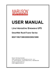
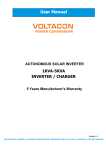
User's Manual
On-Line UPS
1000/2000/3000VA
R
Important Safety Instructions
THIS MANUAL CONTAINS IMPORTANT SAFETY INSTRUCTIONS.
PLEASE READ THIS MANUAL THOROUGHLY BEFORE ATTEMPTING TO UNPACK.
INSTALL OR OPERATE THE UPS.KEEP IT HANDY FOR FUTURE REFERENCE.
Important Safety Instructions
CAUTION
* SAVE THESE INSTRUCTIONS- This manual contains important instructions that
should be followed during installation and maintenance of the UPS and batteries.”
* “ Intended for installation in a controlled environment.”
* “ The maximum ambient temperature is 77 Deg F.”
* “ Servicing of batteries should be performed or supervised by personnel
knowledgeable of batteries and the required precautions .Keep unauthorized
personnel away from battery.”
* “ CAUTION- To reduce the risk of fire, connect only to a circuit provided with 20
amperes maximum branch circuit overcurrent protection in accordance with the
national electric code, “ANSI/NFPA”. The marking may be located internally
adjacent to wiring terminals or provided in the instruction manual”.
* “ Proper selection of power supply cord listed,rated minimum 14A,125V,cord type
SJT , No.14AWG/3C,one end terminates in a listed grounding type terminates in a
cord connector, minimum 6 ft long”.
CAUTION
* “ This unit should be installed by service personnel.”
* “ The equipment can be operated by any individuals with no previous
experience.”
* “ The socket-outlet shall be installed near the equipment and easily accessible.”
* “ With the installation of this equipment it should be prevented ,that the sum of
the leakage current of the UPS and the connected consumer dose not exceed
3.5mA.”
* “ Attention,hazardous through electric shock.Also with disconnection of this
unit from the main,hazardous voltage still may be accessible through supply
from battery.The battery supply should be therefore disconnected in the plus
and minus pole thought from the outer enclosure accessible battery fuse
when maintenance or service work inside the UPS.”
- 1-
Important Safety Instructions
Radio Frequency Interference ( RFI ) Notice
This equipment generates, uses and can radiate radio frequency energy.If not
installed and used in accordance with the instructions,this unit may cause
NOTE
harmful interference to radio communications.However,there is no guarantee
that interference will not occur in a particular installation.If this equipment does
cause harmful interference to radio or televison reception,which can be
determined by turning the equipment off and on,the user is encouraged to try to
correct the interference by one or more of the following measures:
Reorient or relocate the receiving antenna.
Increase the separation between the equipment and the receiver.
Connect the equipment into an outlet on a circuit different from that to which
the receiver is connected.
Consult with the dealer or an experienced Radio /TV technician for help.
Safe and continuous operation of the UPS depends partially on the care taken
CAUTION
by users.Please observe the following precautions.
* Do not attempt to power the UPS from any receptacle except a 2-pole-3-wire
grounded receptacle.
* Do not place the UPS near water or in environments of excessive humidity.
* Do not allow liquid or any foreign objects to get inside the UPS.
* Do not block air vents in front of the UPS or air exhausts on the back.
* Do not place the UPS under direct sunshine or close to heat-emitting
sources.
* Do not plug appliances such as hair dryers into the UPS receptacles.
* Do not disassemble the UPS.
* The power socket should be installed near the equipment.It should be easily
accessible to isolate it from AC input.To disconnect,pull the plug from the
receptacle.
- 2-
Table Of Contents
Table Of Contents
Important Safety Instructions
1. Introduction
4
1.1 System Description
4
1.2 Features
4
2. Installation and Operating Instructions
5
2.1 Unpacking & Inspection
5
2.2 Overview
5
2.3 Installation
7
2.4 Operation and Functional Test
9
2.5 Manual Simulation of Power Outage for the UPS
9
2.6 Operating Parameter Setting
10
2.6.1 Configuration Mode
10
2.6.2 Display and Control Switch
10
2.6.3 End of configuration Mode
11
2.6.4 Setting of Parameters
11
2.6.4.1 Display Parameter Configuration Stste
11
2.6.4.2 Cold Start Lock Setting
11
2.6.4.3 Output Frequency Setting
12
2.6.4.4 Output Voltage Setting
13
2.7 Operating Parameter Setting
13
3. Interface with Computer for UPS Status Monitoring
17
4. Service Maintenance
18
4.1 Routine Maintenance
18
4.2 Storage Instructions
18
5. Troubleshooting
19
6. Specifications
22
- 3-
Introduction
1.Introduction
1.1 System Description
The On-Line UPS are the most updated microprocessor-based digital controlled
sinewave online uninterruptible power systems which are designed to provide the high
efficiency in normal mode operation and prevent any spikes, surges, sags and blackouts
from reaching your sensitive equipment ,ranging from computer and telecommunication
systems to computerized instruments.
The monitoring software delivers data of the UPS operation,saves vital files
automatically on unattended shutdown,schedules on or off of the O/S on a daily or weekly
basis and logs in the status of the UPS for future reference.It can support multiple
operating systems.The optional SNMP/HTTP card allows your MIS department to monitor
and control the UPS in real time via a LAN system or Web Browser.
With the advancement in the information technology, an increasing number of server or
devices such as Modem, Hub and Router are susceptible to surge and spike from common
utility coming through the telephone line or LAN line; therefore, this series also have
added surge and spike protection for RJ11 and RJ45 connection. A complete protection
design,easy management software and affordable price make this series the best choice
for protecting the server.
1.2 Features
Double Conversion Design Provides High Reliability and Efficiency.
High Frequency Designs to Lower the Size and Weight.
Intelligent Microprocessor Control.
True Sine Wave Output.
User Configurable Output Voltage.
Smart Battery Reminder.
Self-Diagnostic Function can Provide Information for Troubleshooting Reference.
RJ11 Data/Fax Modem Connection Provides Surge Protection from Telephone.
100 Base T RJ45 Connection Provides Surge and Spike Protection for Network.
True RS232 of USB Signal for Power Management Software.
Optional SNMP/HTTP Card Connectivity for Remote Monitoring.
- 4-
Installation and Operating Instruction
2.Installation and Operating Instruction
2.1Unpacking&Inspection
Examine the packing carton for damage upon receipt.Once the UPS has been removed
from its shipping container,everything inside the package should be inspected for
damage that may have occurred while in transit .Notify the carrier immediately if any
damage is observed.
The box should include the following:
* UPS and Input Power Cord
CHECK
* User's Manual
* Telephone Communication Cable
* Remote Monitoring Software and Computer Series Interface Cable(optional)
Retain the packing for future use or dispose of properly.
2.2Overview
Item
1
2
3
4
Panel Indicator
Main On/OFF Switch
Beeper Silence and Self-test
Capacity Indicator
Fault Indicator
Description
Turn on/off UPS
UPS Silence and self-testing
LED bar shows approximate load and battery
Capacity (when in battery backup)
Displays UPS Fault/Continuous Red LED
5
AC Normal Indicator
Continuous Green LED displays AC utility
normal
6
AC Bypass Mode Indicator
Continuous Amber LED displays AC Bypass
Mode
7
Backup Mode/Battery Replace
Indicator
Continuous Red LED displays Battery Replace
and Flash backup mode
8
Output Indicator
Continuous Green LED displays UPS Output
9
External Battery Connector
(Extended models)
Provides connection port for external battery
cable
10
Input Circuit Breaker
Provides circuit overload and fault protection
for the UPS and load
11
DC Fan
For air cooling
- 5-
Installation and Operating Instruction
Item
Panel Indicator
Description
12
AC Inlet / Power cord
Connect to input power cord
13
AC outlet
Connect to load
14
Date Port: RS232 of USB
Communication Interface (Optional SNMP
card connectivity for remote Monitoring)
15
Tel / Fax / Modem (RJ15)
Suppress the spike voltage on the telephone line
16
Output Circuit Breaker
Provides circuit overload and fault protection
for the UPS and load
3
4
Battery
Load
6
25%
50%
75%
1
100%
5
TEST
2
8
7
Front Panel
15
15
14
16
14
11
11
13
13
10
12
9
10
1000VA
2000VA / 3000VA
120V Rear Panel
- 6-
9
12
Installation and Operating Instruction
15
15
14
14
11
11
13
10
12
9
1000VA
13
10
12
9
2000VA / 3000VA
230V with IEC 320 Rear Panel
2.3 Installation
Before installation, please read and understand the following instructions:
Placement
The UPS must be installed in a protected environment away from heat-emitting
appliances such as a radiator or heater. Do not install this product where
excessive moisture is present.
Ventilation
The location should provide adequate air flow around the UPS with one inch
minimum clearance on all sides for proper ventilation.
Charge the Battery
Your new UPS may be used immediately upon receipt. However charge loss
may occur during shipping and storage. So charging the battery for at least 8
hours is recommended to insure that the battery is fully charged.
To recharge the battery, simply leave the unit plugged into an AC outlet.
(This UPS will recharge in both the On and the Off status.)
- 7-
Installation and Operating Instruction
Connect to AC
Make sure that the voltage and frequency are correct. Plug the UPS into a 2
pole,3 wire grounding receptacle(wall outlet).Make sure the wall outlet branch
is protected. Avoid using extension cords at all possible. if used, make sure
the extension cord is rated for 15 Amps.
For 220/230/240V versions: swap the input power cord of the equipment to the
inlet of UPS. Use the power cord supplied with the UPS to connect from the
outlet of the UPS to your equipment.
Determining the Load:
1. Make a list of all equipment that requires protection.
2.Calculate the sum of all the V x A ratings.(Input voltage/current shown on
name plate).
3.Ensure that the total VA rating does not exceed the rated capacity of the
UPS.
If rated unit capacities are exceeded, an overload condition may occur and
cause the UPS unit to shut down or the circuit breaker to trip.
Do not plug a laser printer or copy machine into the outlets of this UPS.
The power demands of these particular devices are much higher than typical
NOTE
peripherals.
Connect the Load
Plug your primary equipment(e.g: computer, monitor, critical data storage
device, etc.)into the Battery Power Protected outlets. Leave the power
switches of the equipment in the “Off” position for the moment.
Connect to Computer
Use the enclosed RS-232 (DB9)cable or USB cable. Plug the 8-pin colorless male
end into the UPS.Plug the 9-pin female end into an open COM port on the computer
(9-pin Male).
Optional SNMP/HTTP Card Connectivity for Remote Monitoring.
Please check with your local dealer for the monitoring software.
Connect the Fax Lines
To protect a fax connect the telephone cable from the wall outlet to the “IN” jack of the
UPS. Connect the telephone cable from the “OUT “phone outlet on the UPS to the fax.
The phone jacks on the UPS accept standard sized phone cables ( RJ11 / RJ45
communication cables ).
- 8-
Installation and Operating Instruction
2.4 Operation and Functional Test
AC Mode
The UPS delivers power to the loads derived from the utility and maintains proper
battery charge. It also regulates the output voltage to within a narrow range and
serves to isolate the load from surges and electrical noise brought by the utility wiring.
On-Battery Mode
The UPS operates on battery when the line voltage or frequency has fallen outside
the limits. Local users are alerted to this mode of operation by visual and audible
indicators. The UPS provides power to the load from the battery and through its
inverter and the output voltage and frequency of the UPS are regulated within a
narrow band.
Function
Panel Indicator
Switch On
press and hold the main switch on the front panel for more than 2
seconds until the "AC normal" green LED lights up/"Bypass"
Amber LED lights up/"Inverter "green LED lights up. The UPS will
perform a self-test every time it is switched on.
Test
NOTE
Alarm Silence
Use the test function to check both the operation of the UPS and
the condition of the battery.
In AC operating mode,the level indicator will show the actual load
connected to this UPS normally.Press and hold the "Test" switch
on the front panel for more than 2 seconds,this UPS will enter into
testing mode. The battery will provide power to the load during this
period.Testing mode will check the status of battery and operation
of UPS,last for 10 seconds and transfer back to normal status
automatically.
Testing mode can not performed if the load connected is greater
than overload or the charging voltage is lower than
22Vdc (model:700W/1000VA) or 88Vdc (model:2100W/3000VA).
In battery backup mode, the level indicator will show the battery
capacity level and the alarm beeps normally. Press and hold the
" Test "switch on the front panel for more than 2 seconds. The
alarm will be silenced. The alarm can be activated again by
repeating the same procedure show in this paragraph. Under
silence model, press silence key , the alarm will be silent. When
it happens low battery , overload or second utility power cut off,
the alarm silence will be activated again.
2.5 Manual Simulation of Power Outage for the UPS
To test the backup function, you may unplug the power cord of the UPS or simply press
the main switch button on the front panel. The UPS will beep once every 4 seconds and
the backup mode LED will turn on. You can press the main switch again to silence the
audible alarm.
- 9-
Installation and Operating Instruction
If the UPS is left to run continuously, it is a good idea to perform a periodic function test
on the unit ( at least once a week ).To perform this test simply press the test button on the
front of the UPS or unplug the power cord to the UPS to simulate a utility blackout.
Observe that your equipment operates properly and uninterrupted during this period.
Plug the power cord back in if the function test was performed by unplugging it.
To conduct a simulation-test:
Switch the UPS on and wait for the Power On indicator to light up.
Then unplug the UPS from the AC outlet to simulate a utility failure.
When utility failure occurs, power is immediately supplied to your equipment from the
UPS battery. The alarm will beep once every 4 seconds, reminding you that your
equipment is running on a limited power source.
Unless shutdown software has been installed, during utility failure, manually save
and close the files you are currently working on. Then, switch the UPS off to conserve
the battery power for additional testing and usage.
If the utility power is not restored, the alarm will change to rapid beeps alerting the
user that the UPS will soon run out of battery power and will shut itself down.
Restore electrical power to connected equipment by re-plugging the UPS power cord
into a wall outlet.
Backup all unsaved files before you perform the power outage simulation test.
NOTE
2.6 Operating Parameter Setting
2.6.1 Configuration Mode
Press and hold both the main switch “
” and“ Test / Silence ” switch on the front panel
for more than 2 seconds while the UPS is in the off status. The UPS will now enter
parameter configuration mode. (Mode indicator is Fault LED )
Level Indicator
Status Indicator
2.6.2 Configuration Mode
When the UPS enters into the configuration mode, the turn on of six different status in
dicator LEDs represent different parameter being programmed.
- 10-
Installation and Operating Instruction
Different parameter can be selected by press the “ Test / Silence ”switch for 1 time.
Different settings can be selected by pressing the main switch “ ” for 1 time.
2.6.3 End of configuration mode
To exit the configuration mode:
Press and hold both the main switch “
” and“ Test / Silence ” switch for more than 2
seconds.
*( If you need execute the end program, please make battery led getting light up with
the options button.)
2.6.4 Setting of Parameters
2.6.4.1Display Parameter Configuration State
Press and hold both the main switch “
” and“ Test / Silence ” switch on the front
panel for more than 2 seconds while the UPS is in the off status. The UPS will now
enter parameter configuration mode.
Now ,The battery LED of status indicator light up, Level indicator demonstrate
present establish state or dispatched from the factory and established the state
Please consult the following brief description of the drawings.
NOTE
UPS output voltage state
UPS output frequency state
Cold start lock function state
LED flashing is into setting mode
Selection setting state indicator
-LED light up
2.6.4.2 Cold Start Lock Setting
Press the “ Test / Silence “switch to
select the cold start lock setting mode.
Selection cold state lock indicator-Line LED light up
Press the main switch “
" to select cold start lock function Enable / Disenable.
- 11-
Installation and Operating Instruction
LED1 On (Ignore LED2,LED3,LED4,LED5)
Cold start Lock = Enable
LED1 Off (Ignore LED2,LED3,LED4,LED5)
Cold start Lock = Disable
Accidental turn on during transportation may result in battery and UPS
damage. Therefore the feature of cold-start (boost by battery)is factory
NOTE
defaulted to inactivation. To activate the cold-start feature, you can choose
the following a way among them.
1.Plug in AC power and turn on the UPS.
2.Manual setting
2.6.4.3 Output Frequency Setting
Press the “ Test / Silence “switch to select the UPS output frequency setting mode.
Selection output frequency indicator
-Bypass LED light up
Press the main switch “
" to select output frequency 50Hz/60Hz.
LED2 On (Ignore LED1,LED3,LED4,LED5)
Output Frequency = 60Hz
LED2 Off (Ignore LED1,LED3,LED4,LED5)
Output Frequency = 50Hz
This UPS is with auto sensing feature which will automatically detect the
utility's frequency. The frequency setting parameter will be automatically
NOTE
replaced by the UPS.
For example, the 50Hz was set as in the UPS, the setting will be changed to
60 Hz if the utility's frequency is 60 Hz.
- 12-
Installation and Operating Instruction
2.6.4.4 Output Voltage Setting
Press the “ Test / Silence “switch to select the UPS output voltage setting mode.
Selection output voltage indicator
-Inverter LED light up
Press the main switch “
" to select output voltage.
LED3/4 Off (Ignore LED1,LED2,LED5)
Output Voltage = 120V / 230V
LED3 On ,LED4 Of (Ignore LED1,LED2,LED5)
Output Voltage = 110V / 208V
LED3 Off, LED4 On (Ignore LED1,LED2,LED5)
Output Voltage = 115 / 220V
LED3/4 On (Ignore LED1,LED2,LED5)
Output Voltage = 127V / 240V
2.7 Audible / Visual Indicators
Audible / Visual Indicators
Operating Status
Buzzer
AC Input ( UPS Off )
Site Wire Fault (115 V)
AC Normal
Backup mode
1 Beep / 4 Seconds
Backup mode (Batty Low)
1 Beep / 1 Seconds
- 13-
Installation and Operating Instruction
Battery Capacity Indicators (Backup Mode)
LED1 LED2 LED3 LED4 LED5 LED6
LED Code Explain
NOTE
=Continuously Lit
Buzzer
Operating Status
1 Beep / 4 Seconds
Battery capacity=100%
1 Beep / 4 Seconds
Battery capacity=75%
1 Beep / 4 Second
Battery capacity=50%
1 Beep / 1 Second
Battery capacity=25%
LED Code Explain
= 1 Flash Every
0.1 Seconds
=OFF Status
Load Size Indicators (AC Normal)
LED1 LED2 LED3 LED4 LED5 LED6
Buzzer
Operating Status
Load size 25%
Load size 50%
Load size 75%
Load size 100%
- 14-
2 Beeps / 1 Second
Load = 105 ~125 %.
1 minute later UPS
transfer to Bypass.
2 Beeps / 1 Second
Load = 126 ~150 %.
10 seconds later
UPS transfer to
Bypass.
2 Beeps / 1 Second
Load > 150% .UPS
Immediately
transfer To Bypass.
Installation and Operating Instruction
(Backup Mode)
LED1 LED2 LED3 LED4 LED5 LED6
LED Code Explain
NOTE
=Continuously Lit
Buzzer
Operating Status
2 Beeps / 1 Second
Load = 105 ~125 %.
1 minute later UPS
shutdown.
2 Beeps / 1 Second
Load = 126 ~ 150%.
10 seconds later
UPS shutdown.
2 Beeps / 1 Second
Load > 150% .UPS
Immediately
Shutdown.
LED Code Explain
= 1 Flash Every
0.1Seconds
=OFF Status
Abnormal Status Indicators
LED1 LED2 LED3 LED4 LED5 LED6
Buzzer
Operating Status
Beep continuously
Output circuit short
Beep continuously
Inverter over voltage
Beep continuously
Inverter under voltage
Beep continuously
Over temperature
Beep continuously
Charger over voltage
Beep continuously
Charger fault
Beep continuously
Bus over/under
Voltage abnormal
Beep continuously
Fan lock fault
- 15-
Installation and Operating Instruction
LED Code Explain
NOTE
=Continuously Lit
LED Code Explain
= 1 Flash Every
0.1Seconds
=OFF Status
The buzzer alarm can be disabled by pressing the main on switch in backup mode.
Alarm silence function can not be performed when the battery voltage is lower
NOTE
- 16-
or the UPS is abnormal status.
Installation and Operating Instruction
3.Installation and Operating Instruction
The communication port on the back of the UPS may be connected to a host
computer. This port provides two different methods for communicating with the
computer.
Method 1 (SNMP-Option):
This UPS communicates with the computer by Ethernet sending out TCP/IP
protocol monitor. Using this method the user is able to monitor the following
parameters:
Method 2 (True RS-232):
This UPS communicates with the computer by sending out RS-232 data
streams to one of the serial ports. Using this method the user is able to
monitor the following parameters:
Pin Assignment:
Pin #
Description
Pin 1
DTR +5~12Vdc (RTS).
Pin 2
N.C.
Pin 3
N.C.
Pin 4
N.C.
Pin 5
N.C.
Pin 6
This pin is used for RS232 receive pin(RXD).
Pin 7
Common ground for pins 6 and 9.
Pin 8
N.C.
Pin 9
This pin is used for RS232 transmission pin(TXD).
Some computers are equipped with a special connector to link the UPS communication
port to the computer. Contact your dealer for details on software and all the various
interface kits.
- 17-
Service and Maintenance
4.Service and Maintenance
4.1 Routine Maintenance
* Use dry soft cloths to clean the front panel and plastic parts.
CHECK
* Do not use any detergent that contains alcoholic ingredient.
* The expected lifetime of the battery is around 3-5 years. Improper operation or
harsh environment will reduce the actual lifetime.
* Unplug the UPS from power inlet if the UPS will not operate for long period of
time.
* Charge the battery every 3 months to recover the self-discharge capacity when
the UPS is in extended storage.
* When replacing batteries, use the sealed lead-acid maintenance free battery
with the same number and capacity.
* Proper disposal of batteries if required. Refer to your local codes for disposal
requirements.
4.2 Storage Instructions
The UPS should be stored in a cool dry location. Make sure the battery is fully charged
before the UPS is stored.
For extended storage in moderate climates, the battery should be charged for 12 hours
every 3 months by plugging the power cord into the wall receptacle and turning on the
main switch. Repeat every 2 months in high temperature.
- 18-
Troubleshooting
5. Troubleshooting
The TROUBLESHOOTING TABLE in the next page covers most of the difficulties that you
may encounter under normal working conditions. If the UPS fails to operate properly,
please review the following steps before calling the repair center:
1.Is the UPS plugged into a proper working outlet?
2.Is the line voltage within the rating specified?
3.Does the fuse on the rear panel need to be replaced?
Please do not open the metal cover.
There are no user serviceable parts inside.
The batteries contained in this UPS are recyclable.
The batteries contain lead and pose a hazard to the environment and
human health If not disposed of properly.
* Do not open or mutilate the batteries. They contain an electrolyte which is
toxic and harmful to the skin and eyes.
CAUTION
* A battery can present a risk of electrical shock and high short circuit current.
When replacing batteries, wrist watches and jewelry such as rings should be
removed. Use tools with insulated handled.
Please note the following information when you call for service:
1.Model No. / Serial No.
NOTE
2.Date of purchase.
3.Full description of problem.
5.1 Trouble Shooting Table
Abnormal Situation
Cause
UPS can not turn on and On / Off switch not pushed or
LED not lit
pushed less than 2 seconds
Battery voltage is too low
Power cord loose
UPS always at battery
mode
Input circuit breaker tripped
Line voltage over range
Line frequency over range
Solution
Press and hold the main switch
for more than 2 seconds
Recharge the battery for at least
4 hours
Re-plug the power cord firmly
Remove some loads and reset
circuit breaker
Check input voltage
Check input frequency
- 19-
Troubleshooting
Abnormal Situation
Cause
UPS is normal but the
computer won't turn on
Computer input power cord is
loose or not connected
Backup time is less than Battery is not fully charged or
battery is dead
the rating
AC fail, UPS automatic
turn off
Solution
Reconnect computer input
power cord
Recharge the battery for 6 hours
and re-test the backup time. If
problem remains, call for service
UPS is slightly overloaded
Remove the least critical load
Battery is not fully charged or
battery is dead
Recharge the battery for 6 hours
and re-test the backup time. If
problem remains, call for service
UPS is over load shuts
down
Remove non-critical load and
start the UPS again and recharge
the battery for 6 hours
The UPS 2 beeps in every UPS is at overload
second and LED5 flash
Remove the non-critical loads
During AC fail, the UPS 2 Backup mode UPS is over
beeps in every second loaded, unit will shuts down in
LED5 lit
the same time
Remove non-critical loads and
start the UPS again
AC is normal, the UPS 2
beeps in every second
LED5 lit
AC mode UPS is over loaded,
unit will transfer to Bypass
Remove the non-critical loads
Site Wiring problem
Call an electrician to check your
wiring
Site Wiring Fault LED
flash
5.1 Trouble Shooting Table
Abnormal Situation
Communication function
not working
Battery and Load level
LED 1,2,4,6 lit
Battery and Load level
LED 1,2,6 lit
Battery and Load level
LED 1,3,6 lit
Battery and Load level
LED 1,4,6 lit
Battery and Load level
LED 1,3,4,6 lit
Battery and Load level
LED 1,5,6 lit
Battery and Load level
LED 1,3,5,6 lit
Battery and Load level
LED 1,2,5,6 lit
Heard beeps 2 time at
UPS turn on
Cause
Solution
Wrong interface cable
Purchase the correct one from
your distributor
UPS output short fault
Please check output circuit
UPS inverter over voltage
Call for service
UPS inverter under voltage
Call for service
UPS over temperature
Remove the UPS to provide
adequate air flow area
UPS DC Fan fault
Please check DC fan of UPS
Charger over voltage
Call for service
Charger fail
Call for service
Bus over / under voltage
Call for service
Cold start lock enable
Please use manual setting
disenable UPS cold start lock
Plug in AC power and turn on the
UPS
- 20-
Troubleshooting
Abnormal Situation
Heard beeps 3 time at
UPS turn on
Heard beeps 4 time at
UPS turn on
Heard beeps 5 time at
UPS turn on
Solution
Cause
Battery voltage too low at
Cold start UPS
Plug in AC power and turn on the
UPS
DC Fan fault
Call for service
UPS over heat
Remove the UPS or clean DC fan
to provide adequate air flow area
Call for service
It is suggested that the battery replacement should be conducted by an
authorized technician and with the same type and capacity of battery.
NOTE
System Fault
Charge Status
LOAD CAPACITY
Normal Mode
AC NORMAL
Load Condition
ABNORMAL
BATTERY CAPACITY
Battery Condition
Input Status
Output Status
Frequency
Battery Mode
BATT. MODE
CHARGING
BY PASS
OVER LOAD
Bypass Mode
Voltage Power
Over Load
Ampere
Multi-function Meter & Error Message
*. LCD Panel Switch
Each press of the switch will lead to a UPS status and data. The LCD can indicate that
the UPS is Normal Mode, Battery Mode, Bypass Mode, Internal Fault, Charge,
Overload, Load Capacity, Battery Capacity and show each data.
- 21-
Specification
6. Specification
Capacity
1000VA
2000VA
Topology
3000VA
Double Conversion
Nominal Voltage
120Vac / 230Vac( 110,115,120,127Vac/
208,220,230,240Vac Configurable)
Voltage Range
60~138Vac /120~276Vac
Input
Frequency Range
50 /60Hz ± 0.5Hz ( Auto-sensing )
>0.95 ( full load condition )
Power Factor
Nominal Voltage
120Vac / 230Vac ( 110,115,120,127Vac/
208,220,230,240Vac Configurable)
Voltage Regulation
+3% ( Non-Linear Load )
Frequency Stability
50 /60Hz ± 0.3Hz ( Battery Mode )
Waveform
True Sine Wave
Power Factor
0.7 lagging to 1
Output
<5% ( Non-Linear Load )
Distortion
Overload Capacity
105~125% for 1 min./ 126~150% for 10 sec./>150% Trip Immediately
@AC mode, UPS transfer to bypass/ @Battery mode, UPS shutdown
0 ms
Transfer Time
Type
DC Voltage
Battery
Backup Time
Sealed, Maintenance-free Lead Acid
24Vdc
72Vdc
96Vdc
3~30 Min
4.5~40 Min
4.5~45 Min
External Battery
Connector
Charger
Option
Charging voltage
Standard
Extended
27.6V ± 0.3V
27.0V ± 0.3V
82.5V ± 0.5V
82.5V ± 0.5V
110V ± 0.5V
110V ± 0.5V
Charging current
Standard
Extended
1.0A max
8.0A max
0.8A max
10.0A max
0.8A max
10.0A max
Recharge Time
Power Line
Surge
Suppression
EMI / RFI Noise
Filter
- 22-
Joules
< 8 Hour Recovery to 90%
250 Joules
375 Joules
Up to 60 Db ( @1MHz )
375 Joules
Specification
Capacity
1000VA
2000VA
Joules
TEL/FAX Surge
Suppression
54 Joules
Clamping Rating
395V
Type
Networking Surge
Suppression
Indicators
Communication
Physical
LAN Surge Suppression
Type
TVS-1.5KE 6.8A
Line Normal(Green),Bypass (Amber),Inverter(Green),
Battery Backup (Red),Fault(Red),Overload(Amber),
Load/Battery Capacity (Green ×4pcs ) Site Wiring Fault
LED same as Line Normal LED(115Vac Model Only)
Fault Message
Display by Load / Battery Capacity LED (×5pcs )
Audible Alams
Battery Backup (Every 4 Seconds),Battery Low (Every
Second). Overload (Twice Every Second ),
Fault (Continuously)
Intelligent
Interface
Compatible O/S
Environment
RJ11( One Pair ),2C
Performance
Front Panel LEDs
3000VA
Ambient
Operation
Audible noise
Dimension
(L*W*H)in
Net Weight (lbs)
RS-232 Signal (Standard);SNMP /HTTP Card (Optional)
Windows 95/ 98 /2000/NT /XP, Linux, Novell, Unix,
SNMP, HTTP
3000Meters max Elevation 0~95%Humidity,
Non-condensing0~40
<45dB (1 meter
from surface )
6.3x17.24x8.88
7.64x18.01x13.82 7.64x18.01x13.82
27.78
68.34
69.45
* Specifications subject to change without prior notice
* Input voltage range for engineering specifications
* Output voltage and current, please reference UPS specifications label
- 23-
R
Maruson Technology Corp.
P.O. Box 1986, Walnut, CA 91788, U.S.A.
Toll Free: 1-888-MARUSON
E-mail: [email protected]
Web Site: www.marusonusa.com