1
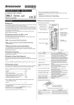
HM-40093-3 O P E R AT I N G M A N U A L Thank you for purchasing an Oriental Motor product. This Operating Manual describes product handling procedures and safety precautions. yyPlease read it thoroughly to ensure safe operation. yyAlways keep the manual where it is readily available. Closed loop stepping motor and driver package AR Series DC power input Pulse input type Driver Operating Manuals for the AR Series Manual name Motor function Driver function Installing Installing the motor the driver AR Series Motor OPERATING MANUAL (Supplied with motor) ○ − ○ AR Series DC power input Pulse input type Driver OPERATING MANUAL (this document) − ○ AR Series DC power input Pulse input type USER MANUAL ○ ○ Connection Operation Troubleshooting − − − − − ○ ○ − − ○ ○ ○ ○ ○ The "USER MANUAL" does not come with the product. For details, contact your nearest Oriental Motor sales office or download from Oriental Motor website download page. Introduction Names of parts use Before Only qualified personnel should work with the product. Use the product correctly after thoroughly reading the section "Safety precautions.” The product described in this manual has been designed and manufactured for use in general industrial equipment. Do not use for any other purpose. Oriental Motor Co., Ltd. is not responsible for any damage caused through failure to observe this warning. substances Hazardous The products do not contain the substances exceeding the restriction values of RoHS Directive (2011/65/EU). the product Checking Verify that the items listed below are included. Report any missing or damaged items to the branch or sales office from which you purchased the product. Current setting switch POWER LED ALARM LED Data edit connector (CN4) Motor connector (CN2) Speed filter setting switch Resolution switches (SW1-No.3/No.4) Control mode select switch (SW1-No.2) Pulse input mode select switch (SW1-No.1) I/O signals connector (CN5) Main power supply input terminals (CN1) Frame Ground Terminal (CN1) DIN lever yy Driver.........................................................................1 unit yy CN1 connector (3 pins).............................................1 pc. yy CN5 connector (36 pins)...........................................1 pc. yy OPERATING MANUAL Driver (this document).........1 copy 1 Installation method Installation for installation Location Mount the driver to a 35 mm (1.38 in.) width DIN rail. The driver has been designed and manufactured to be installed within another device. Install them in a well-ventilated location that provides easy access for inspection. The location must also satisfy the following conditions: 35 (1.38) 90 (3.54) 25 (0.98) or more yy Inside an enclosure that is installed indoors (provide vent holes) yy Operating ambient temperature 0 to +50 °C [+32 to +122 °F] (non-freezing) yy Operating ambient humidity 85% or less (non-condensing) yy Area that is free of explosive atmosphere or toxic gas (such as sulfuric gas) or liquid yy Area not exposed to direct sun yy Area free of excessive amount of dust, iron particles or the like yy Area not subject to splashing water (rain, water droplets), oil (oil droplets) or other liquids yy Area free of excessive salt yy Area not subject to continuous vibration or excessive shocks yy Area free of excessive electromagnetic noise (from welders, power machinery, etc.) yy Area free of radioactive materials, magnetic fields or vacuum yy 1000 m (3300 ft.) or lower above sea level 10 (0.39) or more [Unit: mm (in.)] Note yy Install the driver in an enclosure whose pollution degree is 2 or better environment, or whose degree of protection is IP54 minimum. yy Do not install any equipment that generates a large amount of heat or noise near the driver. yy Do not install the driver underneath the controller or other equipment vulnerable to heat. yy Check ventilation if the ambient temperature of the driver exceeds 50 °C (122 °F). yy Be sure to install the driver vertically (vertical position). Connection The following figure is a connection example when an electromagnetic brake motor is used. Electromagnetic brake cable Cable for electromagnetic brake Switch White Black DC power supply* 24 VDC±5% Varistor (supplied) Model AR24 AR26 AR46 AR66 AR69 AR98 Cable for OPX-2A or MEXE02 Motor cable Power supply current capacity 0.05 A or more 0.08 A or more 0.25 A or more Cable for motor Connector screw size: M2.5 Tightening torque: 0.4 N·m (56 oz-in) Main power supply I/O signals 7 mm (0.28 in.) Applicable lead wire AWG24 to 16 (0.2 to 1.25 mm2) 18 17 2 36 35 20 19 1 +24 VDC GND FG 2 * The power supply current capacities are as follows. Connector screw size: M2 Tightening torque: 0.22 to 0.25 N·m (31 to 35 oz-in) CN1 connector Lead wire Tightening torque: 0.3 to 0.35 N·m (42 to 49 oz-in) Applicable lead wire AWG28 to 26 (0.08 to 0.14 mm2) connector pin assignment power supply current capacity I/O Main Model Input power supply voltage Power supply current capacity 0.4 A or more AR14 AR15 AR24 AR26 24 VDC±10% 0.9 A or more AR46 AR66 AR69 0.5 A or more 24 VDC±10% 48 VDC±5% AR98 Pin No Operating mode Positioning operation Push-motion operation *1 − − 2 GND Ground connection A-phase pulse output (Line driver) 3 ASG+ 4 ASG− 3.1 A or more 5 BSG+ 3.0 A or more 6 BSG− 2.5 A or more 7 TIM1+ 8 TIM1− z zGeneral yy Have the connector plugged in securely. Insecure connector connection may cause malfunction or damage to the motor or driver. yy When cycle the power or plugging/unplugging the connector, turn off the power and wait for the POWER LED to turn off. z the motor zConnecting yy When unplugging the connector, do so while pressing the latches on the connector. yy When installing the motor to a moving part, use an accessory flexible cable offering excellent flexibility. yy If the distance between the motor and driver is extended to 20 m (65.6 ft.) or longer, use a power supply of 24±4% VDC. yy The lead wires of the "cable for electromagnetic brake" have polarities, so connect them in the correct polarities. If the lead wires are connected with their polarities reversed, the electromagnetic brake will not operate properly. z the I/O signals zConnecting yy Be certain the I/O signals cable is as short as possible. The maximum input frequency will decrease as the cable length increases. z the power supply zConnecting Do not wire the power supply cable of the driver in the same cable duct with other power line or motor cable. Doing so may cause malfunction due to noise. Pay attention to the polarity of the power supply. Reversepolarity connection may cause damage to the driver. The main power supply connector (CN1), data edit connector (CN4) and I/O signal connector (CN5) of the driver are not electrically insulated. When grounding the positive terminal of the power supply, do not connect any equipment (PC, etc.) whose negative terminal is grounded. Doing so may cause the driver and these equipment to short, damaging both. Push-motion operation *1 1 1.4 A or more about connection Notes Name Positioning operation B-phase pulse output (Line driver) Timing output (Line driver) 9 ALM+ 10 ALM− 11 WNG+ 12 WNG− 13 END+ 14 END− 15 READY+/AL0+ *1 16 READY−/AL0− *1 17 TLC+/AL1+ *1 18 TLC−/AL1− *1 19 TIM2+/AL2+ *1 20 TIM2−/AL2− *1 Timing output (Open collector)/Alarm code output 2 21 GND Ground connection 22 IN-COM Input common 23 C-ON *2 Current ON input 24 CLR/ALM-RST Deviation clear input/ Alarm reset input 25 CCM Current control mode ON input Alarm output Warning output Positioning completion output 26 CS T-MODE *1 27 − M0 *1 28 RETURN M1 *1 29 P-RESET M2 *1 Operation ready complete output/Alarm code output 0 Torque limit output/ Alarm code output 1 Resolution Push-motion selection input operation ON − Return to Push-current electrical home setting operation selection input Position reset input 30 FREE Excitation OFF 31 CW+/PLS+ 32 CW−/PLS− CW pulse input/Pulse input (+5 V or line driver) 33 CW+24 V/PLS+24 V CW pulse input/Pulse input (+24 V) 34 CCW+24 V/DIR+24 V CCW pulse input/Direction input (+24 V) 35 CCW+/DIR+ 36 CCW−/ DIR− CCW pulse input/Direction input (+5 V or line driver) *1The signal will become effective if the applicable setting has been changed using the accessory OPX-2A (sold separately) or MEXE02. *2Factory setting of the C-ON input logic is "normally open." Be sure to turn the C-ON input ON when operating the motor. Set the C-ON input logic to "normally closed" when the C-ON input is not used. 3 Safety precautions Setting Current setting switch (Factory setting: F) Set a desired operating current. The operating current to be set is the maximum output current multiplied by the operating current rate (%). Speed filter setting switch (Factory setting: 1) The motor response to input pulses can be adjusted. Resolution switch (Factory setting: OFF) Set a desired resolution per revolution of the motor output shaft. Keep this switch in the OFF position. Pulse input mode select switch Set a desired pulse input mode of the driver. OFF: 2-pulse input mode ON: 1-pulse input mode Note yy The new settings of the resolution switches or pulse input mode select switch will become effective after the power is cycled. yy Excessively low operating current may cause a problem in starting the motor or holding the load in position. Do not lower the operating current more than necessary. yy When changing the resolution using the CS input, use the switches in "No.3: OFF"/"No.4: OFF" or "No.3: OFF"/"No.4: ON" combination. If the CS input is turned ON when "No.3: ON" is selected, the resolution will not be changed. z zResolution OFF OFF ON OFF OFF Resolution 1000 P/R (Factory setting) ON ON ON Resolution 500 P/R Resolution 10000 P/R Resolution 5000 P/R The precautions described below are intended to prevent danger or injury to the user and other personnel through safe, correct use of the product. Use the product only after carefully reading and fully understanding these instructions. Handling the product without observing the instructions that accompany a "Warning" symbol may result in serious injury or death. General yy Do not use the product in explosive or corrosive environments, in the presence of flammable gases, locations subjected to splashing water, or near combustibles. Failure to do so may result in fire or injury. yy Assign qualified personnel the task of installing, wiring, operating/controlling, inspecting and troubleshooting the product. Failure to do so may result in fire, injury or damage to equipment. yy When the driver generates an alarm (protective functions is triggered), take measures to hold the moving part in place since the motor stops and loses its holding torque. Failure to do so may result in injury or damage to equipment. yy When the driver generates an alarm (protective functions is triggered), first remove the cause and then clear the protection function. Continuing the operation without removing the cause of the problem may cause malfunction of the motor and driver, leading to injury or damage to equipment. Installation yy Install the driver in the enclosure in order to prevent injury. z current zOperating Connection Dial setting Operating current rate (%) Dial setting Operating current rate (%) 0 6.3 8 56.3 1 12.5 9 62.5 2 18.8 A 68.8 3 25.0 B 75.0 4 31.3 C 81.3 87.5 5 37.5 D 6 43.8 E 93.8 7 50.0 F 100 (Factory setting) filter z zSpeed Dial setting 4 Speed filter time constant (ms) Dial setting Speed filter time constant (ms) 30 0 0 8 1 1 (Factory setting) 9 50 2 2 A 70 3 3 B 100 4 5 C 120 5 7 D 150 6 10 E 170 7 20 F 200 yy Keep the driver's input power voltage within the specified range. Failure to do so may result in fire. yy For the driver’s power supply, use a DC power supply with reinforced insulation on its primary and secondary sides. Failure to do so may result in electric shock. yy Connect the cables securely according to the wiring diagram. Failure to do so may result in fire. yy Do not forcibly bend, pull or pinch the cable. Doing so may cause fire. Operation yy Turn off the driver power in the event of a power failure. Or the motor may suddenly start when the power is restored and may cause injury or damage to equipment. yy Do not turn the FREE input to ON while the motor is operating. The motor will stop and lose its holding power. Doing so may result in injury or damage to equipment. Repair, disassembly and modification yy Do not disassemble or modify the driver. Doing so may cause injury. Refer all such internal inspections and repairs to the branch or sales office from which you purchased the product. Precautions for use Handling the product without observing the instructions that accompany a “Caution” symbol may result in injury or property damage. General yy Do not use the driver beyond its specifications. Doing so may result in injury or damage to equipment. yy Keep your fingers and objects out of the openings in the driver. Failure to do so may result in fire or injury. yy Do not touch the driver during operation or immediately after stopping. The surface is hot and may cause a skin burn(s). Installation yy Do not leave anything around the driver that would obstruct ventilation. Doing so may result in damage to equipment. Connection yy The main power supply connector (CN1), data edit connector (CN4) and I/O signal connector (CN5) of the driver are not electrically insulated. When grounding the positive terminal of the power supply, do not connect any equipment (PC, etc.) whose negative terminal is grounded. Doing so may cause the driver and these equipment to short, damaging both. Operation yy Use a motor and driver only in the specified combination. An incorrect combination may cause a fire. yy Provide an emergency stop device or emergency stop circuit external to the equipment so that the entire equipment will operate safely in the event of a system failure or malfunction. Failure to do so may result in injury. yy Before supplying power to the driver, turn all input signals to the driver OFF. Otherwise, the motor may start suddenly at power ON and cause injury or damage to equipment. yy Before moving the motor directly with the hands, confirm that the FREE input turns ON. Failure to do so may result in injury. yy Immediately when trouble has occurred, stop running and turn off the driver power. Failure to do so may result in fire or injury. Disposal yy To dispose of the driver, disassemble it into parts and components as much as possible and dispose of individual parts/components as industrial waste. This section covers limitations and requirements the user should consider when using the product. •• Always use the cable (supplied or accessory) to connect the motor and driver. Be sure to use the cable (supplied or accessory) to connect the motor and driver. In the following condition, an appropriate accessory cable must be purchased separately. yy If a flexible cable is to be used. yy If a cable of 3 m (9.8 ft.) or longer is to be used. yy If a motor and driver package without a cable was purchased. •• Perform the insulation resistance test or dielectric strength test separately on the motor and the driver. Performing the insulation resistance test or dielectric strength test with the motor and driver connected may result in damage to the product. •• Saving data to the NV memory Do not turn off the main power supply while writing the data to the NV memory and 5 seconds after the completion of writing the data. Doing so may abort writing the data and cause a EEPROM error alarm to generate. The NV memory can be rewritten approx. 100,000 times. •• Motor excitation at power ON Simply turning on the power will not excite the motor. To excite the motor, always turn the C-ON input ON. It is possible to set the motor to be excited automatically after the power has been turned on, by changing the applicable driver parameter using the accessory OPX-2A (sold separately) or MEXE02. •• Overvoltage alarm by regeneration energy The overvoltage alarm will generate depending on the operating condition. When an alarm is generated, review the operating conditions. •• Note on connecting a power supply whose positive terminal is grounded The main power supply connector (CN1), data edit connector (CN4) and I/O signal connector (CN5) of the driver are not electrically insulated. When grounding the positive terminal of the power supply, do not connect any equipment (PC, etc.) whose negative terminal is grounded. Doing so may cause the driver and these equipment to short, damaging both. Use the accessory OPX-2A (sold separately) to set data, etc. •• Do not perform push-motion operation with geared types. Doing so may cause damage to the motor or gear part. 5 General specifications Operation environment Storage environment Shipping environment Degree of protection IP20 Ambient temperature 0 to +50 °C (+32 to +122 °F) (non-freezing) Humidity 85% or less (non-condensing) Altitude Up to 1000 m (3300 ft.) above sea level Surrounding atmosphere No corrosive gas, dust, water or oil Ambient temperature −20 to +60 °C (−4 to +140 °F) (non-freezing) Humidity 85% or less (non-condensing) Altitude Up to 3000 m (10000 ft.) above sea level Surrounding atmosphere No corrosive gas, dust, water or oil Combinations of motors and drivers yy will be filled with A (single shaft), B (double shaft) or M (with electromagnetic brake). For AR14S and AR15S, indicates A (single shaft) or B (double shaft). For geared type, indicates A (single shaft) or M (with electromagnetic brake). yy represents a number indicating the gear ratio. yy indicates the cable length (-1, -2, -3) when the connection cable is supplied. z geared type zPS z type zStandard Model Motor model Driver model Model Motor model AR14SK ARM14SK AR24SAK-PS ARM24SAK-PS AR15SK ARM15SK AR46SK-PS ARM46SK-PS AR24SK ARM24SK AR46K-PS ARM46K-PS AR26SK ARM26SK AR66SK-PS ARM66SK-PS AR46SK ARM46SK AR66K-PS ARM66K-PS AR46K ARM46K AR98SK-PS ARM98SK-PS AR98K-PS ARM98K-PS AR66SK ARM66SK AR66K ARM66K AR69SK ARM69SK AR69K ARM69K AR98SK ARM98SK AR98K ARM98K ARD-K Motor model Model AR24SAK-N Driver model Motor model AR46SK-N ARM46SK-N AR46K-N ARM46K-N AR66SK-N ARM66SK-N AR66K-N ARM66K-N AR24SK-T ARM24SK-T AR98SK-N ARM98SK-N ARM46SK-T AR98K-N ARM98K-N AR46K-T ARM46K-T ARM66SK-T ARD-K ARD-K z geared type zHarmonic AR66K-T ARM66K-T AR98SK-T ARM98SK-T AR24SK-H ARM24SK-H AR98K-T ARM98K-T AR46SK-H ARM46SK-H 6 Driver model ARM24SAK-N AR46SK-T AR66SK-T ARD-K z geared type zPN z geared type zTH Model Driver model Model Motor model AR46K-H ARM46K-H AR66SK-H ARM66SK-H AR66K-H ARM66K-H AR98SK-H ARM98SK-H AR98K-H ARM98K-H Driver model ARD-K CE Marking Voltage Directives Low Because the input power supply voltage of this product is 24 VDC/48 VDC, it is not subject to the Low Voltage Directive but install and connect this product as follows. yy This product is designed and manufactured to be installed within another device. Install the product in an enclosure. yy For the driver power supply, use a DC power supply with reinforced insulation on its primary and secondary sides. Directive EMC This product has received EMC compliance under the conditions specified in “Example of motor and driver installation and wiring” on USER MANUAL. Since the compliance of the final machinery with the EMC Directive will depend on such factors as the configuration, wiring, layout and risk involved in the control-system equipment and electrical parts, it therefore must be verified through EMC measures by the customer of the machinery. •• Applicable Standards EMI EN 61000-6-4 EN 61800-3 EN 55011 group 1 class A EMS EN 61000-6-2 EN 61800-3 Input/output power ratings Frame size [mm (in.)] 20 (0.79) Model Motor model AR14 ARM14 AR15 ARM15 28 (1.10) 30 (1.18) AR24 ARM24 AR26 ARM26 42 (1.65) AR46 ARM46 AR66 ARM66 AR69 ARM69 AR98 ARM98 60 (2.36) 85 (3.35) 90 (3.54) Driver model Input Voltage 24 VDC ARD-K 24 VDC 48 VDC Current Output current 0.4 A 0.43 A 0.5 A 0.52 A 0.9 A 0.88 A 1.4 A 1.48 A 3.1 A 3.0 A 2.55 A 2.5 A 7 yy Unauthorized reproduction or copying of all or part of this manual is prohibited. yy Oriental Motor shall not be liable whatsoever for any problems relating to industrial property rights arising from use of any information, circuit, equipment or device provided or referenced in this manual. yy Characteristics, specifications and dimensions are subject to change without notice. yy While we make every effort to offer accurate information in the manual, we welcome your input. Should you find unclear descriptions, errors or omissions, please contact the nearest office. and are registered trademark or yy trademark of Oriental Motor Co., Ltd., in Japan and other countries. © Copyright ORIENTAL MOTOR CO., LTD. 2011 • Please contact your nearest Oriental Motor office for further information. Technical Support Tel:(800)468-3982 8:30 A.M. to 5:00 P.M., P.S.T. (M-F) 7:30 A.M. to 5:00 P.M., C.S.T. (M-F) www.orientalmotor.com Tel:+55-11-3266-6018 www.orientalmotor.com.br Headquarters Düsseldorf, Germany Technical Support Tel:00 800/22 55 66 22 www.orientalmotor.de Tel:01256-347090 www.oriental-motor.co.uk Tel:01 47 86 97 50 www.orientalmotor.fr Tel:02-93906346 www.orientalmotor.it Headquarters Tokyo, Japan Tel:03-6744-0361 www.orientalmotor.co.jp 8 Singapore Tel:1800-8420280 www.orientalmotor.com.sg Tel:1800-806161 www.orientalmotor.com.my Tel:1800-888-881 www.orientalmotor.co.th Tel:+91-80-41125586 www.orientalmotor.co.in Tel:0800-060708 www.orientalmotor.com.tw Tel:400-820-6516 www.orientalmotor.com.cn Korea Tel:080-777-2042 www.inaom.co.kr Hong Kong Branch Tel:+852-2427-9800