1
PREPRINT
FREACSIM - A Framework for Creating and Simulating
Real-Time Capable Network on Chip Systems and
Applications
Dominik Schoenwetter1 , Ronald Veldema2 , and Dietmar Fey1
1
Chair of Computer Science 3 (Computer Architecture)
Chair of Computer Science 2 (Programming Systems)
Friedrich-Alexander-University Erlangen-Nürnberg (FAU)
{dominik.schoenwetter, ronald.veldema, dietmar.fey}@fau.de
2
Abstract: The trend towards Network on Chip (NoC) architectures in the embedded
domain brings new challenges for hardware as well as software developers. Real-time
properties, locality issues and the modelling of messaging protocols are just some
examples, where the complexity of NoCs is several orders of magnitude higher than
in conventional bus based multi-core systems. Thus, the simulation and modeling of
NoCs helps to solve a new class of challenges, which can only be tackled by novel
simulation techniques and optimized simulation frameworks.
This paper presents the new Framework for Real-time capable Embedded system
and ArChitecture SIMulation (FREACSIM ), a highly configurable full-system simulation environment enabling and easing the modeling, simulation and verification of
Network on Chip architectures for hard real-time systems. The framework is mostly
geared towards software developers, supporting them in the simulation of NoCs at an
instruction accurate level and offers a broad variety of real-world hardware components as part of the integrated virtualization toolbox.
FREACSIM provides a software-based routing strategy between nodes. This allows a flexible and independent comparison of currently implemented hardware strategies, as well as an easy adaption to better suite new hardware needs. The softwarebased routing, as well as distributed applications that can be implemented for the NoC
hardware design, are able to use the real-time operating system eCos, which is part of
our framework. As a result, real-time capable software can be implemented for, and
tested on, complex NoC systems.
We demonstrate the flexibility and the benefits of our framework with a set of applications (use cases), which cover typical heavy and light load distributions between
communication and computation.
To the best of our knowledge, there is no other comparable fully integrated systemsimulation environment, that considers the full stack of (real-time) applications, softwarebased routing as well as NoC specific hardware and architecture aspects for embedded
systems.
1
Introduction
Over the last few years, parallel computing has gained more and more attention in different
sectors of embedded industry. Most importantly in the automotive domain where hard realtime requirements and many other life critical constraints exist. Although, much innovation in this area is driven by entertainment systems and visualization, the
amount of required compute performance also increases in more sensible areas, such as
engine controllers and ambient sensor data acquisition and processing, e.g. LIDAR (LIght
Detection And Ranging). For a long time, single core designs were powerful enough to
satisfy performance requirements. As we slowly reached similar constraining factors as in
desktop environments almost a decade ago, these demands cannot be satisfied any longer.
As a consequence, even real-time requirements could not be met any longer. Thus, the
change to multi-core designs was a necessary step to increase performance and guarantee
those hard real-time requirements. At the moment, more and more functionality is added
to real-time capable applications and, as a consequence, more computing power is needed
to satisfy the requirements. That resulted in Network on Chip architectures and systems,
respectively, where hardware developers dissociate from traditional bus systems. Even if
these systems are not used as the standard in current electronic systems, they will play
a central role in the future of the embedded domains where hard real-time requirements
exist.
From our point of view, the domains, where hard real-time is required, have many ideas
how the respective NoC-hardware architecture can look like for their use cases, but often
have none concrete idea what is the best. As a consequence, the likelihood of changes to
the hardware layout during the design phase is very high. To avoid that often difficult and
cost-intensive effort, the usage of an environment that emulates the embedded Network on
Chip hardware would be of great advantage. By using this methodology the hardware can
be modified, whenever necessary, without the effort of actual hardware redesigns. That is
a big advantage for software developers as well. During the period of time of the redesign,
software developers have no actual hardware to implement software for. This can result
either in stagnation or bad code that does not exploit the features of the redesigned hardware. As a result, software developers often want a full-system simulation environment
that enables them to develop and test their software quickly on emulated hardware, does
not require too much time for the simulation and enables them flexibility in many ways.
Concerning to fast simulation times and software evaluation, the instruction accurate simulation level is very well suited. It’s not as detailed as the cycle accurate level or levels
below, but full-system simulation is possible, not only at a functional level. In comparison
to the instruction accurate level, the cycle accurate level is very slow concerning to simulation speed. Weaver and McKee showed that there can be discrepancies of hours up to
days [WM08].
A software developer also wants flexibility concerning to routing and communication.
Routing algorithms, like XY routing [KMGGLA12] or wormhole routing [NM93], that
are implemented in hardware, do not offer flexibility from a point of view of switching
and routing. Often some leeway is required in the scope of flexibility, independence and
performance. A software-based routing strategy enables the even mentioned flexibility.
As a consequence, an easy adaption to better suite new hardware needs is possible. Furthermore, no levels like Verilog or VHDL have to be touched for re-implementation or
adaption.
Due to the even mentioned reasons, we developed the Framework for Real-time capable
Embedded system and ArChitecture SIMulation (FREACSIM ), that targets software developers in the first instance. FREACSIM is an instruction accurate full-system simulation
environment that enables the creation and simulation of a large number of real-time capable embedded NoC architectures in a fast way. Because the framework is a full-system
environment, software developers have the possibility to simulate their applications on
real-time capable embedded NoC architectures. Furthermore, FREACSIM provides a
software-based routing solution that enables the implementation of distributed and realtime capable applications. The possibility of implementing real-time capable applications
is obtained by the real-time operating system eCos (embedded Configurable operating
system, [ECO15]), which is included into our software-based routing and elucidated in
section 4.
To avoid starting from scratch, we decided to use an existing instruction accurate simulation environment as the simulation engine of our framework which can be adapted to our
needs. This allows more flexibility in our designs, because emulated hardware components are already available. We choose Open Virtual Platforms provided by Imperas. With
the aid of OVP it is possible to build single- up to many-core hardware architectures, add
desired peripherals and simulate real application code [Imp14b]. Because of the ability to
establish multi- and many-core architectures running real application code, it is possible
to develop distributed applications that can be simulated, verified and evaluated. That is
an important feature for our work and one of the reasons why we chose OVP as the virtual environment. Another reason why this environment was chosen is, that OVP offers
a wide range of processor and peripheral models for the simulation. As a consequence
FREACSIM can be extended to more hardware components, if necessary. Because OVP
is an instruction accurate simulator, as explained in section 3, the simulations are very fast.
This paper is organized as follows. The next section shows an overview of existing simulation environments and solutions, as well as further related work. In section 3 and section 4,
a short overview of OVP and eCos is given. Section 5 describes the framework FREACSIM and its tools. The software applications (use cases) we implemented for demonstrating the flexibility and the benefits of our framework are illustrated in section 6. Afterwards,
the results of our measurements are shown (section 7). The paper concludes with a short
summary and an outlook on future work.
2
Related Work
There is a wide range of free as well as commercial Network on Chip simulators and
frameworks available. One commercial variant is NetSim [Bos]. NetSim is provided by
Boson and uses Boson’s proprietary simulation and routing tools. This simulator is only
available for Windows and the focus is on routing and switching. NetSim enables the
simulation of routers, switches as well as PCs. Supported are 42 different routers and
6 different switches. The focus of this simulator is not on embedded Network on Chip
systems.
One free variant of a network simulation tool is Graphite, presented by Miller et al. in 2010
[MKK+ 10]. This simulator offers the possibility to simulate hundreds or even thousands
of cores. Graphite is not a complete cycle-accurate simulator, it uses different techniques
to provide accurate performance results. The simulation environment offers processors, a
memory subsystem, cache models as well as a network for realizing interconnections. All
these models use further analytical timing models to guarantee accurate results. However,
the focus of Graphite is not on embedded systems.
The probably most widespread free and open source emulation environment is QEMU
[Bel05]. In most cases, QEMU is used to run one operating system on another, e.g. Windows on Linux. Because QEMU can be stopped during execution and the current state
can be examined, debugging is also a use case. QEMU supports a couple of embedded
processors, but does not target the embedded domain directly.
A simulation environment that focuses on the network simulation of NoC systems is BookSim [JBM+ 13]. This simulator is designed to be cycle accurate, but no full-system simulator that is able to simulate nodes and processors of nodes, respectively. The simulator
provides accurate modeling of network components as well as flexibility. Flexibility is
given by the possibility of configuring network parameters like the topology, flow control or the routing algorithm that shall be used. Furthermore, the microarchitecture of the
router can be configured, including the management of buffers and different allocation
schemes.
An environment that focuses on virtual prototyping of multi-processor system on chips
(MP-SoC) is SoCLib [SoC15]. SoCLib provides a wide range of processor and peripheral
models, for example MIPS32 and ARM. Furthermore, the usage of real-time operating
systems like eCos is supported. This environment enables simulations at the cycle accurate
level as well as the bit accurate level. Because all models are written in SystemC [Sys15],
the ability to simulate at transaction level is given, too.
A cycle accurate Network on Chip interconnection model called Garnet [AKPJ09] was
published in 2009 by Agarwal et al. The model is embedded into the GEMS (General
Execution-driven Multiprocessor Simulator, [GEM15]) environment. Details, such as flitlevel input buffers or routing logic are modeled. GARNET in conjunction with GEMS
provides a detailed, as well as accurate, timing model of the memory system. They evaluated the benefits and the potential of their model by comparing it against the network
model provided by GEMS. Their setup consisted of 16 in-order 2-way SPARC processors
with 64 KB L1 I&D caches, L2 and direct caches, as well as 4 memory controllers and
the respective NoC interconnection model. GEMS is no longer under active development.
The development has been shifted to the gem5 simulation system, an open source software,
which is discussed in the next paragraph.
The gem5 simulation environment [BBB+ 11] combines the benefits of the M5 [BDH+ 06]
and the GEMS environments. M5 is a configurable simulation environment offering multiple ISAs (instruction set architectures) as well as various CPU models. The CPU can
be configured to operate on different levels of detail and accuracy. In combination with
GEMS, gem5 provides a detailed and flexible memory system as well as interconnection
models. A wide range of instruction set architectures (e.g. x86, ALPHA or MIPS) is
supported by gem5. This simulation environment is not designed to be pure instruction
accurate and targets the embedded domain partially.
Madsen et al. published a paper on a modeling environment for embedded System-onChip (SoC) designer, dealing with multiprocessor architectures [MMVG03]. They are focusing on real-time applications and the interconnection of single processors using NoCs.
The base for their modeling environment is SystemC. As a consequence, the environment
is neither complete cycle accurate nor complete instruction accurate what impacts the simulation performance in comparison to a complete instruction accurate environment.
Recently, Schoenwetter et al. made eCos available to the simulation environment OVP
[SSF13]. They validated their work by showing that their implementation of an engine
control unit software that uses eCos and was simulated within Open Virtual Platforms
works. Imperas, the founder of Open Virtual Platforms, published that work on their
website [OVP15].
3
The Simulation Environment
Open Virtual PlatformsTM
We use Open Virtual Platforms (OVP) as the engine that drives the simulation of our
Network on Chip architectures.
The instruction accurate simulation technology from Open Virtual Platforms was developed for high performance simulation. The technology enables debugging applications,
which run on the virtual hardware, as well as analysis of virtual platforms containing multiple processor and peripheral models. The OVP simulation technology is extensible. Furthermore, it provides the ability to create new processor models and other platform components by writing C or C++ code that uses application programming interfaces (APIs)
and libraries supplied as part of OVP [Imp14a].
OVP multi-component platforms (multi-processor platforms or single core platforms with
a specified number of peripherals) are not working simultaneously. For efficiency, each
processor and peripheral, respectively, advances a certain number of instructions in turn.
So in multi-component simulations a single component is simulated until it has signaled
that it has finished its quantum. The quantum is defined as the time period in which each
component in turn simulates a certain number of instructions [Imp14a]. The even mentioned and changeable time period is called a time slice. Simulated time is moved forward
only at the end of a quantum. This can create simulation artifacts, for example where a
processor spends time in a wait loop, while waiting for the quantum to finish. To avoid
this the quantum has to be set very low (perhaps even to one, which will have a significant
impact on simulation performance) so that the measurements will not be affected by this
simulation artifacts. The time slice can be adjusted in the simulator settings [Imp14b]. The
simulation can only figure out how many instructions were executed. Assuming a perfect
pipeline, where one instruction is executed per cycle, the instruction count divided by the
mips rate (millions of instructions per second) would give the amount of time the program
runs. The OVP-simulator provides the possibility for measuring instruction counts within
a program. As a consequence, the instruction counts for specific code snippets can be
recorded.
4
Overview about eCos
eCos (embedded configurable operating system) is a free real-time operating system designed for embedded systems. A wide variety of popular embedded processor architectures is supported. This makes eCos a good choice for end users that have to deal with
many diverse hardware architectures. The design of eCos corresponds to a configurable
component architecture consisting of several key software components such as the kernel
and the HAL (Hardware Abstraction Layer). This allows the construction of a complete
embedded system from these reusable software components. Furthermore, different configuration options within the software component can be chosen and unused software components can be removed. To summarize, an operating system that specifically matches the
requirements of an application can be created.
An application that uses eCos runs as a part of the operating system, contrary to operating
systems like Linux. Thus, an eCos application is a monolithic block where the operating
system and the application are not considered separately.
eCos provides a multilevel queue scheduler and a bitmap scheduler. The multilevel queue
scheduler is able to execute multiple threads of the same priority level. This scheduler
allows preemption between the different priority levels. The bitmap scheduler is able to
execute threads at multiple priority levels, too. However, just a single thread can exist at
each priority level. As a result, the bitmap scheduler is very efficient because the same priority level for two threads is forbidden what simplifies the scheduling algorithm [Mas02].
Our framework supports the usage of both schedulers.
5
The Framework FREACSIM
The framework FREACSIM is able to generate simulation models of various real-time
capable embedded Network on Chip architectures and to simulate these simulation models afterwards. For each of those various hardware architectures, a real-time capable, and
software-based, routing library can be generated. The real-time capability is achieved by
using the real-time operating system eCos, which runs on every node core that requires
real-time capability and is encapsulated in our routing library with a corresponding API.
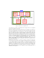
That API can be used by a software developer to implement distributed and real-time capable applications. A brief overview of eCos can be obtained from section 4. Concerning
to the hardware, FREACSIM allows the usage of different topology schemes for the in-
M0
R0
M1
R1
M2
R2
M3
R3
C
: Computation node
R
: Routing node
M
C0
C1
C2
: Shared memory
: Bidirectional link
(read/write transfers)
C3
: Unidirectional link
(trigger interrupt)
R4
M4
R5
M5
C4
M8
R8
M9
R9
R13
C12
R7
M10
R10
C7
M11
C10
M13
R14
C13
M7
C6
C9
M12
M6
C5
C8
R12
R6
R11
C11
M14
R15
C14
M15
C15
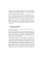
Figure 1: 4 × 4 torus-2D architecture with routing and computing nodes as well as notification of
computation cores using interrupts if new data have arrived.
terconnection of the single nodes. At the moment, the topologies star, ring, grid-2D and
torus-2D are implemented and can be used within a design. Figure 1 shows an example
and a visualization of one possible architecture (4×4 torus-2D) that can be generated and
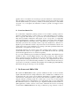
simulated with FREACSIM. Figure 2 shows an overview of the framework.
Depending on the user input, like the topology or the number of nodes to use, the tool
noc-generator creates a NoC-Design. The representation of this Design is within a self
defined XML format, what we call an XML hardware description. This XML hardware
description is the input for the tool xml-to-sim-model, which generates a complete Open
Virtual Platforms simulation model out of the XML description. We decided to introduce
this intermediate XML format for two reasons. First, the user has the ability to write self
defined hardware descriptions in the given XML format, what results in more flexibility
and independence. If there would be no XML interface, the tools noc-generator and xmlto-sim-model could be seen as one tool that is more complex. As a consequence, the
user could only use the hardware descriptions that are generated by the tool noc-generator.
Second, if a further simulation environment shall be added to the framework, only the
adaption of the tool xml-to-sim-model has to be done.
The XML hardware description contains required components, like processors or memories, as well as the interconnection of that single components that define the NoC-Design
and architecture, respectively. An example of such a NoC-Design is shown in Figure 1.
Furthermore, the tool noc-generator creates a header file that contains information about
the created hardware design, e.g. which node is interconnected directly with another node
or at which address a memory (message buffer) is accessible for a processor of a node.
This hardware information header file is the input for the the tool routing-generator. That
tool creates a software library and the required header files, that enables the (softwarebased) communication and routing between nodes in the design. The header files contain
the prototypes of our API-functions, that have to be used to communicate between nodes,
User Input
In
noc-generator
Out
XML File (Hardware Description)
Hardware Information Header File
*.xml
*.xml
*.h
*.h
In
In
xml-to-sim-model
routing-generator
Out
Out
Routing Library and Header Files
Hardware Simulation Model
*.a
*.a
*.h
*.h
*.cpp
*.cpp
*.h
*.h
*.exe
*.exe
Interface
used by
Executable Simulation Model
Application(s)
to run
Run Simulation
OVP
Results
Figure 2: Overview of the tools and components of the framework FREACSIM.
for example to send and receive data packets/messages. The library also encapsulates the
necessary libraries of eCos, to enable the real-time capability on the nodes.
Now the user is able to implement a distributed application for the NoC-Design. As already
mentioned, the applications for the single node processors have to use our API-functions
to enable the communication between nodes. We provide a set of software applications
and use cases, respectively (see section 6), that use our API.
After the implementation of the single programs of the distributed application, that single
programms have to be loaded into the processor memories of the corresponding nodes,
what is done using an interface provided by OVP. The user has the possibility to control
the simulation using parameters. One particular parameter for the simulation is the time
slice, which was elucidated in section 3. The time slice controls the simulation speed.
After the simulation has terminated, the results can be inspected and evaluated.
5.1
Architectures of Nodes
We distinguish the nodes in our designs (cf. Figure 1) into routing nodes and computation
nodes. The computation nodes shall only perform actions of applications and shall not
be busy with routing tasks. As a consequence, the routing nodes take care of the routing.
It is also possible to disable the routing nodes what results in an architecture, where no
distinction between routing and computation nodes is made and the routing as well as the
computations have to be done by the same node. The focus, however, is on architectures
that distinguish between routing and computation nodes, because node cores of (hard)
real-time capable embedded systems normally don’t want to spent time for routing tasks,
because the computing time is required for CPU-intensive computation tasks.
The base for the implementation of our software-based routing, that uses the store and forward algorithm, are single shared memories, that are connected to some computation and
routing nodes, respectively. These shared memories act as buffers, the store and forward
routing algorithm works with (see Figure 1). Which computation nodes and which routing
nodes are connected to a shared memory depends on the chosen topology and if routing
nodes are enabled or not.
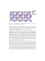
A computation node has a fixed architecture (Figure 3), a routing node has two possible
architectures.
One single computation node consists of five hardware components. These five components are required because the real-time capability is achieved by using the real-time
operating system eCos (see also section 4) that runs on every computation node in our
NoC designs. The first component is a UART controller/interface. This interface is used
for input and output calls of C-functions like printf or getc. The association of the other
four hardware components is called a core module. The core module consists of a processor, a programmable interrupt controller (PIC), a timer and some core local program
memory. This memory is loaded with the application that uses our routing library, which
contains the necessary eCos libraries. The timer generates periodically an interrupt on pin
IRQ2, which is defined as the scheduler clock of eCos, and is forwarded to the processor’s
interrupt pin (IRQ). All components are connected to a virtual OVP bus (see [Imp14b]).
That bus is the interface where a shared memory (buffer) is connected to, independent of
the chosen topology (cf. Figure 1).
A routing node can consist of the same components as a computation node (same processor, etc.) and one additional component called a signal generator. The signal generator component is a hardware component that is required for triggering interrupt pins on
computation node cores. If the notification for new data of a computation node shall be
realized using interrupts, the pins IR0 to IR6 and IR8 of the computation node interrupt
controller are used to connect a corresponding pin of the signal generator component. As
IR0 ... IR6 IR8
ARM920T
Processor
PIC
IRQ
IRQ
Timer
IR7
IRQ2
VIRTUAL BUS
CORE MODULE
Program
Memory
UART
COMPUTATION NODE
Figure 3: Architecture of a computation node.
a consequence, it is possible to send interrupts from a routing node/core to a computation
node/core for notification of new data.
Because the routing node has the same architecture as the computation node, with the exception of the signal generator component, eCos can also run on the routing node. Thus,
the real-time capability is given on a routing node, too. The other possibility of the architecture of a routing node is that the real-time capability is disabled and the routing takes
place without eCos. In that case, a routing node requires a processor, some processor local memory and the even mentioned signal generator component for triggering interrupts,
if desired. At the moment, the tool noc-generator allows to choose one of five processor types if no real-time capabilities for the routing shall be used or are required. These
five processors type are ARM920T, ARM7TDMI, ARM926EJ-S, ARM Cortex A9 and
ARM Cortex R4 [ARM15]. As a consequence of these different types of processors, it is
not only possible to build homogeneous architectures and systems, respectively, but also
heterogeneous architectures.
By using a the tool noc-generator, a wide range of settings, concerning to the architecture
of a node and the whole system, can be configured. Such settings are the overall number
of nodes, which is limited to 64 at the moment, or if routing nodes shall be used. If
computation and routing nodes shall be used, the tool allows the configuration how the
notification of a computation node, if new data for even that node are available, takes
place. Possible settings therefore are polling or interrupt . Also the type of routing core,
which is part of the routing node, can be configured as well as frequency/mips rates of
computation and routing cores.
5.2
Routing / Communication
Routing in our general NoC design means that packets are forwarded from one core to an
adjacent core on the path to the packet’s destination, what corresponds to an implementation of the store and forward algorithm [CMadHSV96].
As already mentioned, the base for the communication between nodes and for realizing
the different topology schemes are single shared memories, where specific computation
and routing nodes are connected to (cf. Figure 1). These shared memories are used to
hold the data/packets that have to be send from one computation node to another or that
are received by a computation node. For the torus-2D topology with routing nodes, four
routing nodes and cores, respectively, share such a memory (up, down, left and right).
Bounded packet sizes make memory management, flow-control, etc. much easier. Because we are geared towards routing around faulty or overloaded cores, we need to route
messages dynamically. We thus prefix each message with an eight byte message header.
Each hop in the network examines the message header to make routing decisions.
As the minimum, a single packet may be in flight between connected nodes at a time. To
gauge the performance of this extreme point, we format the shared memory that only one
packet can be placed into it at a time per attached core (single buffer). There needs to be a
single buffer per direction (send and receive). Otherwise, a message sent from computation
node to the other would overwrite a message concurrently sent in the opposite direction. A
flag in each of the two buffers indicates whether the buffer is currently in use. The sender
sets this occupied-flag once the message is completely placed into the buffer. The receiver
resets the flag once the message is copied away into local memory.
A single buffer per hop and direction has one major disadvantage: The sender needs to
wait until the receiver has copied away the message before it can send the next message.
A slow receiver can therefore stall the sender. This problem can be solved by spending
more resources (buffers) per hop and direction. To be more precise, we can format the
shared memory as linked lists of messages. The user has the choice between single buffer
or linked list communication.
The receiver of a message can either poll for the arrival of messages or can be notified
by an interrupt that a new message has arrived. Which mechanism shall be used can be
configured in the routing settings.
To implement the store and forward routing efficiently, each computation node or routing
node (when they are enabled) maintains a routing table that encodes the topology of the
network. To perform routing decisions, either the computation cores or the routing cores
need two operations: is-responsible-for-message and is-attached-core. We need the isresponsible-for-message to be able to elect a computation core (or routing core) if multiple
computation nodes (or routing nodes), attached to a given shared memory, have a link to
the destination core. The operation is-attached-core is needed, that a core knows, that the
destination core is one of its attached cores (and there is no need to forward the message
elsewhere).
If at run-time a core or network connection dies, becomes hot, or is overloaded, a neigh-
boring computation core or routing core can notice this and inform the others via a special
broadcast message. The computation cores (or routing cores) can then patch their routing
tables.
The implementation of both is-responsible-for-message and is-attached-core operations
devolve into a table look-up in a pre-computed table so that the costs are negligible.
Depending on the interconnection scheme/topology and the communication/routing settings (polling or interrupt, etc.), the required communication and routing mechanism for
data packets between nodes and cores, respectively, is generated in software as a library.
This library has a transparent interface (API) to the programmer. As a result, the NoC
software developer does not need much knowledge about the hardware.
To use our NoC design in association with our API, the programmer needs to send explicit
messages. Our API is not an end-user API such as MPI or MCAPI1 but rather designed to
build other APIs or hardware components on top of it. The API consists of send and receive
commands (in both, blocking and non-blocking variants) to send messages up-to the packet
size. The message size (MTU-size, Maximum Transmission Unit) is configurable, what
results in flexibility for the user. To make the system a little more flexible, each message
has an associated tag so that types of messages can be differentiated. Each node keeps a
set of lists (one per tag) in its private memory. Higher level layers can then build message
fragmentation/reassembly, quality of service guarantees, and high/low priority messages
on top of this message tagging scheme.
6
Applications / Use Cases
When a NoC design is created, the design is typically optimized for some software application area. This software application area has a range from applications that perform
almost no computation but mainly communicate to applications that only compute and perform little communication. We defined a set of four software applications and use cases,
respectively, that cover the extremes and single parts of these range. All applications are
written in C and are able to scale to any number of nodes supported by the framework. As
a consequence, a designer can interpolate between these use cases to get the best answers
for the application profile at hand.
6.1
Bandwidth
The bandwidth software application and use case, respectively, simply sends a MByte of
data between the nodes and then waits for a single acknowledgement message.
1 http://www.multicore-association.org/workgroup/mcapi.php
6.2
Stencil kernel
The compute-bound Stencil kernel computes the average of all the direct neighbours of
each point in a matrix and writes the result into a second matrix. Each core maintains a
partition of the matrices. At the end of each iteration, the boundary rows are exchanged
with the adjacent cores. We use a 512·512 matrix of floats. As a result, 512·4 = 2048 bytes
are transferred after each iteration in each direction. There is a computation complexity of
O(M 2 ) with a communication complexity of O(M ). Communication happens only rarely
and in periodic bursts compared to the iteration’s computation time.
6.3
QR-codes
QR-codes are 2D bar codes that encode a simple bit-string (a black square corresponds
to 1, a white square to 0) and are often printed and posted where a smartphone can take
a picture of them. Because the phone’s camera may be rotated with respect to the QRcode and the QR-code may not be centered, the QR-code detection of this application
rotates the picture to align the embedded QR-code and scans each rotated picture to find
the QR-code’s position in the picture using the corner’s encoding pattern.
Computation core 0 repeatedly rotates the image by some angle (both, clockwise and anticlockwise) and sends the results in a round-robin fashion to all other node cores in the
design. These node cores scan the received and rotated image to detect a QR-code. For the
application we use a 256 · 256 pixel RGB image (192 KByte) with an embedded 64 · 64
pixel rotated and translated QR-code. To send and receive this image the application needs
to fragment the image into packets and to reassemble them. The communication pattern is
thus a series of burst communications (3072 messages when using a 64 byte packet size)
from core 0 to the core 1, a small wait (while it rotates the image), then a burst of packets
to core 2, and so on. Bandwidth is important for this use case.
6.4
Packet Rewriter
Computation core 0 creates (artificial) Ethernet packets and sends them to the other computation cores for rewriting in a round-robin fashion. Once a packet has been rewritten,
it is returned to computation core 0 (which could conceptually forward it). Because an
Ethernet packet can be far larger than a packet of our NoC, packet fragmentation and reassembly are needed for this application as well. We solve this problem by prefixing each
packet, which is send over the NoC channels, with an extra offset field. Only after all
small packets of an IP packet have arrived, the receiver rewrites the reassembled packet
and sends it back to core 0, in fragments again.
Thus, the communication pattern in this application is a repeated sequence of a set of
1500
( packet
size ) packets sent in a small burst from computation core 0 to each of the other
computation cores followed by an almost simultaneous burst from the other computation
cores back to computation core 0. This application is mostly bandwidth-bound.
7
Results
We distinguish our results into flexibility and simulation speed of the framework FREACSIM. Some fixed settings for the measurements and some varying settings to demonstrate
the flexibility and the simulation speed are used. The focus of the flexibility measurements
is on the software-based routing, not on the possibility to simulate different hardware designs and topologies. We chose only one varying parameter for the software-based routing.
Considering more parameters and different hardware architectures would result in a design
space exploration, what is not the goal of this paper.
The fixed settings for our measurements are elucidated in the following.
The hardware architecture used for the measurements is the 4 × 4 torus-2D architecture
shown in Figure 1. This is one of the most complex Network on Chip architectures the
framework can generate. As a consequence, our experimental setup consists of 16 computing nodes and 16 routing nodes. The size of each shared memory is set to 256 kilobyte
(KB). Because the torus-2D topology is used, a single shared memory is connected to four
routing nodes for realizing the network topology. The computing nodes use the architecture, introduced in Figure 3 and section 5.1. The routing nodes use the architecture that
does not support real-time ability. The type of routing core used for the routing nodes is
set to ARM Cortex-R4. Our routing library without real-time ability runs on the routing
cores, the computation cores use the routing library with real-time ability (eCos enabled).
eCos uses the multilevel queue scheduler. The frequency of a computation core contains
the value 800 MHz and the frequency of a routing core is set to 500 MHz. For informing
the computation nodes that new messages have arrived, the routing nodes use the polling
strategy provided by the routing library and linked list messages for transfering data.
For each measurement, the applications elucidated in section 6 are running on the 4 × 4
torus-2D architecture. Each application utilizes our software base routing library and is,
as a consequence, real-time capable.
Both parts of the measurements, simulation speed and flexibility of the framework, are
illustrated in the following sections.
7.1
Simulation Speed
To show the simulation speed, and the possibility the software developer has to speed up
simulation performance, we measured the simulated times of the four use cases against the
wall clock times required for the simulation. Simulated time describes the overall time a
use case ran on the 4 × 4 NoC-architecture. Wall clock time is the overall time taken by
the simulation process on the host machine from start to end. We varied the parameter time
slice, elucidated in section 3, of the simulation from 1 microsecond over 5 microseconds
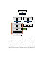
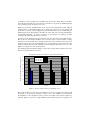
Simulated times for different time slices
1.5
Simulated time [sec]
time slice 1 us
time slice 5 us
time slice 25 us
1
0.5
0
bandwidth
stencil
QR
packet rewriter
Use case
(a) Simulated times
Wall clock times for different time slices
Wall clock time [sec]
80
time slice 1 us
time slice 5 us
time slice 25 us
60
40
20
0
bandwidth
stencil
QR
packet rewriter
Use case
(b) Wall clock times
Figure 4: Simulated times and wall clock times of the use cases for time slices 1us, 5us and 25us.
to 25 microseconds. A packet size of 64 Bytes was used for the routing. The host machine,
where the measurements were performed, was a 64 bit core i7 quad core [COR15] and the
host operating system was fedora version 21.
Figure 4(a) shows the simulated times of the four use cases bandwidth, stencil, QR and
packet rewriter for the different time slices. Figure 4(b) shows the corresponding wall
clock times. As can be seen from Figure 4(a), the simulated times vary in a small range for
different time slices, although they should be the same. The reason for that circumstance
are simulation artifacts, e.g. where a routing core spends time in a polling loop while
waiting for the quantum to finish (see section 3).
As can be seen from Figure 4(b), the larger the time slice, the shorter the wall clock time.
This is the case because the simulator does not need as many context switches for large
time slices as for short time slices. Setting the time slice very low delivers the most precise
results, because each component simulates just a view instructions in turn. One the other
hand, the wall clock time of the simulation, when setting the time slice very low, is the
highest in comparison to the other time slices.
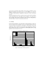
For clarifying that circumstance, Figure 5 shows the average wall clock times per simulated second of the different use cases.
Average wall clock time per simulated second [sec]
Average wall clock times per simulated second for different time slices
70
time slice 1 us
time slice 5 us
time slice 25 us
60
50
40
30
20
10
0
bandwidth
stencil
QR
packet rewriter
Use case
Figure 5: Average wall clock times per simulated second.
The results in Figure 5 show, that one simulated second never requires more than a wall
clock time of 71 seconds, independent of the use case. One simulated second includes
the simulation of 16 computation nodes as well as 16 routing nodes and the required peripherals. That corresponds to a high simulation performance and speed, respectively. As
opposed to this, we measured a wall clock time of 639 seconds per simulated second for
the gem5 environment, if just a single processor of profile ARMv7-a, e.g. Cortex A9
[ARM15], is simulated and the level of accuracy is set to low. If the level of accuracy is
set to high, the wall clock time per simulated second increases to 12771 seconds (about
3.5 hours).
By using the parameter time slice, the software developer can select between simulation
accuracy and simulation speed. That enables various possibilities to the software developer, concerning to the trade off of simulation accuracy and speed. If functionality of
real-time capable software shall be tested, the time slice can be set to a large value, because functionality of software is not affected by the time slice.
7.2
Flexibility
To demonstrate the flexibility of our routing library, and the information a software developer can obtain from those flexibility, we chose one particular parameter that varies
for every measurement. This parameter is the packet size. The packet size can be easily
configured by setting one parameter before the build of the routing library, nothing else
has to be changed. The packet size sweeps from 32 to 512 Byte and the time slice for the
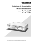
measurements was set to 1 microsecond. Figure 6 shows the simulated times for varying
packet sizes and for the different use cases.
Simulated times for different packet sizes
2.5
Simulated time [sec]
2
32 Byte
64 Byte
128 Byte
256 Byte
1.5
1
0.5
0
bandwidth
stencil
QR
Use case
Figure 6: Simulated times for different packet sizes.
packet rewriter
As expected, the measurements emphasize, that changing the packet size can have a decisive influence on the simulated time and, as a consequence, the run time of the use cases.
The results show, that the larger the packet size, the faster the application of the respective
use case. The larger the packet size, the more data can be transfered in one communication
step. This is the reason why the simulated time wanes the larger the packet size.
8
Conclusion
This paper presents the highly configurable Framework for Real-time capable Embedded
system and ArChitecture SIMulation (FREACSIM). To the best of our knowledge, there is
no other comparable fully integrated system-simulation environment, that covers the full
stack of (real-time) applications, software-based routing as well as NoC specific hardware
and architecture aspects for embedded systems.
A range of embedded processors where our configurable software-based routing can be
cross compiled or adapted and changed, respectively, is supported. As a result, we are
able to build heterogeneous as well as homogeneous Network on Chip architectures and
systems, where real-time capable and distributed software can be developed for and tested
on. As a consequence, different NoC-architectures and topologies can be evaluated with
the framework FREACSIM.
We allow the implementation of real-time capable and distributed applications by the usage of our routing library and the corresponding API. Software-based routing means, that
special nodes implement the routing functionality in software and not in hardware, what is
a good solution, if flexibility and independence shall be given. A software developer can
change and adapt all parameters provided by the routing library to his own needs. This enables flexibility to the software developer and shows the influence on his software. Thus,
the software developer can get a feeling how well his real-time capable software works on
the respective NoC-architecture or what kind of changes have to be made.
One main advantage of our framework is the simulation speed, as illustrated in section 7.
From a point of view of a software developer, simulations of large embedded systems, like
NoCs, have to be fast. Unfortunately, fast and precise simulation are in a mutual tension
relationship. For the simulation of large embedded systems, its always the question, what
kind of accuracy should be used. Complete cycle accurate simulations are not a good
solution for such large systems, because the wall clock time of the simulation is always
much greater than the simulated time. Software development does not need precise modeled hardware for testing software functionality in many cases. We think that instruction
accurate simulation is the best solution for simulating distributed software functionality
for such large embedded systems, even if the modelling of the hardware is not as precise
as on other accuracy levels.
A further benefit of the framework is the possibility to perform design space explorations
over a wide range of already available parameters. Such parameters are for example the
topology of the NoC or the frequencies of computation and routing cores. Furthermore,
our routing library supports a range of possible parameters, like the packet size (see Fig-
ure 4(a)) or the organization of the shared memories (single buffer or linked list communication). This enables flexibility and allows testing software with various configurations.
Because all virtualized hardware components exist as real components, it is possible to
build a real design out of the hardware components FREACSIM provides. Even our configurable software-based routing can be used on real hardware.
9
Future Work
Single parts of the simulation, were precise results are necessary, could be performed on a
more detailed accuracy level than FREACSIM supports at the moment. An example would
be the cycle accurate level. If only single parts are of interest, not the whole simulation has
to be cycle accurate for that purpose. Parts of interest can be particular memory accesses
or communication traffic. In order to realize the simulation of single parts, it is necessary
to switch between the accuracy levels (instruction accurate to cycle accurate and back to
instruction accurate in that example).
In future work we want to tether a second simulation environment to our framework, that
enables partial simulation on a more detailed level than the instruction accurate one. As a
consequence of that partial simulation, the simulation speed is still high, but the results are
more precise. One possible solution for that purpose would be SystemC, but there are also
other solutions and simulation environments, respectively. Our XML interface between
the tools noc-generator and xml-to-sim-model (refer to Figure 2 and section 5) is therefore
a perfect point to start from.
References
[AKPJ09]
N. Agarwal, T. Krishna, Li-Shiuan Peh, and N.K. Jha. GARNET: A detailed onchip network model inside a full-system simulator. In Performance Analysis of Systems and Software, 2009. ISPASS 2009. IEEE International Symposium on, pages
33–42, April 2009.
[ARM15]
Official ARM Website for Processors. http://www.arm.com/products/processors/index.php,
2015. Last visit on 02.02.2015.
[BBB+ 11]
Nathan Binkert, Bradford Beckmann, Gabriel Black, Steven K. Reinhardt, Ali
Saidi, Arkaprava Basu, Joel Hestness, Derek R. Hower, Tushar Krishna, Somayeh
Sardashti, Rathijit Sen, Korey Sewell, Muhammad Shoaib, Nilay Vaish, Mark D.
Hill, and David A. Wood. The Gem5 Simulator. SIGARCH Comput. Archit. News,
39(2):1–7, August 2011.
[BDH+ 06]
Nathan L. Binkert, Ronald G. Dreslinski, Lisa R. Hsu, Kevin T. Lim, Ali G. Saidi,
and Steven K. Reinhardt. The M5 simulator: Modeling networked systems. IEEE
Micro, 26:52–60, 2006.
[Bel05]
Fabrice Bellard. QEMU, a Fast and Portable Dynamic Translator. In USENIX
Annual Technical Conference, FREENIX Track, pages 41–46, 2005.
[Bos]
Boson. Boson NetSim 10 User Manual. Boson Software, LLC, 25 Century Blvd.,
Ste. 500, Nashville. Last access date: 02.10.2014.
[CMadHSV96] Robert Cypher, Friedhelm Meyer auf der Heide, Christian Scheideler, and Berthold
Vöcking. Universal Algorithms for Store-and-forward and Wormhole Routing. In
Proceedings of the Twenty-eighth Annual ACM Symposium on Theory of Computing, STOC ’96, pages 356–365, New York, NY, USA, 1996. ACM.
[COR15]
Intel Core i7-4702MQ Processor Website. http://ark.intel.com/de/products/75119/IntelLast visit on
Core-i7-4702MQ-Processor-6M-Cache-up-to-3 20-GHz, 2015.
04.02.2015.
[ECO15]
Official eCos Website. http://ecos.sourceware.org/, 2015. Last visit on 04.02.2015.
[GEM15]
Official GEMS Website. http://research.cs.wisc.edu/gems/, 2015. Last visit on
02.02.2015.
[Imp14a]
Imperas Software Limited. OVP Guide to Using Processor Models. Imperas Buildings, North Weston, Thame, Oxfordshire, OX9 2HA, UK, May 2014. Version 0.5,
[email protected].
[Imp14b]
Imperas Software Limited. OVPsim and Imperas CpuManager User Guide. Imperas Buildings, North Weston, Thame, Oxfordshire, OX9 2HA, UK, August 2014.
Version 2.3.6, [email protected].
[JBM+ 13]
Nan Jiang, D.U. Becker, G. Michelogiannakis, J. Balfour, B. Towles, D.E. Shaw,
J. Kim, and W.J. Dally. A detailed and flexible cycle-accurate Network-on-Chip
simulator. In Performance Analysis of Systems and Software (ISPASS), 2013 IEEE
International Symposium on, pages 86–96, April 2013.
[KMGGLA12] T. Karadeniz, L. Mhamdi, K. Goossens, and J.J. Garcia-Luna-Aceves. Hardware
design and implementation of a Network-on-Chip based load balancing switch fabric. In Reconfigurable Computing and FPGAs (ReConFig), 2012 International
Conference on, pages 1–7, Dec 2012.
[Mas02]
Anthony J. Massa. Embedded Software Development with eCos. Prentice Hall
Professional Technical Reference, December 2002.
[MKK+ 10]
J.E. Miller, H. Kasture, G. Kurian, C. Gruenwald, N. Beckmann, C. Celio, J. Eastep,
and A Agarwal. Graphite: A distributed parallel simulator for multicores. In High
Performance Computer Architecture (HPCA), 2010 IEEE 16th International Symposium on, pages 1–12, Jan 2010.
[MMVG03]
J. Madsen, S. Mahadevan, K. Virk, and M. Gonzalez. Network-on-chip modeling for system-level multiprocessor simulation. In Real-Time Systems Symposium,
2003. RTSS 2003. 24th IEEE, pages 265–274, Dec 2003.
[NM93]
L.M. Ni and P.K. McKinley. A survey of wormhole routing techniques in direct
networks. Computer, 26(2):62–76, Feb 1993.
[OVP15]
eCos on ARM Integrator Compact Platform. www.ovpworld.org/operatingsystems-support-ecos, 2015. Last visit on 04.02.2015.
[SoC15]
SoClib. Official SoCLib Developer Website. http://www.soclib.fr/trac/dev, 2015.
Last visit on 01.02.2015.
[SSF13]
D. Schoenwetter, V. Sieh, and D. Fey. Porting an Engine Control Application to a
Virtual Environment by using an Open Source Real Time Operating System. In DESIGN&ELEKTRONIK, editor, Embedded World Conference Proceedings, 2013,
Nuremberg, feb. 2013. WEKA FACHMEDIEN GmbH, Haar.
[Sys15]
Official SystemC Website. http://www.systemc.org, 2015. Last visit on 02.02.2015.
[WM08]
Vincent M. Weaver and Sally A. McKee. Are cycle accurate simulations a waste
of time? In Proc. 7th Workshop on Duplicating, Deconstructing, and Debunking,
June 2008.